Introduction: Why “Good” Voltage Regulators Still Fail?
Voltage regulators are considered one of the simplest circuit modules in PCB designing, and yet, voltage regulator failure is a frequently occurring design fault in PCB designs.
Modern electronic designs are voltage-sensitive, and in most cases, regulator failure is far more often related to design issues, which are often linked with thermal stress, stability problems, and PCB layout errors. Neglecting thermal stress, stability, and PCB layout in design considerations often leads to regulator failure, even if the regulator is from a reputable manufacturer.
Most good and reputable voltage regulator still fails because often designers assume that it is enough for a voltage regulator to work perfectly by just selecting output voltage and current rating of voltage regulator. However, they often forget to consider voltage regulator thermal management, stability issues, and PCB layout errors.
A voltage regulator can may fail due to several issues ;
– Overheating of regulator due to excess power dissipation
– Incorrect selection of capacitor cause regulator to oscillate
– Regulator might become unstable due to poor PCB design layout and placement.
This article will help the designers to identify the potential causes of voltage regulator failure, its repercussions, diagnoses, methods to fix and prevent them. The tutorial will also cover the practical design cases so that the designers can get insight into the real design issues and their easy fixes.
What is Voltage Regulator?
Electronic devices are designed to operate within a specific power rating, which includes both voltage and current. Current is dependent on the device load and, therefore, varies dynamically. However, the voltage supply is fixed. Therefore, the device needs a constant and uninterrupted voltage supply for its proper functioning.
Different electronic devices require different voltages for their operation, depending on their design and application. A voltage regulator is a circuit that ensures a constant output voltage regardless of the voltage variations at the input. These voltage regulators are present in almost every electronic device to maintain a constant output voltage, such as laptops, mobile chargers, computers, and many more.
Usually, the voltage regulator converts the higher input voltage into a low fixed output voltage. However, the reverse also exists, and these are called step-up regulators, which are a type of switching regulator.
Types of Voltage Regulators
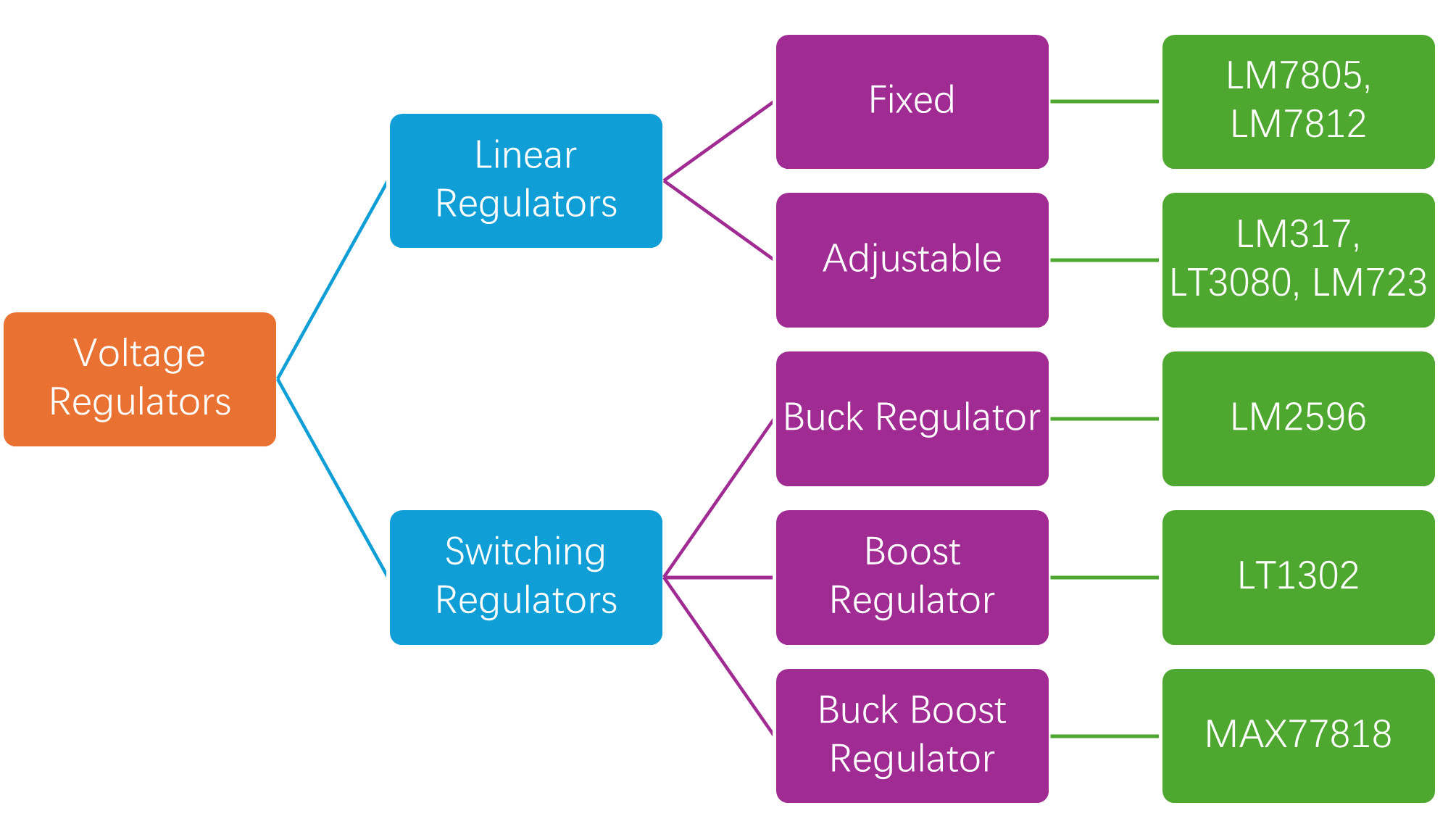
Voltage regulators are generally categorized into two major types: Linear voltage regulators and switching voltage regulators. Each type has distinct performance characteristics and failure sensitivities.
Linear Voltage Regulators
A linear voltage regulator is a type of circuit that controls the output voltage by dissipating excess energy as heat. The most famous and widely used linear voltage regulator is IC 7805, which maintains the fixed 5V output voltage regardless of the input voltage variations. They are typically used in microcontrollers, sensors, analog, and digital circuits. Other famous examples of linear voltage regulators are LM7805, LM7812, TL431 and AMS1117.
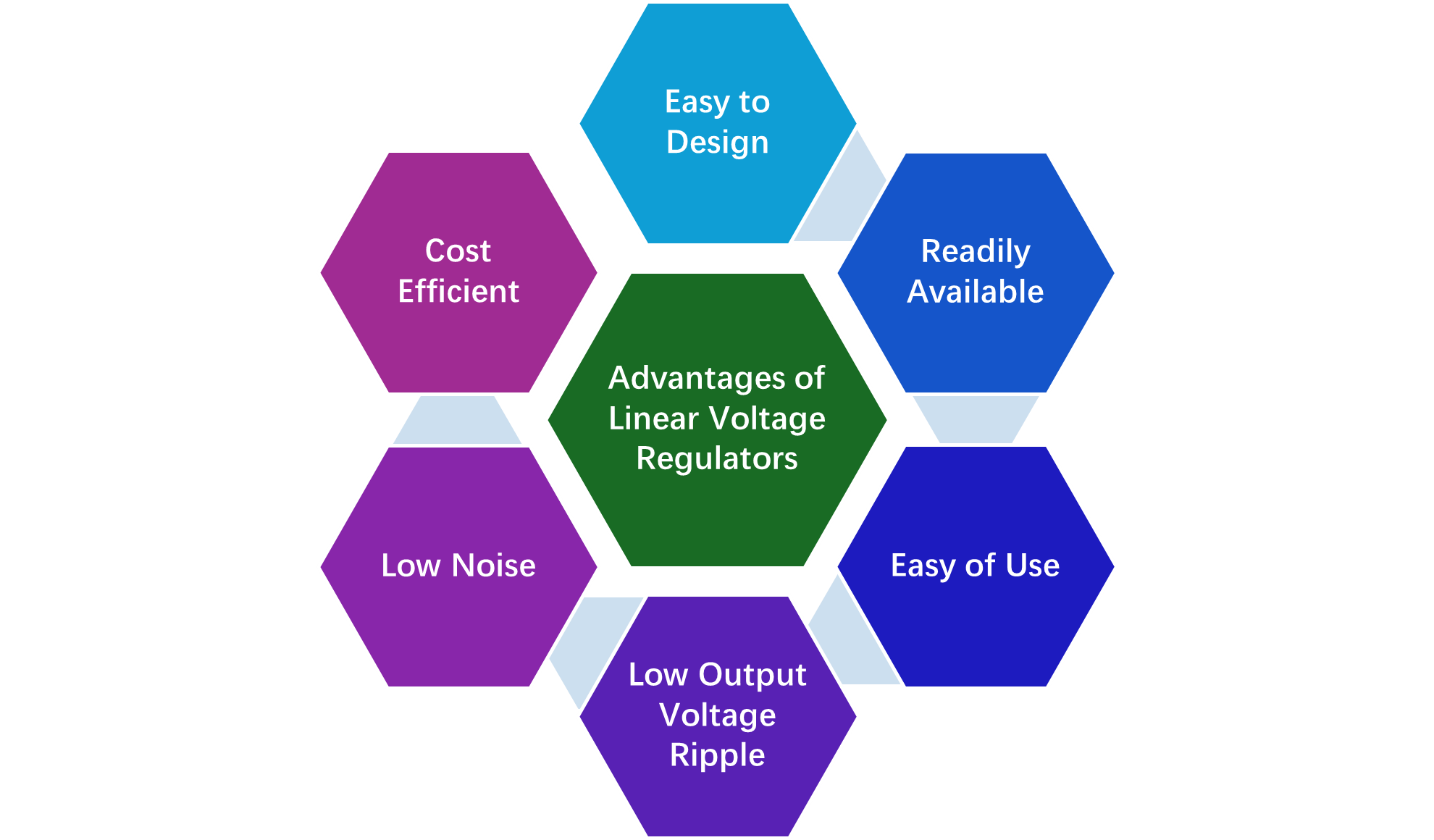
Linear voltage regulators use active devices, such as BJT or MOSFET, and are controlled through a high-gain operational amplifier. These voltage regulators adjust the constant voltage at the output by comparing the internal voltage reference to the sampled output voltage. They are easy to use and configure because most of them only require a single input and output capacitor for their proper functioning.
Low Drop Out Voltage Regulators (LDOs)
Low Dropout (LDO) is also a type of linear voltage regulator that works with a smaller voltage difference between input and output voltage, such as the NCP700 for sensors and the LM2940 for industrial applications. Low-Dropout Regulators (LDOs) are widely used in IoT and embedded system applications and come under the subclass of linear voltage regulators.
Switching Voltage Regulators
A switching regulators are DC-DC voltage converters that either step up or step down the input voltage. The switching regulator that steps down the input voltage is a buck converter, and the switching regulator that steps up the input voltage is a boost converter. Another type of switching regulator is the one that can either step up or step down the input voltage, which is a buck-boost converter.
These voltage regulators require more external components, including resistors, capacitors, and inductors. Therefore, switching regulators are more prone to experience failure compared to linear regulators because of their complex design and a higher number of external components. These are mostly used in applications that require high efficiency and compact design, such as laptops, IoT devices, computers, and the aerospace and avionics industry.
The most famous and widely used switching regulators in industries are LM2576 (Buck), LM2596, or more advanced Synchronous Rectifier controllers like TPS54331. Typical examples of these regulators are the LM2596 buck regulator, MP1584 and MP2307 compact buck regulators, LM723, HF920, and many more.
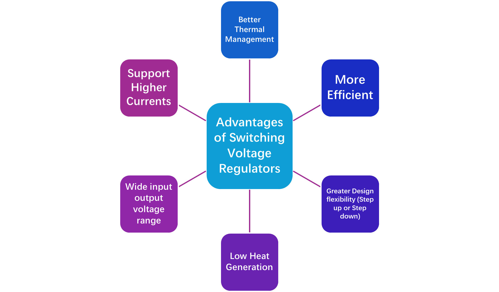
These are more complicated compared to linear voltage regulators because they require proper selection of external components, tuning control loops for stability, and careful layout design. However, switching regulators are more efficient, have better thermal performance, support higher currents, and wide input-output voltage range.
Comparison of Linear Voltage Regulators (LVR) and Switching Voltage Regulators (SVR)
Comparison Between Linear and Switching Voltage Regulators
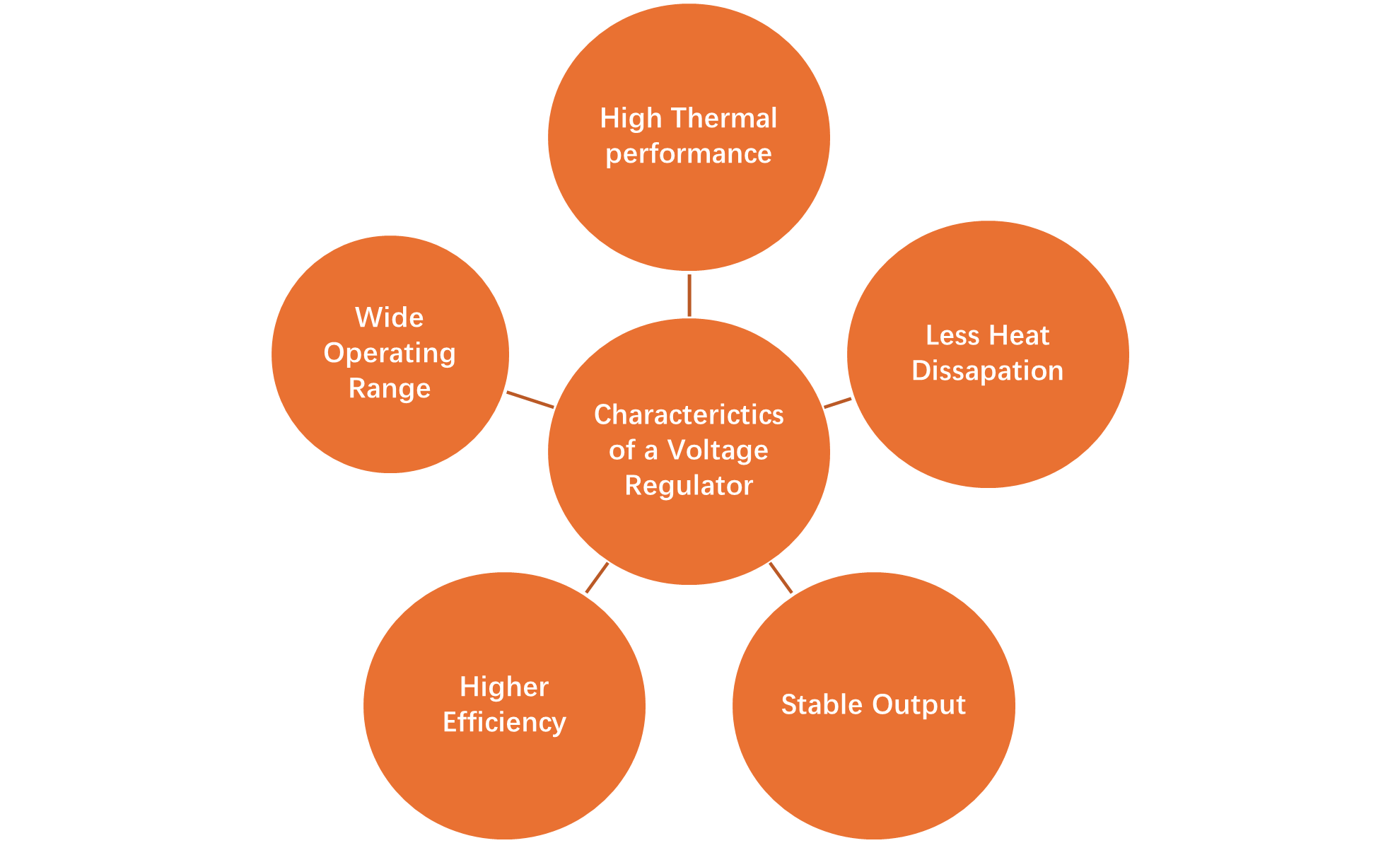
Key Characteristics of a Good Voltage Regulator
There are various applications where voltage regulators play a critical role in the performance and operation of the application. Therefore, it is important to accurately and correctly decide the best voltage regulator for your application. Before you decide the best voltage regulator for your application, consider the best characteristics of a good voltage regulator, which will be discussed in this section.
Output Voltage Accuracy
A primary characteristic of a good voltage regulator should be maintain the fixed output voltage without voltage fluctuations and within tight limits. These limits can be found using the voltage regulator manufacturer’s datasheet. For example, LM317 is an adjustable voltage regulator with an output voltage range between 1.2 V and 37 V and line regulation between 0.01 and 0.04. This voltage regulator has an output accuracy of 1%.
If the selected voltage regulator has poor output accuracy and voltage regulation, it can cause logic errors, ADV inaccuracies in embedded systems.
Thermal Performance & Heat Dissipation
This is another very important parameter that must be taken into consideration while choosing the voltage regulator for your application. Thermal performance determines the voltage regulator’s maximum junction temperature rating, thermal resistance, and the regulator’s ability to dissipate power.
Therefore, a voltage regulator that meets all the electrical characteristics but lags in thermal performance will suffer from thermal shutdown and cause voltage regulator failure. Therefore, designers must consult the datasheet and consider these parameters to ensure that their selected regulator performs as per the intended requirements.
Efficiency
The efficiency of the voltage regulator is the vital parameter because it impacts the power loss, and thermal stress of the voltage regulator. One should must consult the regulator datasheet and ensure that it has good efficiency across both light and heavy loads. It must also have low dropout voltage to ensure stable output with a smaller difference between its input and output.
A low efficiency means the regulator will generate more heat, which causes the regulator to fail. For instance, the TPS62160DSGR buck converter has an efficiency of equal to or greater than 97%.
Stable Output & Operating Conditions
A good voltage regulator must have the ability to maintain stable output across specified operating range. To ensure your voltage regulator maintains the stable output, designer must chose proper decoupling and bypass capacitors close to the pins, maintain sufficient input-output voltage difference, design a good PCB layout with short traces.
Protection & Reliability
A good voltage regulator must also have an internal protection circuit that protects the IC in case the current exceed from the limit. Therefore, the good voltage regulator includes a current limiting and short circuit protection circuit.
For more details, follow the video below on how to choose the best voltage regulator for your application.
Thermal Failures: No. 1 Regulator Killer
Among all causes of regulator failures, thermal failure is one of the most common and underestimated causes of regulator failure. The designers often consider all the electrical requirements but do not consider thermal consideration into account. This lead the design and regulator failure because heat dissipation and generation were not properly considered.
How Heat Is Generated in Voltage Regulators
The voltage regulator maintains the fixed output voltage regardless of changes in the input voltage. To maintain the fixed voltage, the voltage regulator generates heat to dissipate the excess voltage. The amount of heat depends on the regulator type and operating condition.
The designer must ensure that the regulator does not generate heat beyond the specified limit mentioned in the data sheet. This is done by carefully selecting the external components and ensuring the regulator power is within the specified limit mentioned in the datasheet. The power dissipation for linear regulators can be calculated using;
Power Dissipation in Linear Voltage Regulators
PDISS = (VIN − VOUT) × IOUT
However, in switching regulators, the heat is generated by conduction losses in switches, inductors, and switching losses at high frequencies.
Thermal Shutdown
Modern voltage regulators include a built-in thermal shutdown circuit that protects the regulator from failure in case current or junction temperature exceeds a safe limit defined by the manufacturer. This is an excellent feature, but it is better to optimize the design such that the regulator cannot cross the safe limit because multiple thermal shutdowns can cause the system to be unstable or fail.
Junction Temperature
The voltage regulator datasheet contains the critical parameter known as junction temperature. Designer must ensure that the voltage regulator should not go even slightly above the specified limit. If somehow regulator cross this limit, it will cause the regulator failure. Therefore, designers must ensure to operate the device below the specified junction temperature limit.
Common Thermal Design Mistakes
Most of the designs often fail due to the following common mistakes.
- Ignoring ambient temperature rise inside enclosures
- Using small packages (e.g., SOT-23, DFN) without thermal analysis
- Insufficient copper area for heat spreading
- No thermal vias connecting to internal ground planes
Symptoms of Thermal Failure in Real Designs
Thermal failure often comes with following common symptoms.

How to Prevent Thermal Regulator Failures
The thermal failure can be prevented by following the strategies below.

Stability Failures in Regulators
Another big cause of voltage regulator failure is becuase of stability issues. Stability issues are often confusing because a regulator may correctly work electricaly but can degrade the system performance if its control loop becomes unstable.
What is Voltage Regulator Stability?
The internal circuit of regulator consist of a feedback control loop that is responsible for maintaing the constant output voltage regardless of change in input voltage or temperature changes. However, if this internal control loop get unstable it causes the output oscillations, ringing, and excessive ripple that can cause the regulator failure.
Stability with External Components
The regulator stability is dependent on the selection of external components and PCB layout. The factors that may contribute to the instability of the regulator are output capacitor value, trace inductance, and loop area. Ignoring these parameters will cause the failure of the regulator. Therefore, the designer must ensure that the output capacitor value is exactly as specified in the datasheet by the manufacturer.
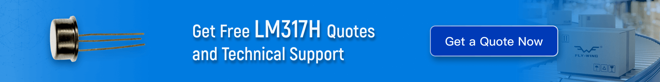
Stability Issues w.r.t PCB Layout
Poor PCB layout cause the regulator to destabilize, even if all the requirements meet the datasheet recommendations. Therefore, a good PCB layout means less chances of regulator failure. The most common layout errors are;
Symptoms of Stability Failures
The stability issues are present in the regulator; these are the most common symptoms that can indicate stability issues.
⚠️ Hidden Symptoms of Power Stability Problems
- Random resets or brownout detections
- ADC noise or inaccurate sensor readings
- Unexplained EMI compliance test failures
- Inconsistent behavior across temperature or load conditions
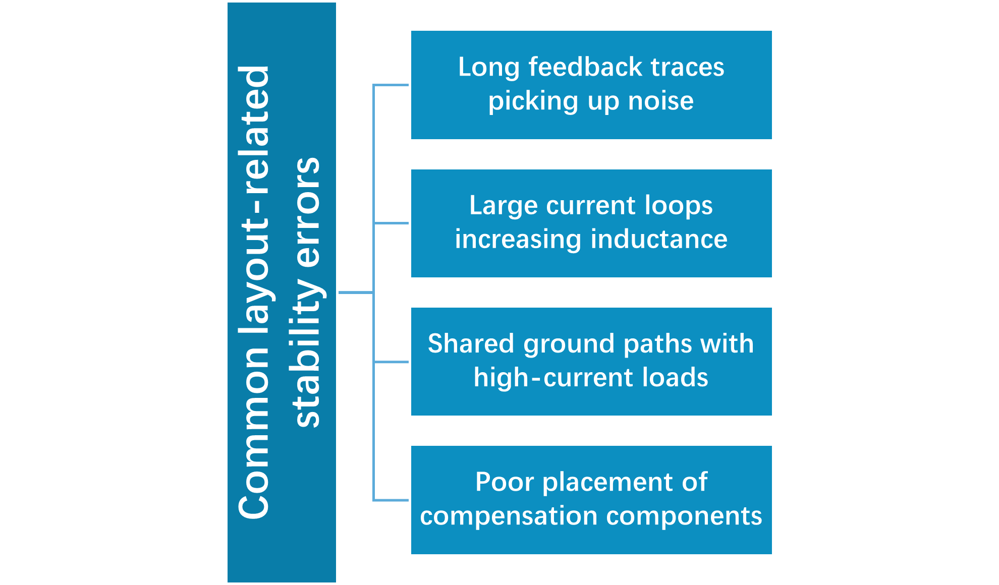
PCB Layout Errors Leading to Regulator Failures
Sometimes, the best regulator ICs can even fail due to poor layout. It may be possible that the designer has carefully selected the external components like resistors, capacitors, inductors, and their calculations, but still the regulator can fail. Because of poor PCB layout, which induces electrical, thermal, and EMI problems.
Voltage regulators are important components in the application and are able to handle both high current and high-speed signals. Therefore, poor PCB layout can introduce issues leading to regulator failure. PCB layout can introduce unwanted elements such as trace inductance, resistance, EMI coupling, and ground bounce.
Incorrect Placement of Input and Output Capacitors
The most common and obvious PCB layout mistake is to place the input/output capacitor away from the regulator pin. This is a serious offense because it cause increase voltage ripple, poor transient response, and control loop instability. Therefore, always place the input-output capacitor close to the regulator pin.
Poor Grounding and Ground Loop Issues
Another common mistake is poor grounding, which causes the regulator to fail or malfunction. The most common mistakes designers often make are;
⚠️ Common Grounding Mistakes in Power & Mixed-Signal Designs
- Shared ground paths between power and signal circuits
- High-current return paths flowing through sensitive analog ground
- Inconsistent ground reference for feedback and control signals
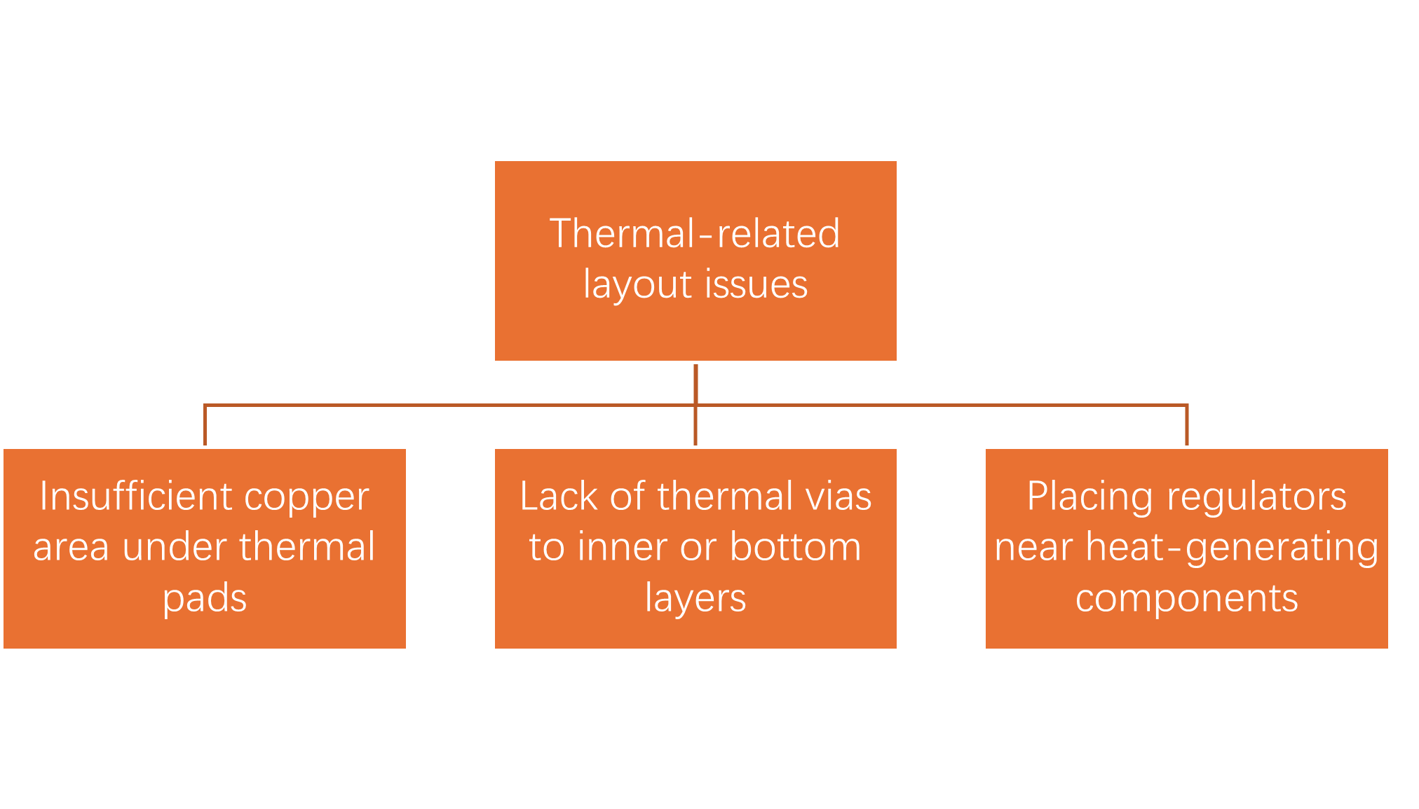
Thermal Layout Mistakes
Poor thermal layout can also lead to regulator failure. The most common thermal layout mistakes designers make are;
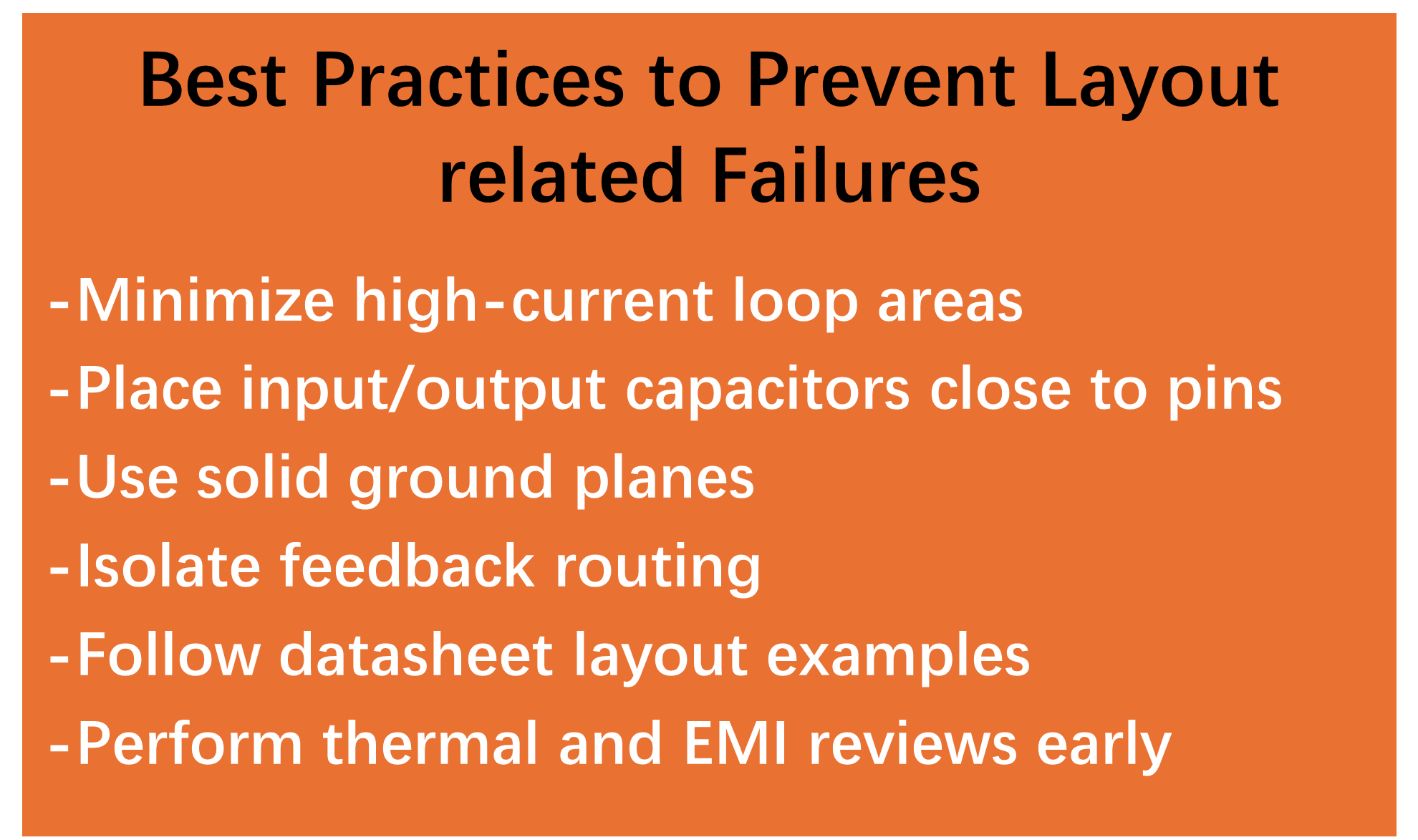
How to Prevent Layout-Related Failures
By following the best practices below, designers can prevent the layout-related failures.
Symptoms of a Bad Voltage Regulator
Voltage regultors not always immediately stops working. In some cases, regulators show early symptoms that help the design engineer to rectify the error before complete regulator failure.
Early identification of these symptoms prevent damage of components, and reduce debugging time. Below are some of the most commonly occuring symptoms in voltage regulators.
Symptoms of a Bad Voltage Regulator
Conclusion
Voltage regulators are a crucial component of modern electronic systems, and regulator failure is the most common issue that designers often encounter. Understanding voltage regulator failures, their types, and how to prevent them will help engineers to design better and optimize designs for their applications. This article has covered the most common causes of voltage regulator failures, which include thermal failures, PCB layout failures, and stability failures.
This article also covers the key characteristics of a good voltage regulator to help engineers accurately select the voltage regulator for their specific application. At the end, it covers the most common symptoms of regulator failure to help the engineers identify its cause and rectify the regulator before complete failure.
Frequently Asked Questions (FAQ)
Common signs include incorrect or unstable output voltage, increased ripple or noise, overheating or thermal shutdown, random MCU resets, and audible noise in switching regulators.
To properly test a voltage regulator, measure the output using an oscilloscope (DC and AC coupling), evaluate load transient response, monitor temperature rise, and verify operation across the full input voltage range. Compare the results with the manufacturer’s datasheet to ensure it is within the specified limits.
Yes. A failing regulator can produce overvoltage, undervoltage, or ripple, which may permanently damage MCUs, sensors, memory ICs, and analog circuits.
Common capacitor-related causes include using incorrect capacitance values, poor capacitor placement, or ignoring datasheet ESR requirements. Always follow the regulator datasheet’s recommendations for capacitor type, value, and placement to ensure stable operation.
This usually occurs due to a large VIN–VOUT difference in linear regulators, poor PCB thermal layout, insufficient copper area or missing thermal vias, or internal oscillation increasing power loss.