Introduction to TL431 Adjustable Precision Shunt Regulator
The TL431 is one of the most widely used precision shunt regulators in modern electronics, especially in power supplies, chargers, adapters, and feedback control circuits. Unlike a simple Zener diode, the TL431 provides a highly accurate 2.495 V reference, adjustable output capability, and exceptional stability across temperature and load variations. This makes it a preferred choice for engineers who need reliable, low-cost, and precise voltage regulation or error-amplifier functionality.
At its core, the TL431 behaves like an “adjustable Zener diode with an internal error amplifier.” Using a feedback network allows designers to set any reference voltage between 2.5 V and 36 V, making it extremely flexible for both low- and high-power designs. So, this versatility explains why TL431-based circuits are found in SMPS power supplies, LED drivers, battery chargers, DC-DC converters, and countless consumer electronic products.
Why TL431 is Famous?
What makes the TL431 even more valuable is its ability to work seamlessly with optocouplers, enabling safe and reliable isolated feedback in AC–DC and DC–DC converters. This is a key reason it is used by power supply manufacturers worldwide.
TL431 Pin Configuration and Package Overview
TL431 is a popular three-terminal, adjustable precision shunt voltage regulator. Understanding the pinout and its function is essential before one can use it in a design application because incorrect pin orientation is one of the most common causes of design errors and component failure. TL431 is a simple 3-pin device; each pin plays a key role in how the regulator senses, compares, and controls voltage.
Pinout Description (REF, ANODE, CATHODE)
The TO-92 TL431 uses a 3-pin layout with the following functional assignments (check your specific manufacturer datasheet, as pin order may vary). In typical designs:
- When REF > 2.495 V, TL431 conducts between CATHODE → ANODE.
- When REF < 2.495 V, TL431 turns off.
TL431 Pin Functions – Detailed Explanation
| Pin Number | Pin Name | Function | Description |
|---|---|---|---|
| 1 | REF | Voltage-setting input | Compares the divided voltage with the internal 2.495 V reference to control conduction. |
| 2 | ANODE | Negative terminal | Works like the anode of a Zener diode; typically connected to ground or the lower potential. |
| 3 | CATHODE | Output terminal | Acts as the regulated output; TL431 sinks current here based on feedback from the REF pin. |

Typical Package Types
TL431 is available in several compact package options, suitable for everything from through-hole prototypes to high-density surface-mount PCBs. Most common packages are;
TL431 – Common Package Variants
| Package Type | Mounting Type | Key Features | Notes |
|---|---|---|---|
| TO-92 | Through-hole | Used in power supplies, chargers, SMPS | Most common; check pin order (REF–ANODE–CATHODE) |
| SOT-23 | SMD | Very compact; ideal for consumer electronics | Pin numbering differs from TO-92 |
| SOT-89 | SMD | Better thermal performance | Suitable for medium-power designs |
| SOT-223 | SMD | Low-profile with good heat dissipation | Less common but thermally strong |
| SOIC-8 / DIP-8 | SMD / Through-hole | Used in enhanced-accuracy versions | Multiple configurations available |
Note: All packages have the same functional pins, but the physical pin numbering changes. Always verify the manufacturer’s datasheet when designing a PCB.

TL431 TO-92 Package Symbol & Footprint
TL431 comes in various packages as described above. So, to simplify PCB design and reduce the chance of footprint or orientation errors, the verified schematic symbol, PCB footprint, and 3D model of TO-92 for the TL431 are provided for you to download. Please click the link below to download the .zip files of TL431 symbols, footprints, and 3D model of the TO-92 package for Altium Designer.
TL431 Altium Designer Software Symbol and Footprint


TL431 3D Step Model

TL431 Block Diagram & How it Works?
The TL431 is widely used as a precision shunt regulator, but internally it operates much like a programmable Zener diode combined with an op-amp. Understanding its block diagram and working principle is essential for designing stable power supplies, reference circuits, chargers, and feedback loops.
The TL431 shunt regulator consists of three well-defined functional blocks, i.e., precision 2.495V bandgap reference, internal error amplifier, and high-gain cathode transistor at the output stage. The block diagram of TL431 is shown below.

Precision 2.495V Bandgap Reference
First, a reference voltage of 2.495V is generated, which is used to compare the REF Pin voltages. This ensures high accuracy even under varying load and temperature conditions.
Internal Error Amplifier
The error amplifier compares the REF pin voltage to the internal 2.495V reference. It functions similarly to an operational amplifier with high open-loop gain because its output drives the transistor that regulates the current of TL431.
If V(REF) < 2.495V → error amplifier output goes low → transistor reduces cathode current (device OFF).
If V(REF) > 2.495V → amplifier output goes high → transistor increases cathode current (device ON).
This feedback loop efficiently regulates the output voltage.
High-Gain Cathode Transistor (Output Stage)
This transistor sinks current from the cathode to the anode. Its conduction level determines how much current is shunted to regulate the output voltage. The higher the gain, the faster TL431 corrects voltage deviations.
How TL431 Works?
In the first step, the resistor voltage divider network is connected from the output voltage to the REF pin. So, the resistor divider network determines the desired output voltage.
In the second step, the error amplifier continuously monitors and compares the VREF voltage with 2.495V.
At the output stage, a high-gain output transistor adjusts the cathode current. Whenever the output voltage drops, REF voltage also drops, thus TL431 reduces the cathode current. Therefore, Output rises. Similarly, when the output voltage rises, the REF voltage also increases, and the TL431 draws more cathode current. Therefore, output drops.
TL431 Reference Voltage Formula & Calculations
Designing circuits with the TL431 requires an understanding of how to calculate the reference voltage and set the output voltage using external resistors. Because the output voltage is set using a simple resistor divider:
- R2 = bottom resistor (from REF to GND/anode)
- R1 = top resistor (from output to REF)
TL431 Output Voltage Formula
Choosing R1 and R2 (Design Guidelines)
To ensure the stable operation of the TL431 shunt regulator.
- Keep REF pin bias current ≥ 1 µA (ideal = 2–5 µA).
- Use resistor values in the range 2.2 kΩ to 100 kΩ.
- Avoid extremely low values (<1 kΩ), as they waste power.
- Avoid extremely high values (>200 kΩ), as they introduce noise.
- Maintain a stable RC filter if the output ripple is high (SMPS).
Example 1: Designing 5 V Output
TL431 Output Voltage Calculation Example
Given:
VOUT = 5V
VREF = 2.495V
R2 = 10 kΩ
R1 / 10k = (5 / 2.495) − 1 = 1.003
R1 ≈ 10.03 kΩ
Closest Standard Values:
• 10 kΩ → VOUT ≈ 4.99V
• 10.2 kΩ → VOUT ≈ 5.06V
TL431 Circuit Design Guide
The TL431 is widely used in SMPS feedback loops, DC voltage references, battery chargers, and precision analog circuits, but achieving reliable results requires careful attention to resistor selection, cathode current, compensation networks, and PCB layout. the following step-by-step guide explains the exact design workflow, practical considerations, stability requirements, and calculations you must verify before implementing the device on a PCB.
Step 1 — Define requirements
The first and foremost important step is to define the desired output voltage from TL431 and determine the maximum and minimum load currents.
Step 2 — Select TL431 variant & package
Step two is about determining the TL431 regulator variant and package because there are different packages, such as TO-92, SOT-23, and SOT-89, of TL431 available. One can decide the package based on their assembly and thermal needs. So, verify datasheet max cathode voltage (~36 V) and max cathode current (typ. 100 mA).
Step 3 — Calculate resistor divider
The output voltage is already fixed in the first step. Now, using the output voltage, determine the values of the resistor divider network, i.e., R1 and R2. Pick R2 and solve for R1. A common choice for R2 as a starting point can be 10kΩ.
Step 4 — Ensure proper cathode current margin
Now, determine the required minimum cathode current to maintain the regulation. So, always consult the datasheet of TL431 for knee current, which is typically 100uA. Also, add the current limiter resistor to keep the cathode current within the safe range, i.e., 1mA to 100mA.
Technical Specifications of TL431
TL431 mostly comes in TO-92 and SOT-23 packages and is manufactured by different companies, such as Texas Instruments (TI) and STMicroelectronics. When using a TL431 precision shunt regulator in your circuit design, it is important to understand its technical specifications to ensure that the device works as per the expectations. To know the exact technical specifications, always consult the datasheet because different variants can have slightly different specifications.
Technical Specifications of TL431
| Parameter | Typical Value / Range | Description |
|---|---|---|
| Reference Voltage (Vref) | 2.495 V (Typical) | Internal precision reference voltage used for regulation. |
| Operating Cathode Voltage Range | 2.5 V to 36 V | Output voltage range the device can regulate. |
| Adjustable Output Voltage Range | 2.5 V to 36 V | Programmable reference using external resistor divider. |
| Reference Voltage Tolerance | ±0.5%, ±1%, ±2% | Determines accuracy of output voltage regulation. |
| Cathode Current (IK) | 1 mA to 100 mA | Minimum and maximum operating current through cathode. |
| Minimum Operating Current (Imin) | 1 mA | Current required to maintain regulation. |
| Dynamic Output Impedance | 0.2 Ω (Typical) | Indicates stability during load changes. |
| Temperature Range | –40°C to +125°C | Suitable for industrial and consumer applications. |
| Thermal Resistance (θJA) | ~150°C/W | Heat dissipation capability of the package. |
| Package Options | TO-92, SOT-23, SOT-89, SOIC-8, DIP-8 | Common available packages. |
| Stability Requirement | External capacitor needed | Ensures loop stability under dynamic loads. |
| Output Impedance | < 0.22 Ω | Helps maintain tight voltage regulation. |
| Turn-On Response Time | < 1 µs | Fast transient response for control loops. |
TL431 Precision Shunt Regulator Application Circuits
The TL431 is widely used across power supplies, battery chargers, industrial controllers, and feedback loops because of its high accuracy, programmable reference, and robust transient response. Its ability to operate like an adjustable Zener diode makes it a versatile choice for voltage regulation, current limiting, and reference stabilization in both low-power and high-performance designs. In this section, I have simulated two real-world applications using the TL431, namely “Battery charging circuit using TL431” and “Constant linear voltage regulator”.
Battery Charging Circuit Using TL431
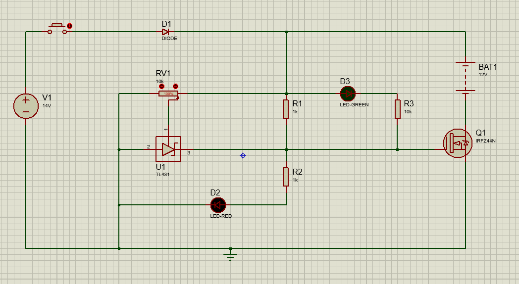
The TL431 adjustable shunt regulator is widely used in precision voltage regulation and battery management applications because of its high accuracy and flexible adjustable output. In this battery charging circuit application, I have use TL431 as a battery charging controller.
The circuit uses a 14V DC supply, and a diode (D1) provides reverse polarity protection to safeguard the system. A variable resistor (RV1) is used to set the reference voltage at which the TL431 begins regulating. When the battery voltage is below the set threshold, the TL431 remains off, allowing charging to continue, while the red LED indicates the battery is charging as shown in figure below.
As the battery reaches the target voltage, the TL431 conducts, turning on a MOSFET (IRFZ44N), which effectively limits the charging current. Simultaneously, the green LED lights up to indicate the battery is fully charged, and the red LED turns off as shown in the circuit diagram.

TL431 as a Constant Linear Voltage Regulator
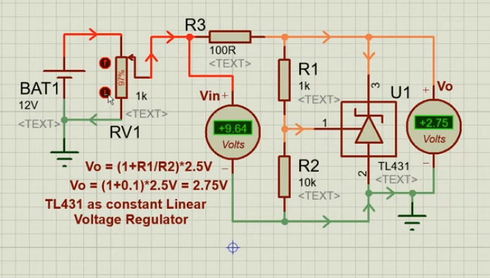
In this application, I have used TL431 as a constant linear voltage regulator. The circuit is input through a 12V battery; the input voltage is slightly reduced using a series resistor (R3) to limit the shunt current. So, the output voltage is determined by a simple resistor divider network connected to the TL431’s reference pin.
The TL431 regulates output voltage by comparing the reference pin voltage (REF) with its internal 2.495V reference.
So, the adjustable output voltage is given by:
TL431 Output Voltage Calculation
Formula:
Calculation for 2.75 V Output:
2.75 = (1 + R2 / R1) × 2.5
1 + R2 / R1 = 2.75 / 2.5
R2 / R1 = 1.1 – 1 = 0.1
R2 = 0.1 × R1
Using standard resistor values:
If R1 = 10 kΩ → R2 ≈ 1 kΩ → Output ≈ 2.75 V
The TL431 constantly adjusts its conduction to maintain the reference voltage at 2.495V, ensuring the output remains stable even if the input fluctuates, as shown in the circuit diagram below. This configuration is ideal for applications that require a low-current, stable voltage, such as precision sensor references, comparator thresholds, or low-power analog circuits.

TL431 VS Zener Diode
Unlike a standard Zener diode, which typically has a wide tolerance of ±5% or more, the TL431 provides a high-precision internal reference of 2.495V, with available grades offering ±0.5% accuracy. This makes it ideal for circuits where tight voltage regulation is critical, such as precision voltage references, feedback loops in switch-mode power supplies, or battery monitoring systems. The TL431 is also adjustable via external resistors, allowing designers to program the output voltage across a wide range (2.5V to 36V) without changing the component, whereas a Zener diode has a fixed breakdown voltage that requires replacing the diode for different voltages.
TL431 Voltage Regulator VS Alternatives
When designing precision voltage regulation circuits, the TL431 adjustable shunt regulator often stands out for its flexibility and accuracy. However, depending on the application requirements, such as output voltage range, accuracy, current capacity, and temperature stability, engineers may consider several alternatives. Common options include traditional Zener diodes like the 1N4733A, precision voltage reference ICs such as LM4040, and high-accuracy references like REF102.
Each option has unique strengths and limitations, making it essential to compare their performance characteristics to select the best fit for your circuit. So, the table below summarizes TL431 and its popular alternatives, highlighting key parameters that affect design decisions.
TL431 vs Other Voltage Reference & Regulator ICs
| Feature / Parameter | TL431 | Zener Diode (1N4733A) | LM4040 (Voltage Reference IC) | REF102 (High-Precision Reference) | LDO Regulator |
|---|---|---|---|---|---|
| Type | Adjustable shunt regulator | Fixed shunt voltage | Precision voltage reference | Precision voltage reference | Linear voltage regulator |
| Output Voltage | Adjustable (2.5V–36V) | Fixed 5.1V | Fixed 2.5V–10V | Fixed 5.0V | Fixed or adjustable |
| Accuracy | High (±0.5% typical) | Low (±5–10%) | High (±0.1–0.5%) | Very high (±0.02%) | Moderate to high |
| Temperature Stability | Good | Poor | Excellent | Excellent | Moderate |
| Current Handling | Moderate (1–100 mA typical) | Low (up to 50 mA) | Very low (µA range) | Low (up to 10 mA) | High (up to A range) |
| Adjustability | Yes (via external resistors) | No | No | No | Sometimes (depends on type) |
| Complexity / Components | Low (few external parts) | Very low | Low | Low | Higher (requires capacitors) |
| Best Use Cases | Precision power supplies, battery chargers, voltage monitoring | Simple voltage clamping or reference | High-precision voltage reference circuits | Ultra-precise references for measurement systems | Regulated power supply with higher current load |
Conclusion
To conclude, the TL431 precision adjustable shunt regulator is among the widely use regulators in modern electronics. It’s combination of high accuracy, low temperature drift, and adjustable output voltage makes it ideal for applications ranging from battery chargers and power supplies to precision voltage monitoring and feedback control in switching converters.
When compared to alternatives like Zener diodes, LM4040, REF102, or LDO regulators, TL431 stands out for its unique balance of cost, flexibility, and performance. By understanding its operating principles, selecting the right resistor network, and applying compensation techniques, designers to build highly reliable, low-noise, and efficient circuits.
Whether in industrial, automotive, or consumer electronics, this regulator provides a practical solution for precise voltage regulation, bridging the gap between simple reference devices and complex regulator ICs.
Frequently Asked Questions (FAQ)
The TL431 typically operates from 0°C to 70°C in commercial grade and up to 125°C in industrial grade. Its low temperature coefficient (≈50 ppm/°C) ensures stable voltage references in harsh environments, so, making it suitable for industrial sensors, motor controllers, and high-precision instrumentation.
Yes, Standard TL431 requires a minimum cathode-to-anode voltage of ~2.5V. For circuits below 3V, you must ensure proper biasing or consider low-voltage variants like TLV431 to maintain regulation performance.
Adding a small ceramic capacitor (10nF–100nF) between the reference pin and ground significantly reduces high-frequency noise. Because Using low-value series resistors and proper PCB layout techniques ensures stable operation in audio, sensor, and measurement applications.
Adding a small capacitor (10–100 nF) between the REF pin and ground, along with proper compensation resistors, improves phase margin and transient response.
Use small RC networks at the REF pin, maintain adequate cathode current above minimum threshold, and select proper series-pass transistor compensation to avoid instability caused by reactive loads.
