Converting AC power into usable DC is a fundamental requirement in electronics design.
Because most electronic systems operate on DC, engineers rely on efficient rectification methods.
A full bridge rectifier performs this conversion by rectifying both halves of the AC waveform.
It delivers higher average DC output, lower ripple, and better power utilization than half-wave designs. For this reason, it serves as the standard front-end stage in modern power supplies and switched-mode converters.
Despite its widespread use, engineers often underestimate the impact of diode selection, voltage drops, ripple behavior, and filtering on real-world performance. Poor design choices can lead to excessive heat, unstable output voltage, and reduced efficiency.
This article explains how a full wave bridge rectifier works, its circuit diagram and output waveform, key design formulas, efficiency limits, and common applications, along with practical guidance for selecting the right diodes or bridge rectifier modules.
What Is a Full Bridge Rectifier?
A full bridge rectifier is an electronic circuit that converts alternating current into direct current using four diodes in a bridge configuration.

The diode bridge changes the AC so the current always flows through the load in the same direction, even when the input voltage flips.
This produces a full-wave, pulsating DC output with higher average DC and lower ripple than a half-wave rectifier.
The circuit converts both positive and negative AC halves into a single-direction, pulsating DC output. A full wave bridge rectifier delivers higher efficiency than a half-wave rectifier by using the entire AC cycle.
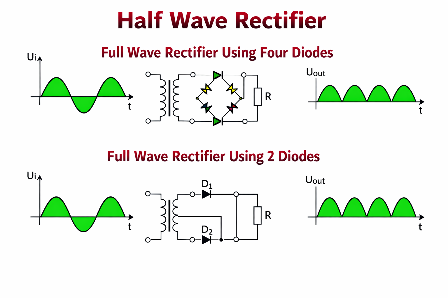
Engineers achieve full-wave rectification using either a four-diode bridge or a center-tapped transformer with two diodes.

Center-tapped transformers are typically larger, more expensive, and less flexible. A full bridge rectifier eliminates the center tap, works with standard AC sources, and dominates modern power supply designs.
Full Bridge Rectifier Circuit Diagram
The diagram shows a typical full wave bridge rectifier circuit. Four diodes, labeled D1 through D4, are connected in a closed-loop bridge arrangement.

The AC input is applied across two opposite corners of the bridge while the DC output is taken from remaining two corners.
One junction of the diodes provides the positive output (+Vout), and the opposite junction provides the negative output (–Vout).
As the AC input alternates, only two diodes conduct during each half-cycle, while the other two remain reverse-biased.
In practical designs, the four diodes may be used as discrete components or integrated into a single bridge rectifier module.
These modules typically include clearly marked AC (~) input terminals along with + and – DC outputs. This making them easier to wire and especially convenient for power supply and charger applications.
How a Full Bridge Rectifier Works
The full bridge rectifier becomes much easier to understand when you look at how current flows during each half-cycle of the AC input.

Positive half-cycle Operation
When the AC input goes positive, one input terminal becomes positive relative to the other.
In this condition, diodes D1 and D2 are forward-biased and start conducting, while D3 and D4 remain reverse-biased.
Current flows from the AC source, through D1, passes through the load from the positive output to the negative output, and then returns through D2 to the AC source.
The load therefore sees current flowing in a fixed direction.
Negative half-cycle Operation
When the AC input reverses polarity, the roles of the diodes change. Diodes D3 and D4 now become forward-biased, while D1 and D2 switch off.
Current flows from the AC source through D3, passes through the load in the same direction as before, and returns through D4.
Even though the input polarity has flipped, the bridge ensures the load current direction remains unchanged.
The bridge effectively flips the negative half-cycle so the output remains a unidirectional, pulsating DC.
One practical detail to keep in mind is diode voltage drop. Two series diodes conduct per half-cycle, reducing the output voltage by their combined forward drop.
Standard silicon diodes typically cause a 1.2–1.4 V loss, which matters in low-voltage power supply designs.
Output Waveform of Full Bridge Rectifier
Before filtering, a full wave bridge rectifier produces a pulsating DC waveform.
The rectifier converts both AC half-cycles into positive half-sine pulses by flipping the negative waveform upward.
As a result, with a 50 Hz AC input, the rectifier produces a 100 Hz pulsating DC output.
The graph shows the AC input waveform and the unfiltered DC output from the bridge rectifier.

As shown, the output never goes negative. It “oscillates” between zero and a positive peak value.
Ripple describes how much the output voltage rises and falls during each rectified cycle. A full-wave rectifier produces less ripple because shorter gaps exist between output pulses.
A full-wave rectifier has a ripple factor of ~0.482, much lower than ~1.21 for half-wave designs. To smooth this ripple, a filter capacitor is usually placed across the output.
The capacitor charges up near the peak of each pulse and then discharges slowly into the load during the intervals between peaks, thereby filling in the dips.
A sufficiently large capacitor holds the output near the peak between pulses, significantly reducing ripple.
Full Bridge Rectifier Formula
If you want to evaluate or design a full wave bridge rectifier, a few key formulas help describe its electrical performance.
Average DC Output Voltage
For a sinusoidal AC input and ideal diodes, the average DC output voltage of a full bridge rectifier (without filtering) is:
\[V_DC = (2 × V_max) / π\]
\[V_DC ≈ 0.637 × V_max\]
\[V_DC ≈ 0.637 × (V_max − 2V_D)\]
Here, Vmax is the peak value of the AC input voltage.
Because a full bridge rectifier uses both the positive and negative half-cycles of the AC waveform, the average DC output is twice that of a half-wave rectifier, which has an average output of approximately Vmax/π ≈ 0.318Vmax.
In real circuits, the actual DC output voltage will be slightly lower due to diode forward voltage drops.
Because two diodes conduct in series each half-cycle, standard silicon diodes reduce the peak output by about 1.2–1.4 V.
This reduction becomes especially important in low-voltage power supply designs.
Ripple Factor
The ripple factor measures how much AC variation remains in the rectifier output relative to its DC level. For an unfiltered full wave bridge rectifier, the ripple factor is:
\[γ = 0.482\]
This is significantly lower than the ripple factor of a half-wave rectifier, which is approximately 1.21. The lower ripple factor means the output voltage of a full wave bridge rectifier is smoother even before filtering.
In practical power supplies, adding a smoothing capacitor after the rectifier dramatically reduces ripple further, often by an order of magnitude or more depending on the load current and capacitor value.
Rectification Efficiency
Rectification efficiency (η\etaη) describes how effectively the rectifier converts AC power into usable DC power:
\[η = (P_DC / P_AC) × 100%\]
For an ideal full bridge rectifier, the maximum theoretical efficiency is approximately 81.2%. This is about double the efficiency of an ideal half-wave rectifier, which is around 40.6%.
In real-world circuits, efficiency is slightly lower due to diode conduction losses, transformer losses, and heat dissipation.
Even so, full bridge rectifiers remain far more efficient than half-wave designs and are the standard choice in modern power supplies.
Full Bridge Rectifier vs Half Wave Rectifier
| Feature | Full Bridge Rectifier (Full-Wave) | Half-Wave Rectifier |
| Diodes Required | 4 diodes (bridge configuration) | 1 diode |
| Transformer | Not needed (no center tap required) | Not needed (but only uses half of AC cycle) |
| Utilization of AC | Full-wave – uses entire AC cycle (both halves) | Half-wave – uses only one half of AC cycle |
| Average DC Output | ~0.637 × V_max (higher DC output) | ~0.318 × V_max (lower DC output) |
| Output Frequency | Twice the AC frequency (pulses every half-cycle) | Same as AC frequency (one pulse per cycle) |
| Ripple (unfiltered) | Lower ripple (smoother output) | Higher ripple (more pulsation) |
| Ripple Factor | ~0.482 (lower, smoother) | ~1.21 (higher, choppier) |
| Efficiency (ideal) | ~81.2% (high efficiency) | ~40.6% (low efficiency) |
In short, the full wave bridge rectifier is superior in performance: it provides a higher DC level and smoother output for the same input, and it makes much better use of the transformer or AC source power.
The trade-off is that it requires four diodes instead of one, meaning a slightly more complex circuit and two diode drops in the current path.
Designers use half-wave rectifiers only in low-current or non-critical applications because they produce high ripple and waste half the available DC voltage.
Full-wave bridge rectifiers are the standard choice for most power supplies since they deliver a far better DC supply quality.
Applications of Full Bridge Rectifier
We use full wave bridge rectifiers anywhere AC power needs to be converted into DC. This makes them one of the most widely deployed power components in electronics.

AC/DC Power Supplies and Adapters
Almost all consumer electronics that plug into a wall outlet rely on a bridge rectifier at the input stage.
Devices such as mobile phone chargers, laptop adapters, televisions, radios, and computer power supplies first convert mains AC (typically 120 V or 230 V) into DC using a full bridge rectifier before further filtering and regulation.
This initial rectification stage is critical for providing a stable DC foundation for the rest of the power supply.
Battery Chargers
We use full bridge rectifiers in battery charging circuits to convert AC into DC. Bench power chargers, inverter chargers, and many industrial charging systems use a bridge rectifier at the front end.
Because a full-wave rectifier delivers current during both half-cycles of the AC input, it provides a smoother and more consistent charging current than a half-wave design, which helps improve charging efficiency and battery lifespan.
SMPS Front-End
In switched-mode power supplies, the bridge rectifier is typically the first block after the AC input, creating the DC bus that the converter stage switches and regulates.
This architecture powers devices from compact phone chargers to high-power PC and server supplies, making the bridge rectifier central to modern SMPS design.
Embedded AC–DC Converters
Many embedded and industrial systems operate from an AC source but require DC internally.
Designers place a bridge rectifier and filter capacitor directly on the PCB to generate a DC rail for regulators and control electronics.
Examples include microcontroller-based control units, industrial sensors, and automation equipment. AC-fed motor drives and controllers also use bridge rectifiers to create a DC bus for driving DC or AC motors.
Household and Industrial Electronics
Bridge rectifiers convert AC to DC in appliances, LED lighting, industrial controls, HVAC systems, and power distribution equipment.
Their reliability, efficiency, and flexibility make full bridge rectifiers a core component in power conversion.
Common Diodes Used in Bridge Rectifiers
The choice of diodes in a full wave bridge rectifier depends mainly on three factors: voltage rating, current handling, and switching speed.
Different applications place different demands on the rectifier, which is why several diode types are commonly used.
1N4007 and the 1N400x Series
The 1N4007 is one of the most widely used general-purpose rectifier diodes. It is rated for about 1 A forward current and up to 1000 V reverse voltage, making it suitable for many low- to moderate-power AC-DC conversion tasks.
The broader 1N400x family (1N4001 through 1N4007) differs mainly in voltage rating, with the 1N4007 offering the highest margin for mains-related designs.
These diodes are inexpensive, reliable, and commonly used in wall adapters, small power supplies, and basic charger circuits.
Bridge Rectifier Modules
For higher power or cleaner layouts, many designs use integrated bridge rectifier modules instead of four individual diodes.
These modules contain a complete diode bridge in a single package, usually with four terminals: two marked “~” for AC input and “+” and “–” for DC output.
The KBPC series is a popular choice for mains-powered applications. These modules are available in a wide range of current ratings, from a few amps up to 50 A or more, with voltage ratings commonly reaching 600 V to 1000 V and beyond.
Larger KBPC variants mount to a heatsink. This makes them ideal for power supplies, motor drives, and industrial equipment.
Their clear terminal markings and mechanical robustness also simplify assembly and reduce wiring errors.
Fast and Ultrafast Recovery Diodes
In higher-frequency applications, such as certain power converters or the secondary side of switched-mode power supplies, standard rectifier diodes like the 1N4007 may be too slow.
These diodes take microseconds to turn off, which can lead to increased switching losses and heat.
In such cases, engineers prefer fast recovery or ultrafast diodes. Devices like the UF4007 offer similar voltage ratings to the 1N4007 but switch off much faster.
This makes them better suited for high-frequency rectification and improved efficiency in modern power designs.
Schottky Diodes
When efficiency and low voltage drop are critical, Schottky diodes are often used.
A typical Schottky diode has a forward voltage drop of around 0.3–0.4 V, compared to about 0.7 V for standard silicon diodes.
This lower drop reduces power loss and heat generation, which is especially important in low-voltage, high-current supplies such as 5 V or 12 V DC rails.
The limitation of Schottky diodes is their lower reverse voltage rating. Most silicon Schottky diodes handle less than 200 V, which prevents their use in direct mains rectification.
Designers use standard silicon diodes or silicon carbide (SiC) Schottky diodes for high-voltage applications.
SiC devices can handle voltages of 600 V and above, offering fast switching and improved efficiency at higher voltages.
Final Thoughts
The full bridge rectifier remains the preferred solution for AC-to-DC conversion because it efficiently uses both halves of the AC waveform, delivers higher average DC output, and produces lower ripple compared to half-wave designs.
Its ability to operate without a center-tapped transformer also makes it simpler, more compact, and more cost-effective for most applications.
The rectifier itself is only part of the story. Diode forward voltage, peak inverse voltage ratings, ripple frequency, filtering capacitors, and load conditions all directly influence real-world performance.
Choosing the right diode type or bridge rectifier module and pairing it with proper filtering is what turns a basic rectifier into a dependable power stage.
If you are building a simple charger, designing an SMPS front end, or working on an embedded AC–DC converter, a solid understanding of full bridge rectifiers leads to better design decisions and more reliable systems.
If you are sourcing components for your design, Flywing Tech offers a wide range of rectifier diodes, bridge rectifier modules, and supporting components to match both low-power and high-current applications.
FAQs
Why are 4 diodes used in a bridge rectifier?
Four diodes enable full-wave rectification without a center-tapped transformer.
Two diodes conduct during the positive half-cycle, while the other two conduct during the negative half-cycle, keeping load current in one direction and using the full AC waveform.
Which diode is best for a full bridge rectifier?
There is no single best diode for all designs. The choice depends on voltage, current, and efficiency requirements.
Common options include 1N4007 for low-power applications, 1N5408 or higher-current diodes for heavier loads, and integrated bridge rectifier modules for higher power. Schottky diodes are preferred in low-voltage designs where lower forward voltage drop is critical.
Can a bridge rectifier work without a capacitor?
Yes, a bridge rectifier can operate without a capacitor, but the output will be pulsating DC with high ripple.
While this may be acceptable for simple loads, most electronic circuits require a smoothing capacitor to reduce ripple and provide a more stable DC voltage.
What is the main advantage of a full bridge rectifier over a half-wave rectifier?
A full bridge rectifier uses both halves of the AC waveform, resulting in higher average DC output, lower ripple, and better efficiency compared to a half-wave rectifier, which uses only one half-cycle.
Why is a full bridge rectifier preferred over a center-tapped rectifier?
A full bridge rectifier does not require a center-tapped transformer, making it simpler, smaller, and more cost-effective. It also allows better transformer utilization while still providing full-wave rectification.
