Introduction
Modern electronic devices are sensitive to sudden voltage surges; therefore, constant voltage regulation becomes crucial. These modern electronic devices, such as microcontrollers, sensors, audio devices, and communication modules (WiFi, GSM modules, etc.), require constant voltage for proper functioning. In such applications, IC 7805 is commonly used to protect the devices from sudden voltage fluctuations and provide a stable +5V DC output.
There are mainly two types of voltage regulators, i.e., linear voltage regulators and switching regulators. The IC 7805 voltage regulator comes under the category of linear voltage regulators because it maintains a fixed output voltage using the resistive voltage drop. On the other hand, the switching voltage regulators use transistors and pulse width modulation to maintain the constant output voltage. Switching regulators, also known as active regulators, are more prone to noise due to high switching frequency. 7805 voltage regulators are simple, reliable, and less prone to noise and therefore, suitable for many applications where devices need a fixed voltage to function with minimum noise. These regulators also have built-in thermal shutdown, short circuit protection, which makes them a popular choice for simple, breadboard prototyping, DIY, and beginner PCB projects.
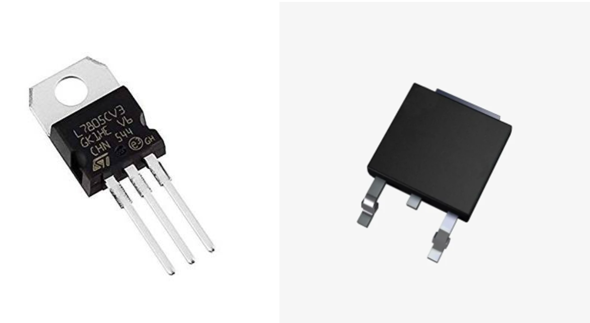
These voltage regulators mostly come in TO-220 and TO-92 packages suitable for DIY and breadboard prototyping projects. It also comes in surface-mount packages to use in printed circuit board designs.
IC 7805 as a Voltage Regulator
By definition, a voltage regulator is an electronic device that maintains a constant voltage across its output terminals regardless of the voltage fluctuations at the input side. There are many such voltage regulators available, such as the LM317. However, 7805 provides a fixed 5V output, and LM317 is an adjustable voltage regulator whose output can be adjusted by selecting the appropriate external resistor values.
The 7805 voltage regulator gives a constant 5V output with a maximum of 1A current and 2A with proper heat sinking. The maximum input voltage range of the 7805 is between 7V and 32V. The 7805 voltage regulator belongs to the 78 series, which denotes the positive output voltage, and 05 indicates the 5V output. On the other hand, the 7905 series provides a constant negative 5V at the output regardless of the fluctuations on the input side.
IC 7805 Voltage Regulator – IC Marking and Meaning
| IC Marking | Meaning |
|---|---|
| 78 | Indicates positive output voltage |
| 05 | Indicates the +5V output |
Working Operation of IC 7805:
The IC 7805 works on the principle of linear voltage regulation. As discussed earlier, linear voltage regulators work by resistive voltage drop.
Step 1:
In the first step, the unregulated input voltage is applied across the input terminal (PIN 1) of the 7805. The input voltage should be greater than 5V and between 7V and 35V.
Step 2:
In the internal circuit of 7805, there is a feedback loop, a pass transistor, and a reference voltage generator. The reference voltage generator produces a +5V constant voltage. The feedback loop continuously compares the input voltage with the reference voltage and adjusts the internal resistance accordingly. The reference voltage is 5V, and the actual voltage is the voltage that is applied at the input terminal of the regulator.
Step 3:
The feedback loop continuously monitors the output voltage, and if the output voltage fluctuates from the reference voltage, it immediately adjusts it to +5V using the pass transistor resistance.
Step 4:
The regulated output voltage is provided at the output terminal (PIN 3) of the 7805 IC. This output pin is then used in an external circuit that requires the constant 5V input voltage to function.
Step 5:
This regulator also consists of various protection features, such as thermal shutdown and short circuit protection, to encounter any hazardous situation.

IC 7805 Voltage Regulator – PIN Configuration
| PIN Number | PIN Name | Function |
|---|---|---|
| PIN 1 | Input | This is the input PIN that receives the unregulated DC voltage. (This voltage is typically between 7 and 32V). Refer datasheet for the exact input voltage range. |
| PIN 2 | GND | This is the GND PIN that acts as the return path for both input and output. |
| PIN 3 | Output | This is the output PIN that continuously regulates the constant +5V output regardless of the change in the input voltage. |
Tips:
It is recommended to place the capacitor at the input and output side with reference to PIN 2. The input capacitor is use to filter noise and suppress the power supply transients. For printed circuit board designs, always place the capacitor close to the input (PIN 1) and GND (PIN 2) to minimize electric and magnetic interference. The output capacitor is use to prevent ripple content and ensure smooth DC voltage output.
IC 7805 Voltage Regulator – Typical Values of Capacitors
| Capacitor Position | Typical Value |
|---|---|
| Input side Capacitor | 0.33 µF |
| Output side Capacitor | 0.1 µF |
Technical Specifications & Parameters
The 7805 voltage regulator is a simple three-terminal device that can be integrated with circuits easily. However, understanding the technical specifications and parameters of 7805 is essential for engineers to effectively integrate it into the electronic circuits.
Technical Specification of 7805 Voltage Regulator
| Parameter | Value | Function |
|---|---|---|
| Output Voltage | 5V | 7805 provides the constant 5V output at PIN 3 |
| Output Tolerance | ±2% – ±4% | Output voltage can vary between 4.8V and 5.2V, depending on load |
| Input Voltage Range | 7V – 35V | Acceptable input voltage range for 7805 regulators |
| Output Current | 1A typically, 1.5A with heat sink | Maximum output current range 7805 offers is 1.5A |
| Dropout Voltage | 2V | Minimum voltage required for regulation (Vin – Vout) |
| Line Regulation | Typically 5 – 50mV | Change in Vout with respect to Vin |
| Load Regulation | Typically 15 – 50mV | Change in Vout with respect to output current |
| Ripple Rejection Ratio | 78dB | Ability of 7805 to reject ripple voltage on output |
| Short Circuit Current Limit | 1.5A | Built-in feature to limit current beyond 1.5A for safe operation |
Tips:
When using this regulator in your circuit, it is important and recommended to use the regulator within these limits. If any parameter value exceeds the manufacturer-specified limit will cause the circuit to misbehave or cause circuit failure. It is therefore always use the IC 7805 regulator within the specified limit and consult the datasheet for the exact range for your specific regulator or manufacturer.
Circuit Design with IC 7805
As we know, the 7805 is a three-terminal device with one input, one output, and one common GND. This section will cover the basics of 7805 voltage regulator circuit design. The basic design includes the selection of appropriate input, output, capacitor power dissipation, heat sinking considerations, line and load regulations calculations.
The circuit design with 7805 typically has a +5V fixed output voltage, input voltage between 7V and 35V, and a maximum 1.5A output current.
Problem:
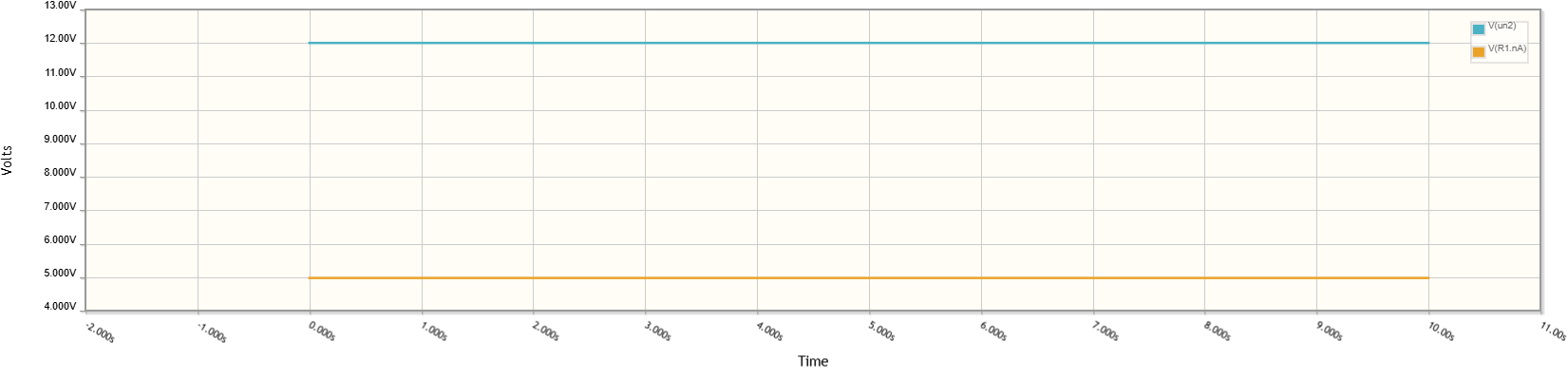
For the design explanation, let’s assume we need to use 7805 regulators in the circuit, and the requirements are +5V output voltage with a maximum of 1A output current, and the input voltage is 12V. The dropout voltage is 2V as per the datasheet.

We know that from the datasheet, the dropout voltage is 2V for the 7805 voltage regulator. Therefore, the minimum input must be;
\[ V_{in(min)} = V_{out} + V_{drop} \]
\[ V_{in(min)} = 5V + 2V \]
\[ {v_in(min)} = 7V \]
This satisfies our problem because we have an input voltage of 12V.
Load Regulation:
The load regulation of 7805 is its ability to maintain a fix 5V output voltage when the load current varies. A low value of load regulation indicates good regulation because it shows that the output has a very small change in output when the load current changes.
\[
\text{Load Regulation} = \frac{V_{NL} – V_{FL}}{V_{FL}} \times 100\%
\]
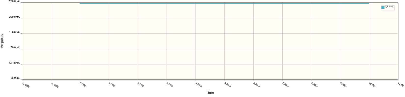
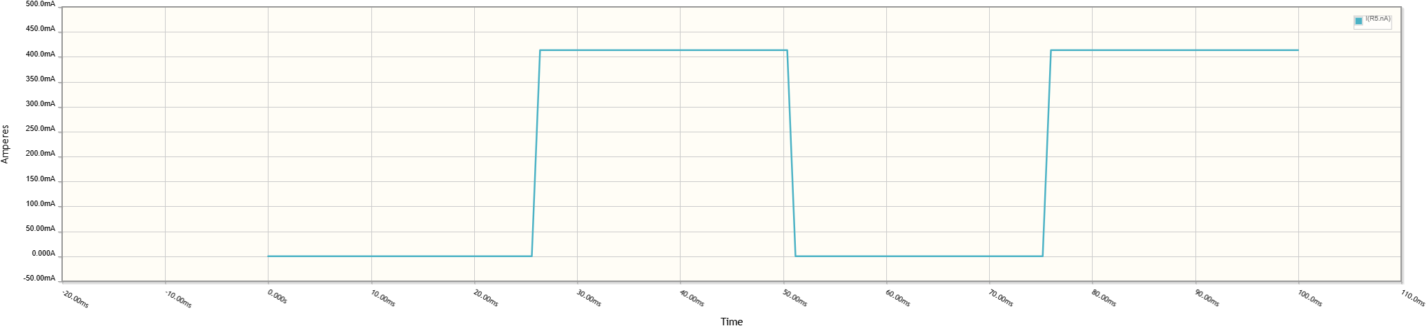
For our example, the output current is 250mA as shown in the graph. The datasheet states that for a 250mA current, the load regulation is 5mV. That means at no load, the regulator gives the 5V fixed output voltage. But at 250mA, the output changes by 5mV, which means 4.995V at the output.
\[
\text{Load Regulation} = \frac{5V – 4.955V}{4.955V} \times 100\%
\]
\[
\text{Load Reg.} = 0.10\%
\]
Power Dissipation:
One of the important parameters in 7805 voltage regulator design consideration is power dissipation because it gives the information on how much energy is being wasted in the form of heat to maintain the constant 5V output. This information is important because it helps the designer to choose the appropriate heat sink if the heat dissipated exceeds from certain limit.
\[
P_{\text{diss}} = (V_{in} – V_{out}) \times I_{out}
\]
In the graph, it is known that the output current for our example is 250mA, the input voltage is 12V, output voltage is 5V. Therefore;
\[
P_{\text{diss}} = (12V – 5V) \times 250mA
\]
\[
P_{d} = 1.75 \, \text{Watt}
\]
Therefore, in our design, the 7805 regulators will dissipate 1.75 watts of energy as heat.
Output Power:
\[
P_{\text{out}} = V_{\text{out}} \times I_{\text{out}}
\]
\[
P_{\text{out}} = 5V \times 0.25A
\]
\[
{\text{Output Power}} = 1.25 \, \text{Watts}
\]
Input Power:
\[
P_{\text{in}} = V_{\text{in}} \times I_{\text{in}}
\]
\[
P_{\text{in}} = 12V \times 0.25A
\]
\[
{\text{Input Power}} = 3.0 \, \text{Watts}
\]
\[
{\text{Input Power}} = P_{\text{out}} + P_{\text{diss}}
\]
\[
3 \, \text{Watts} = 1.25 \, \text{Watts} + 1.75 \, \text{Watts}
\]
Heat Sink Calculation:
Whether or not a heat sink is required for the specific design depends on the heat dissipation and output power. In our specific example, the heat dissipation is . The normal operating temperature is 0°C to 125°C (refer datasheet).
With no heat sink junction formula, we came to know that;
\[
T_{j} = T_{a} + P_{\text{diss}} \times \theta_{JA}
\]
Where Ta is the ambient temperature, Tj is the junction temperature, is junction to ambient thermal resistance $^\circ C/W$. Typically, for a TO-220 package, it is $50\,^\circ C/W$ Therefore;
\[
T_{j} = 25^{\circ} + 1.75 \times 50
\]
\[
T_{j} = 112.5^{\circ}
\]
This temperature indicates that it is in the range of operating temperatures.
However, when the ambient temperature is $40^\circ$
\[
T_{j} = 40^{\circ} + 1.75 \times 50 = 127.5^{\circ}C
\]
This indicates that the junction temperature rises above the maximum operating limit, and a small heat sink is required. The heat sink calculation for this temperature is therefore $\theta_{SA}$
(sink to ambient thermal resistance);
\[
\theta_{SA} = \frac{T_{j,\text{max}} – T_{a}}{P_{diss}}
\]
\[
\theta_{SA} = \frac{125^{\circ} – 40}{1.75} = 48.57^{\circ}C/W
\]
So, the heatsink must have $\theta_{SA} \leq 48.57 \, ^\circ\text{C}/\text{W}$ to make the junction temperature below $125^\circ$.
Efficiency:
The linear regulators, like 7805, have low efficiency because they dissipate energy in order to maintain the fixed voltage at the output. So, before using it in your design, ensure how much you can compromise on the efficiency.
\[
\eta = \frac{P_{out}}{P_{in}} \times 100\%
\]
Plug in the Pout and Pin calculated earlier to get the efficiency of 7805 for our problem.
\[
\eta = \frac{1.25 \,\text{watts}}{3 \,\text{watts}} \times 100\%
\]
\[
\eta = 41.6\%
\]
Common Circuit Applications with IC 7805
In this section, I will explain some common applications of the IC 7805 voltage regulator and explain how the 7805 regulator contributes to getting the required results.
Constant Current regulator with 7805
The 7805 voltage regulator can be configured to work as a constant current regulator. This can be achieved by simply placing a load resistor R1 in series with the output. The output current can be controlled and regulated with the resistor R1.
For instance, to regulate the constant 50mA current at the output, we need to find the value of resistor R1.

\[
I_{out} = \frac{V_{out}}{R_1}
\]
\[
0.05 = \frac{5V}{R_1}
\]
\[
R_1 = 100 \,\Omega
\]
USB charging circuit with 7805
The 7805 regulator can be configure to create a USB charging circuit. A typical USB consists of four PINS. PIN 1 for VCC (5V), PIN 2 and PIN 3 are for data+ and data-, and PIN 4 is GND.

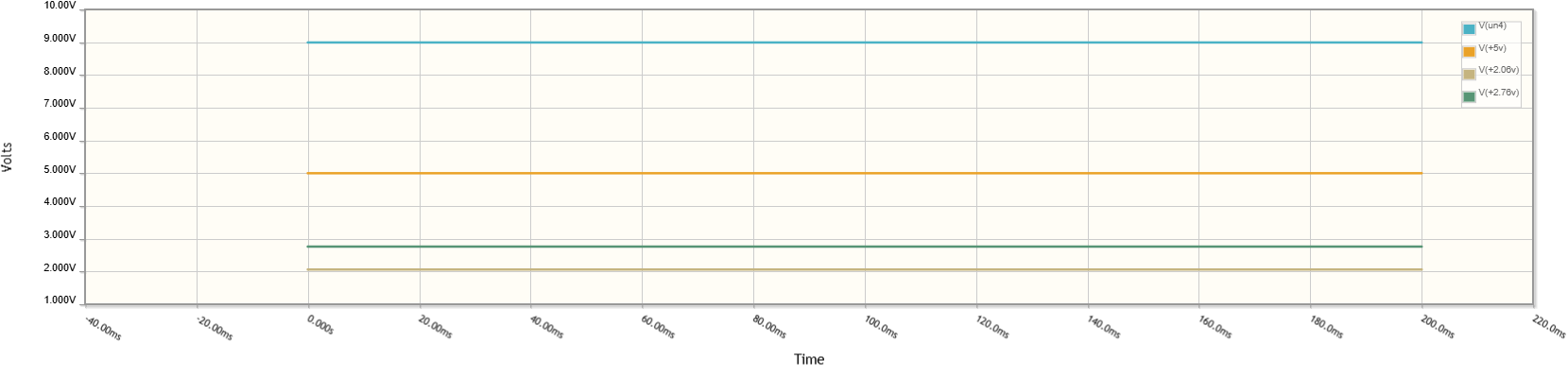
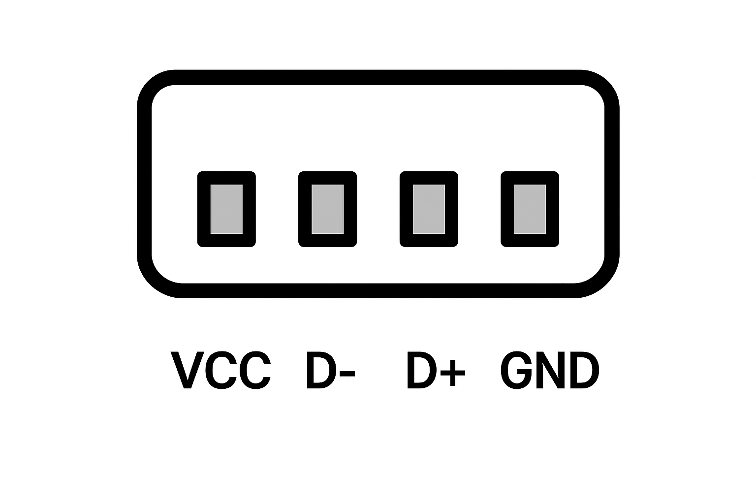
We connect the 5V output to the VCC of the USB and the GND pin of the regulator to the USB pin 4. The voltage levels of 2.06 and 2.76 volts are connected with the D+ and D- PINS of USB, respectively.
Limitations and Advantages of IC 7805
In voltage-sensitive devices such as microcontrollers, operational amplifiers such as LM358 and others require a fixed input voltage. In such cases, the 7805 voltage regulator provides the fixed output without voltage fluctuations. However, these voltage regulators do have some limitations, which are shown in the figure below.

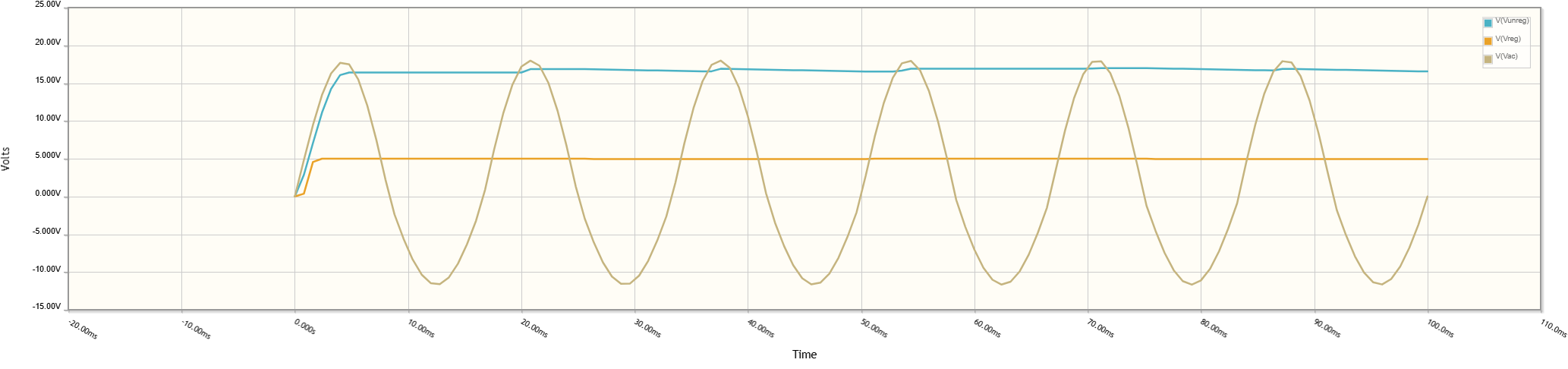
Simulation Results: IC 7805 115VAC-5V Power Supply Design
In this section, I will explain the design and simulation of the power supply circuit with 7805. The AC voltage of 115VAC is fed into the step-down transformer to step down the AC input voltage. The AC voltage is step down to 17VAC. This AC voltage passes through the bridge rectifier circuit to convert the AC voltage into a pulsating DC voltage. The pulsating DC voltage or unregulated DC voltage is use as an input to the 7805 voltage regulator to make this unregulated voltage a fixed constant 5V DC voltage. The output at the 7805 is further filter out using the smoothing capacitor to remove the ripple content from the output and make it pure, constant 5V DC.

Conclusion
To sum up, 7805 is a simple and versatile voltage regulator that is most commonly use in electronic circuits that require a constant 5V for their proper operation, such as microcontrollers, GSM modules, mobile adaptors, operational amplifiers, and communication modules. Their linear regulation nature makes them cost cost-effective and reliable solution for DIY, prototyping projects, and PCB projects. With a proper understanding of its core parameters, load regulation, power dissipation, heat sink, and efficiency, one can easily integrate it into its electronic circuits.
Frequently Asked Questions (FAQ)
Q1. What is the typical cost of a 7805 voltage regulator?
These are the most common and low-cost regulators. Typically, available from 0.2$ to 1$, depending on the quality and brand.
Q2. What is the average lifespan of a 7805 regulator?
If use within the specified limits as identified by the manufacturer, these regulators can last up to more than 20 years.
Q3. What is the role of the input/output capacitor in the 7805 regulator circuit?
The input capacitor in 7805 is used to remove the high-frequency oscillations and noise coming from the supply. The output capacitor is use to remove the ripple content from the voltage to make it pure DC.
Q4. Why do we require a heat sink in 7805?
When the power dissipation of the regulator exceeds the specified thermal limits. We require a heat sink to make it cool and get it under the specified operating temperature.
Q5. Which is better, LM317 or 7805?
Both regulators have their own pros and cons, and selecting which one is better depends on the specific application type. If the application requires fix 5V with a simple circuit, 7805 is prefer in such cases. However, if the application requires an adjustable voltage with no restriction on circuit complexity, LM317 is prefer in such cases.