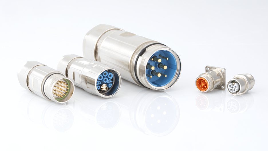
If you’ve ever opened up an industrial control panel, traced a sensor cable, or worked on a piece of aerospace hardware, you’ve almost certainly come across circular connectors.
These round, multi-pin connectors are everywhere. They carry power, signals, and data between cables, panels, sensors, and equipment, often in environments that would damage a less durable connector within weeks.
At their core, circular connectors all do the same job. They create a secure, repeatable connection that can be mated and unmated reliably while standing up to vibration, moisture, dust, and temperature changes.
You’ll also see them called circular electrical connectors. The parts and purpose are the same. This is simply the more formal term commonly used on datasheets.
However, “circular connector” is an umbrella term. It covers a wide range of connector families.
These include M8 and M12 sensor connectors, MIL-SPEC connectors built for aerospace and defence, plastic and metal-shell industrial connectors, hermetic feed-throughs, and many others.
Across the circular connector market, connector choice usually follows the application.
For example, industrial automation often uses M8, M12, and IP-rated connectors. By contrast, aerospace and defence applications are more likely to use standardised MIL-SPEC connector families.
This guide explains what circular connectors are, the main types available, how pin count and ratings affect your choice, and what to consider during assembly and soldering.
Whether you’re specifying a new design or replacing a connector that has reached the end of its service life, this guide provides a useful starting point.
What Are Circular Connectors and How Do They Work?
At a basic level, a circular connector is a two-piece interface.
It includes a circular plug connector, also called a circular connector plug, and a receptacle. The two halves come together to complete an electrical circuit.
Inside the cylindrical shell, contacts sit in a precise pattern. Meanwhile, an insert holds them in the correct position.
This arrangement ensures that every pin lines up with its matching socket whenever the connector is mated.
Keying is what makes this reliable.
A keyway or alignment notch on the shell allows the plug to mate in only one orientation. This prevents incorrect wiring and protects the contacts during connection.
Many circular connectors also use a scoop-proof shell design.
The shell guides the contacts into position before the pins can touch an incorrect surface or become damaged.
Once both halves are aligned, they must remain securely connected. This is where the locking mechanism comes in.
Depending on the connector family, for example, the locking system may use:
- A threaded coupling nut
- A bayonet twist-lock
- A breech-lock ring
- A push-pull quick-disconnect
However, each design has its own advantages and limitations.
For instance, threaded couplings usually perform well under vibration, but they take longer to mate and unmate.
By comparison, push-pull connectors are faster and easier to operate with one hand. However, they may not always be the preferred option for severe vibration.
It is also important to remember that the connector itself is only one part of the complete system.
A full circular connector assembly may include:
- A cable or panel receptacle
- Shell
- Insert
- Contacts
- Environmental seals
- Backshell
- Strain-relief components
- Cable-management accessories
This is why shell size, mounting style, and fastening method matter just as much as pin count when selecting a connector.
Main Parts of a Circular Connector
Before comparing the different connector families, it helps to understand the main parts inside a circular connector.
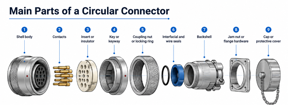
| Part | Function |
| Shell body | Houses and protects the internal components |
| Contacts | Carry power, signal, or data between the mated halves |
| Insert or insulator | Holds contacts in their correct positions and spacing |
| Key or keyway | Prevents mismating and keeps the orientation consistent |
| Coupling nut or locking ring | Secures the plug and receptacle together |
| Interfacial and wire seals | Resist dust, moisture, and other contaminants |
| Backshell | Provides strain relief, shielding, and cable routing |
| Jam nut or flange hardware | Allows panel or bulkhead mounting |
| Cap or protective cover | Protects an unmated connector from dirt and damage |
At this stage, two points are especially important.
Firstly, circular connector accessories are not an afterthought.
Backshells, caps, seals, adapters, splitters, and EMI filters often determine whether an assembly survives years of vibration and washdown cycles or fails within months.
A circular connector backshell protects the cable entry point and provides strain relief.
A circular connector cap protects exposed contacts when the connector is not mated.
Secondly, accessory compatibility varies between connector families.
Standard circular connector accessories may not be interchangeable with MIL-SPEC accessories.
Circular connector contacts may also differ in size, material, plating, and retention method, even when the shell size looks similar.
For that reason, it is worth checking the availability of compatible accessories before choosing a connector family.
Common Circular Connector Types
Circular connectors come in more shapes and sizes than many people expect.
Beyond the basic plug-and-socket design, there are connector families specifically for sensors, automation equipment, outdoor systems, aerospace platforms, and compact devices where there is a limit for weight and space.
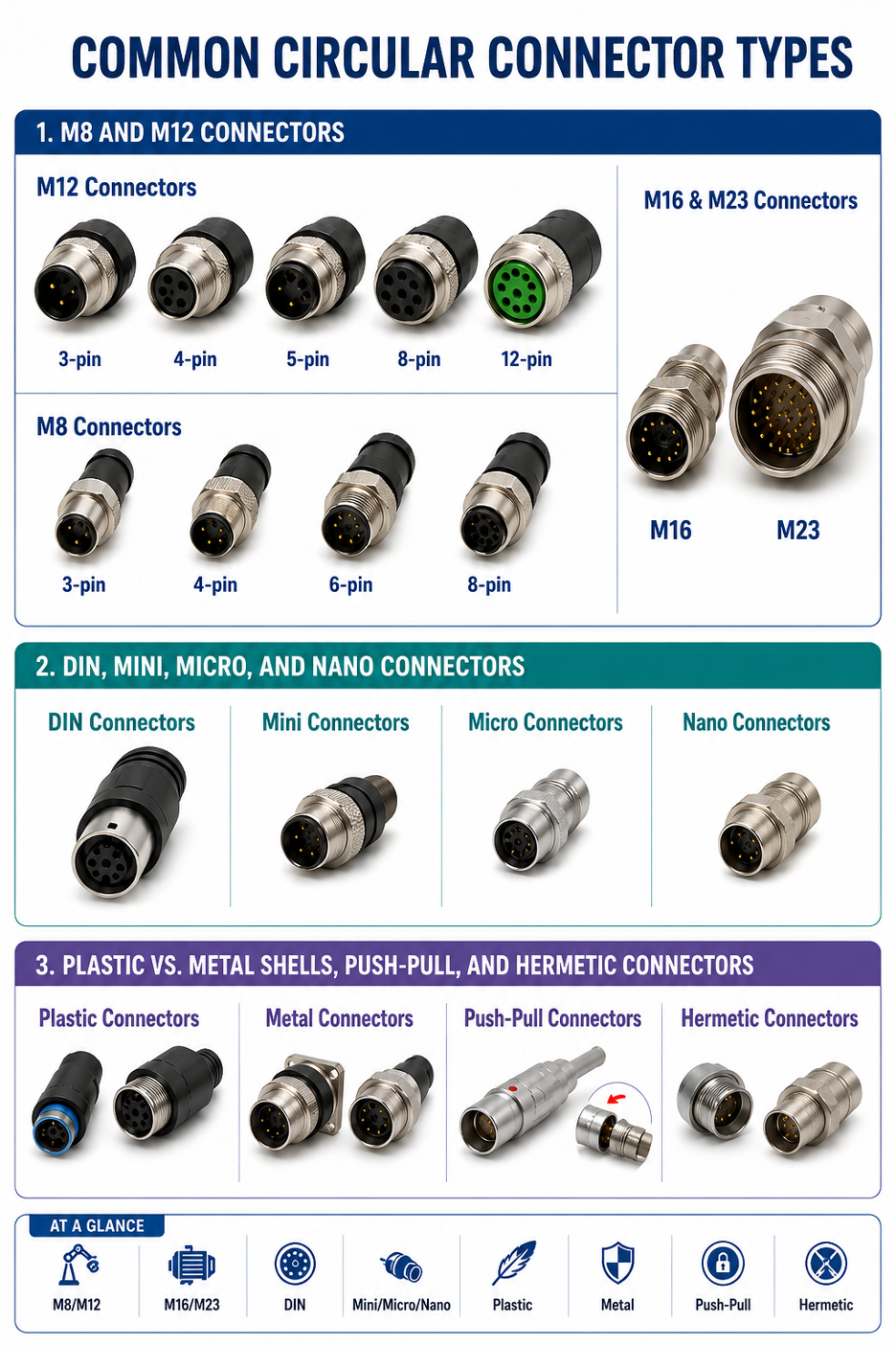
M8 and M12 Connectors
The M12 circular connector and M8 circular connector are among the most common choices in industrial automation.
For example, they are widely used for sensors, actuators, field I/O devices, and machine connections.
Their popularity is largely due to several practical advantages. In particular, they are compact, easy to seal, and available in many configurations for low-voltage power, signals, and data.
M12 connectors commonly come in:
- 3-pin
- 4-pin
- 5-pin
- 8-pin
- 12-pin configurations
In most cases, A-coding is used for general sensor and power applications. Meanwhile, B, D, and X coding are used for specific systems such as fieldbus communication and industrial Ethernet.
The coding prevents the wrong cable from being connected to an incompatible port.
M8 connectors cover similar applications but use a smaller housing.
They are also suitable for compact sensors, lighter signal loads, and device-side connections where space is limited.
Common M8 configurations include:
- 3-pin
- 4-pin
- 6-pin
- 8-pin versions
However, applications requiring more contacts, higher current, or a mixture of power, signals, and data may need larger connectors.
In such cases, the M16 circular connector and M23 circular connectors are common options.
For example, they are often used in motors, servo systems, encoders, motion-control equipment, and industrial machinery where M8 or M12 connectors do not provide enough capacity.
DIN, Mini, Micro, and Nano Connectors
Circular DIN connectors are an older standardised connector family, but they remain common in several applications.
They can still be in:
- Audio equipment
- Legacy industrial systems
- Instrumentation
- Control equipment
An 8-pin circular DIN connector, for example, is used for interfaces that require several signal connections.
By contrast, mini, micro, and nano circular connectors serve compact applications at the other end of the size range.
As a result, these smaller connector families are well suited to systems where every gram and millimetre matters.
Miniature circular connectors and micro miniature circular connectors are often used in:
- Aerospace equipment
- Portable instruments
- Medical devices
- Compact electronic systems
- Test and measurement equipment
These connectors can use the same threaded, bayonet, or push-pull locking methods found on larger circular connectors, but in a much smaller package.
Plastic vs. Metal Shells, Push-Pull, and Hermetic Connectors
Shell material is one of the first choices to make when selecting a circular connector.
Circular plastic connectors are generally lighter and more affordable.
Many use removable contacts and replaceable coupling components, which can make field repair easier.
They are often suitable for general industrial, medical, and electronic applications where low weight and lower cost matter more than maximum shielding.
Metal circular connectors offer greater mechanical strength.
They also provide better EMI shielding, which is important for sensitive signal and data connections.
Metal shells are commonly used in:
- Aerospace
- Defence
- Transportation
- Heavy industrial machinery
- Communication equipment
In comparison, circular push-pull connectors use a different locking method.
Instead of rotating a thread or bayonet mechanism, the user pushes the connector to mate it and pulls a sleeve to release it.
As a result, the connector is fast and intuitive to use.
Push-pull connectors work well in tight spaces and applications with frequent connection and disconnection cycles.
However, the main trade-off is lower retention strength.
Threaded and bayonet connectors generally provide stronger mechanical retention under severe vibration.
Finally, hermetic circular connectors form a separate category.
They use glass-to-metal seals or similar constructions to create a pressure-tight barrier.
This is different from a standard waterproof connector.
Hermetic connectors protect against gas leakage, fluid leakage, and pressure differences.
They are commonly used in:
- Aerospace systems
- Subsea equipment
- Vacuum systems
- Medical systems
- Military equipment
- Pressure feed-through applications
When an application requires leak-tight performance or must withstand a pressure difference, circular hermetic connectors should be considered instead of treating the problem as ordinary waterproofing.
Pin Counts and Common Uses
Pin count is usually one of the first ways engineers narrow down their connector options.
The circular connector chart below provides general guidance.
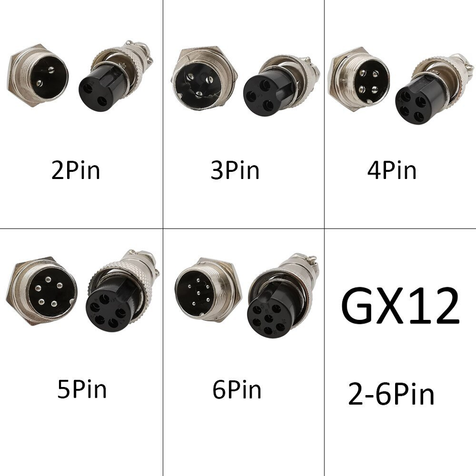
However, exact uses and configurations vary by manufacturer and connector series.
| Pin Count | Typical Use |
| 2-pin circular connector | Simple DC power feeds and basic device connections |
| 3-pin circular connector | Power plus ground or basic control and signal loops |
| 4-pin circular connector | Sensors, low-voltage control, or combined power and signal |
| 5-pin circular connector | Sensors, actuators, and small automation interfaces |
| 6-pin circular connector | Multi-signal wiring or mixed control circuits |
| 7-pin circular connector | Mid-density control and industrial connections |
| 8-pin circular connector | Signal-heavy DIN or automation interfaces |
| 9-pin circular connector | Instrumentation and higher-density control layouts |
| 12-pin circular connector | Compact multi-signal systems and dense cable assemblies |
| 19-pin circular connector | Higher-density industrial or vehicle-style layouts |
| 32-pin circular connector | Dense signal and control assemblies requiring many contacts |
For simple power applications, these products may be listed as circular power connectors.
For example, a 2-pin circular power connector, sometimes written as circular connector 2 pin, is a common choice for basic DC connections.
A circular 6 pin connector is often used when several signal or control wires must pass through one connection point.
Some suppliers may also use the term circular terminal connector, especially when the termination type is more important than the number of pins.
However, pin count alone does not tell you whether a connector is suitable.
Two connectors with the same number of positions may have very different:
- Current ratings
- Voltage ratings
- Contact sizes
- Termination methods
- Shell sizes
- Environmental ratings
Therefore, a search for a 6-pin circular connector or 8-pin circular connector should only be the starting point.
You must then check the contact rating, shell size, keying, termination method, and environmental specification.
How to Choose the Right Connector
Once you have identified a suitable connector family and approximate pin count, the next step is to review the technical ratings.
These specifications determine whether the connector will perform reliably in the intended application. Therefore, the selection process should start with broad application requirements and gradually move toward specific technical details.
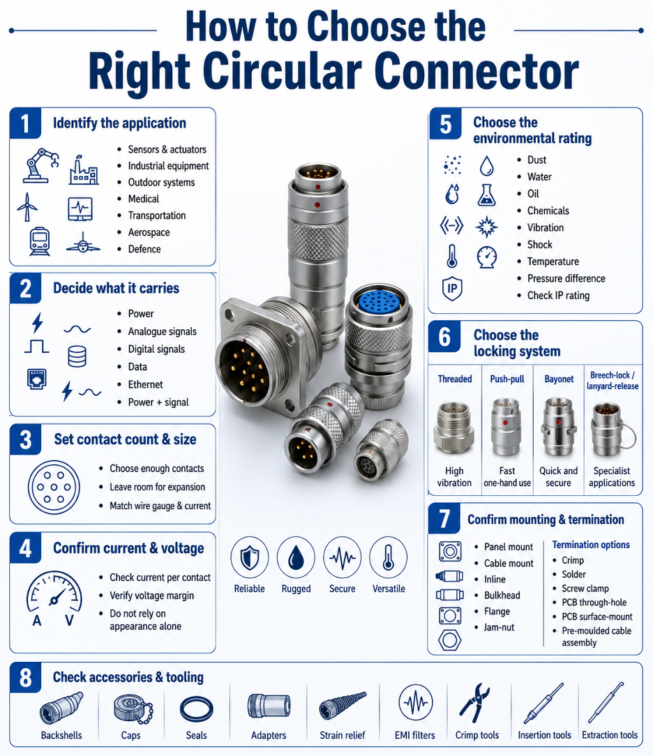
1. Identify the application
Determine whether the connector will be used in:
- Sensor or actuator systems
- General industrial equipment
- Outdoor systems
- Medical equipment
- Transportation
- Aerospace
- Defence
2. Decide what the connector will carry
Identify whether the connector must carry:
- Power
- Analogue signals
- Digital signals
- Data
- Ethernet
- A combination of power and signals
3. Set the contact count and contact size
First, choose enough contacts for the current wiring requirements.
In addition, you may want to leave one or two spare contacts for future expansion.
Finally, ensure that the contact size is suitable for the wire gauge and current requirement.
4. Confirm current and voltage ratings
Check the current rating for each contact.
Do not assume the listed connector rating applies equally under all contact-loading conditions.
Also confirm that the voltage rating provides enough safety margin above the system voltage.
5. Choose the environmental rating
Consider exposure to:
- Dust
- Water
- Oil
- Chemicals
- Vibration
- Shock
- High or low temperatures
- Pressure differences
For wet or dusty environments, also check the tested IP rating.
Water and dust protection should be confirmed using tested IEC 60529 ingress protection classifications, rather than relying only on the word “waterproof.”
6. Choose the locking system
The correct locking system depends on vibration, maintenance, and how often the connector will be disconnected.
Threaded connectors are generally suitable for high-vibration or safety-critical applications. Push-pull connectors are useful where fast, one-handed operation is required.
Bayonet connectors, meanwhile, provide a balance between quick mating and secure retention.
By comparison, breech-lock and lanyard-release designs are more common in specialised military, aerospace, or blind-mate applications.
7. Confirm mounting and termination
Determine whether the connector needs to be:
- Panel mounted
- Cable mounted
- Inline
- Bulkhead mounted
- Flange mounted
- Jam-nut mounted
Then choose a suitable termination style.
Options include:
- Crimp
- Solder
- Screw clamp
- PCB through-hole
- PCB surface-mount
- Pre-moulded cable assembly
8. Check accessories and tooling
Make sure the required accessories are available.
These may include:
- Backshells
- Caps
- Seals
- Adapters
- Strain-relief components
- EMI filters
- Crimp tools
- Insertion tools
- Extraction tools
You can choose compatible circular connector backshells and cable clamps to provide strain relief, shielding, and secure cable routing.
MIL-SPEC and Harsh-Environment Connectors
For this reason, applications in aerospace, defence, and other mission-critical environments often use MIL-SPEC circular connectors.
These may also be called circular MIL-SPEC connectors, military circular connectors, or circular military connectors.
In these applications, it is important to start with the required standard rather than choosing a connector only by its shape.
The MIL-DTL-5015 circular connector is a long-established medium-density connector family.
It supports many power and signal insert arrangements.
Depending on the product series, it may use threaded or reverse-bayonet coupling.
MIL-DTL-38999 connectors, also known as 38999 circular connectors or MIL 38999 circular connectors, are a more modern military and aerospace family.
They are known for:
- Rugged construction
- Corrosion resistance
- High contact density
- Reliable power, signal, and data connections
- Environmental sealing
- Multiple shell and coupling options
MIL-DTL-38999 families may also include military hermetic circular connector variants for pressure-sealed applications.
Together, MIL-DTL-5015 and MIL-DTL-38999 cover many of the products people refer to as aerospace MIL-SPEC circular connectors.
However, the standard numbers should not be treated as interchangeable terms.
For a MIL-SPEC connector, verify:
- Specification family
- Connector series
- Shell style
- Insert arrangement
- Contact type
- Contact size
- Keying or polarisation
- Accessory interface
- Environmental class
These details can vary considerably within the same standard.
Accessories are especially important in MIL-SPEC systems.
Backshells qualified to standards such as AS85049 are designed for specific connector families.
Using the correct backshell affects:
- EMI shielding
- Cable strain relief
- Environmental protection
- Mechanical reliability
MIL-SPEC circular connector accessories and MIL-SPEC circular connector contacts are often intended to work as a qualified system.
Replacing them with generic parts, even when those parts physically fit, may affect the performance or certification of the full assembly.
When sourcing replacement components or building a new harness, confirm compatibility using the complete connector part number, not only the general family name.
Cable Assembly, Soldering, and Practical Tips
Many circular connector cable assembly questions focus on how to install or remove the connector without damaging it.
The following workflow applies to many connector families, although the exact process should always come from the manufacturer’s instructions.
General Assembly Workflow
- First, confirm the exact connector family, shell size, insert arrangement, and contact type.
- Next, check the cable diameter and accessory fit before terminating any wires.
- Then, choose the correct termination method, such as crimp, solder, screw clamp, PCB, or pre-moulded cable.
- After that, strip the cable according to the manufacturer’s specified dimensions.
- Once the cable is prepared, terminate the contacts using the correct tool or soldering process.
- Next, insert any removable contacts using the specified insertion tool.
- Before completing the assembly, verify the keying, contact position, and strain relief.
- Then, fit the backshell, cap, seal, or shield termination as required.
- Finally, test continuity and insulation before using the assembly.
Soldering a Circular Connector
Not every circular connector is designed for soldering.
Some connector families use crimp contacts, while others contain contacts permanently mounted in the insert.
Before using a soldering iron, confirm that the connector supports solder termination.
If it does, strip the conductor to the specified length.
Lightly pre-tin the wire only if the manufacturer’s instructions allow it.
Apply heat efficiently to the contact.
Avoid overheating the insert, seals, or nearby insulation.
The finished joint should have a clean solder fillet without bridging between contacts.
After assembly, test every connection for continuity.
Also confirm polarity before powering the system.
Where permitted by the assembly design, correctly sized heat-shrink tubing can provide insulation and additional support around terminated wires.
Removing Contacts
Removing contacts incorrectly is a common cause of connector damage. Therefore, always use the insertion or extraction tool specified for the exact connector family.
Importantly, the contact-removal process is not universal. Instead, it may vary between manufacturers and even between connector series from the same manufacturer.
As a result, forcing a contact out with pliers, a screwdriver, or the wrong extraction tool can permanently damage the insert or retention clip.
For military connector families, follow the manufacturer-approved assembly instructions and tools for contact insertion, removal, termination, and accessory installation.
Applications, Manufacturers, and Buying Considerations
Circular connectors and circular cable connector assemblies are used across a wide range of industries.
Common applications include:
- Industrial automation
- Instrumentation
- Transportation
- Medical devices
- Aerospace
- Defence
- Robotics
- Outdoor equipment
- Process equipment
- Communication systems
Industrial circular connectors are especially useful where ordinary connectors may not survive.
Examples include:
- Vibration on factory equipment
- Washdown cycles in food-processing facilities
- Outdoor moisture and dust
- Oil and coolant exposure
- Temperature changes
- Pressure changes at altitude
Common circular connector manufacturers include:
- Amphenol
- TE Connectivity
- AMP
- DEUTSCH
- Binder
- Glenair
- Molex
- Phoenix Contact
- Hirose
- Souriau-Sunbank
Searches for Amphenol circular connectors and DEUTSCH circular connectors are common because these brands have large connector and accessory ranges.
Brand matters because connector families, mating interfaces, accessories, and part availability differ between manufacturers.
Once a connector family has been selected, using compatible backshells, caps, contacts, and seals from the same system can reduce compatibility problems.
When comparing circular connector manufacturers, look beyond the headline IP rating.
Also check:
- Insert arrangement
- Keying
- Contact availability
- Shell size
- Accessory threads
- Tooling requirements
- Lead time
- Long-term availability
The connector standard, shell size, contact arrangement, sealing, and accessory compatibility should guide the decision more than brand loyalty alone.
Waterproof circular connectors also require careful checking.
“Waterproof” is a general marketing description, not a complete technical specification.
IP67, IP68, and IP69K are defined protection ratings.
If sealing is important, ask for the tested IP rating and the conditions under which it applies.
Final Thoughts
Choosing the right circular connector involves more than matching the plug shape or pin count.
You must also check the current and voltage ratings, contact size, shell size, termination method, environmental protection, locking system, mounting style, and accessory compatibility.
For outdoor, industrial, aerospace, or other demanding applications, in particular, pay close attention to sealing, vibration resistance, temperature limits, shielding, and the tested IP rating.
Most importantly, always confirm your choice against the manufacturer’s datasheet. Although two circular connectors may look similar, they can use different keying, pin layouts, contacts, threads, or accessories and may not be compatible.
Flywing Tech offers a broad selection of circular connector, circular cable assemblies, contacts, adapters, backshells, and related accessories.
Need help sourcing the right connector? Browse the available product categories or submit an RFQ with your required part number, contact count, electrical ratings, mounting style, and application details.
Frequently Asked Questions
What are circular connectors?
Circular connectors are round, multi-pin interconnects used to transmit power, data, and electrical signals between cables, panels, sensors, and equipment.
They use a cylindrical shell with contacts arranged inside an insulating insert.
Circular connectors range from small sensor connectors to large military and aerospace interconnects.
What is the difference between a circular connector and a round connector?
In most situations, both terms describe the same general connector shape.
“Round connector” is a more casual term.
“Circular connector” is the standard technical term used when discussing connector families, shell sizes, contact arrangements, locking methods, and industry standards.
What is an M12 connector used for?
M12 connectors are widely used in industrial automation.
They connect sensors, actuators, field I/O devices, motors, and industrial networking equipment.
Different coding types support power, general signals, fieldbus systems, and industrial Ethernet.
Are circular connectors waterproof?
Some circular connectors are waterproof, but others are not.
The level of protection depends on the connector’s IP rating and whether it is properly mated and installed.
Look for a tested rating such as IP67 or IP68 rather than relying only on a general “waterproof” claim.
Where can I find hermetic circular connectors?
Hermetic circular connectors are usually available from manufacturers and distributors specialising in aerospace, military, vacuum, subsea, medical, and pressure-sealed applications.
They use pressure-tight sealing methods, such as glass-to-metal seals, rather than only standard elastomer seals.
How do you remove pins from a circular connector?
First, use the extraction tool specified for the connector family and contact size.
However, the removal procedure differs between manufacturers and connector series.
In addition, some solder-contact connectors use fixed contacts that are not designed to be removed.
How do you solder a circular connector?
First, confirm that the connector uses solder-compatible contacts.
Next, strip the conductor to the specified length.
Then, heat the contact efficiently without overheating the insert or seals.
After soldering, check that the joint is clean and free from bridging.
Finally, test every contact for continuity and verify the polarity after reassembly.
What are MIL-SPEC circular connectors?
MIL-SPEC circular connectors are built to military or aerospace specifications, such as MIL-DTL-38999 or MIL-DTL-5015.
They are designed for reliable operation in demanding conditions.
Typical features include:
- Vibration resistance
- Environmental sealing
- Controlled polarisation
- Rugged shells
- Standardised contacts
- Compatible backshells and accessories
COMMENTS