Introduction
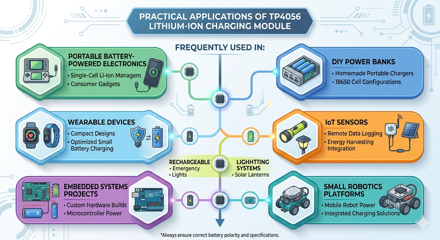
The TP4056 or TPB4056 is one of the most widely used single-cell lithium battery charging ICs because of its simplicity, low cost, and easy integration into battery-powered electronics. From portable IoT devices and wearable electronics to DIY power banks and embedded systems, the TP4056 provides a convenient solution for charging lithium-ion and lithium-polymer batteries using standard USB power sources.
Although numerous TP4056 modules are readily available, designing a reliable hardware implementation requires more than simply connecting a battery and USB connector. Proper input protection, charge current configuration, thermal management, PCB layout, battery protection circuitry, and power path considerations all play an important role in creating a safe and robust charging system.
This guide provides a comprehensive hardware-focused approach to TP4056 circuit design, covering USB input implementation, protection circuits, charging current calculations, PCB layout recommendations, load-sharing techniques, and practical schematic examples. By the end of this guide, you will understand how to design a production-ready TP4056 charging circuit rather than simply using an off-the-shelf module.
Understanding TP4056 Charger IC
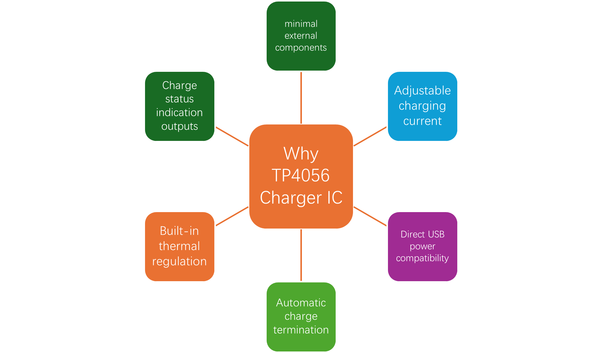
The TP4056 is a complete constant-current and constant-voltage linear charger IC specifically designed for charging single-cell lithium-ion and lithium-polymer batteries. It is commonly used in portable electronics because it requires very few external components while providing a complete battery charging solution.
Unlike complex switching battery chargers, the TP4056 uses a linear charging architecture, making circuit implementation straightforward and reducing design complexity. The IC can directly accept power from a standard 5V USB source, eliminating the need for additional charging controllers in many applications.
The TP4056 operates using a standard CC/CV (Constant Current / Constant Voltage) charging algorithm. During charging, the battery first receives a constant current until the battery voltage approaches the target charging voltage. The charger then gradually reduces charging current while maintaining a fixed output voltage to safely complete the charging process.
The IC is designed specifically for single-cell lithium batteries with a final charging voltage of 4.2V and should not be used directly for multi-cell battery configurations without additional circuitry.
TP4056 Battery Charging IC Pinout
Understanding the function of each TP4056 pin is important before designing the charger circuit. Although the TP4056 requires only a few external components, proper implementation depends on correctly connecting each pin according to its intended function.
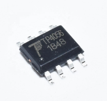
The TP4056 is commonly available in an SOP-8 package and consists of several pins dedicated to power input, battery charging, current programming, control signals, and charging status outputs.
TP4056 Pin Configuration Table
How TP4056 Charging Works
The TP4056 charges lithium-ion and lithium-polymer batteries using a Constant Current / Constant Voltage (CC/CV) charging algorithm. This charging method is widely used because it safely charges batteries while maximizing battery life and preventing overcharging.
Instead of continuously supplying a fixed current throughout the charging cycle, the TP4056 automatically changes charging behavior depending on battery voltage and charging state
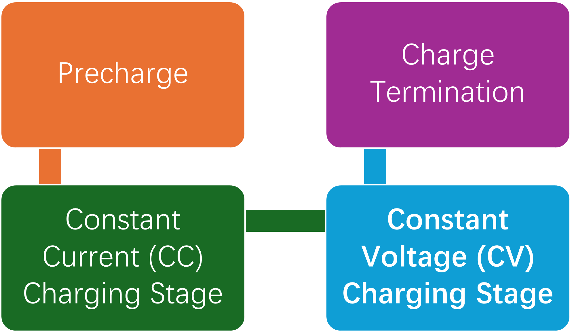
The charging process can be divided into four major stages.
Precharge
When a deeply discharged battery is connected, immediately applying full charging current may damage the battery. To avoid this, the TP4056 first checks the battery voltage. If the battery voltage is below the internal threshold, the charger enters precharge mode.
Constant Current (CC) Charging Stage
After the battery exits precharge mode, the TP4056 enters constant-current charging mode. In this stage, the charger supplies a fixed charging current; the current is determined by the external PROG resistor, and the battery voltage continues to increase. This stage delivers most of the battery capacity and is generally the fastest part of the charging cycle.
Constant Voltage (CV) Charging Stage
Once the battery voltage approaches the target charging voltage (4.2V), the charger changes operating mode. During constant voltage mode, battery voltage is maintained at 4.2V, charging current decreases, and the battery reaches full capacity. This stage prevents excessive voltage from being applied to the battery while allowing the remaining capacity to be filled.
Charge Termination
The TP4056 continuously monitors charging current during constant voltage operation. Charging automatically stops when the charging current falls below the termination threshold. At this point, CHRG pin status changes, STDBY output indicates completion, and battery charging stops automatically. Automatic termination prevents overcharging and improves battery lifespan.
USB Input Design for TP4056
The TP4056 is commonly powered from USB sources because the IC is designed to operate from a 5V input supply. However, simply connecting a USB connector directly to the charger is not always sufficient for reliable operation. Proper USB input design helps improve charging stability, reduce noise, and protect the charger from input disturbances.
The following sections explain how to properly design USB-powered TP4056 charging circuits using both Micro USB and USB Type-C connectors.
USB Power Source Requirements
The TP4056 requires a stable input supply to maintain proper charging operation. Since most designs use USB power, understanding USB limitations is important when selecting charging current and designing the input stage.
Input Voltage Requirements
Typical TP4056 input requirements: recommended operating voltage is 4V–8V, and typical input voltage is 5V USB supply. Using input voltages significantly above 5V increases power dissipation and heating.
Input Filtering Recommendations
To improve stability, place ceramic input capacitors close to the VUSB pin, use short power traces, and reduce cable resistance when using higher charging currents.
USB Type-C Input Design
USB Type-C is increasingly replacing Micro USB because of improved mechanical reliability and wider availability.
The TP4056 still requires only a 5V input supply, but USB Type-C connectors require additional configuration to properly request power.
Why CC Resistors Are Required
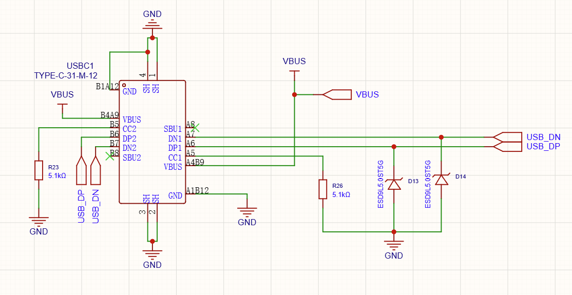
Unlike Micro USB, Type-C connectors do not automatically provide power unless proper configuration is detected. Configuration Channel (CC) pins, i.e., CC1 and CC2, must be configured, and pull-down resistors of 5.1K ohm indicate power sink behavior. Without these resistors, the USB-C power supplies may not provide output voltage.
Basic USB Type-C Implementation
For the simple design of TP4056, connect both CC pins through pull-down resistors, connect VBUS to the TP4056 input, and connect grounds. The typical resistor values are a 5.1kΩ pull-down resistor on CC1 and a 5.1kΩ pull-down resistor on CC2. The USB Type-C circuit implementation is shown below.
Complete TP4056 Hardware Schematic Design
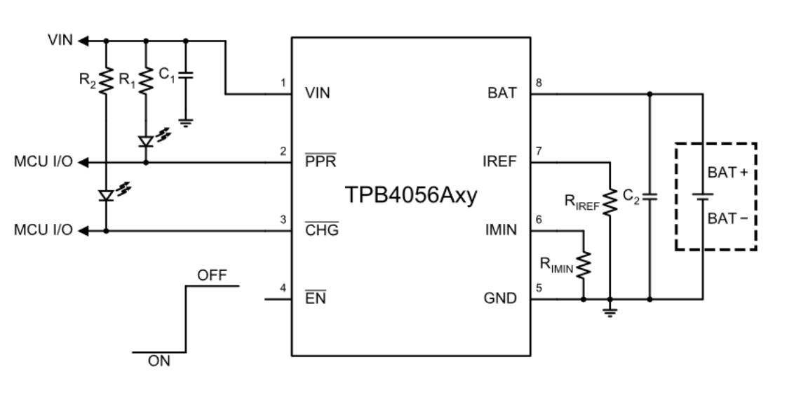
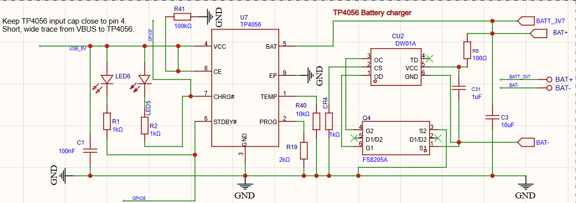
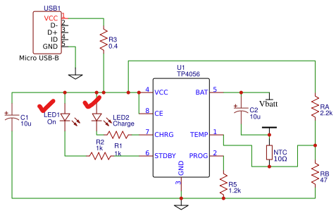
After understanding the charging mechanism and USB input design, the next step is creating a complete hardware implementation. A reliable TP4056 charging circuit requires more than simply connecting power and battery terminals. Proper component selection, filtering, protection circuitry, and layout considerations significantly improve reliability and charging performance. This section covers both the minimum working circuit and a recommended production-ready implementation.
A basic circuit typically contains a TP4056 charger IC, an input capacitor, a programming resistor, a USB power input, and a lithium battery connection.
Minimum Required Components
Setting Charge Current Using PROG Resistor
One of the most useful features of the TP4056 is its adjustable charging current capability. Unlike fixed-current chargers, the TP4056 allows designers to configure charging current using only a single external resistor connected to the PROG pin.
The TP4056 determines charging current using the external programming resistor (RPROG). The following table shows commonly used resistor values and their approximate charging currents.
TP4056 Charging Current vs RPROG Value
Battery Protection Circuit Design
Although the TP4056 is capable of safely charging lithium batteries, the charger IC itself does not provide complete battery protection. Many beginners incorrectly assume that a TP4056 charger automatically protects the battery from all abnormal conditions, but this is not true.
The TP4056 primarily controls the charging process. Additional circuitry is typically required to protect lithium batteries from dangerous operating conditions such as overcharging, excessive discharge, short circuits, and overcurrent events.
For reliable and safe battery-powered designs, battery protection circuitry should be considered an essential part of the overall hardware design.
Why Protection is Required
Lithium batteries require strict voltage and current limits because operating outside safe conditions can permanently damage the battery or create safety risks. Although TP4056 terminates charging, additional protection provides another safety layer.
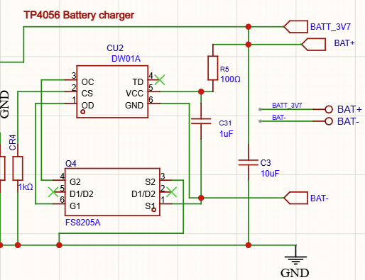
Adding DW01 + MOSFET Protection Circuit
A common solution is adding a dedicated battery protection IC together with dual MOSFETs. The most widely used implementation uses DW01 battery protection IC, Dual MOSFET package, and Battery monitoring circuitry. This protection circuit is commonly found on “TP4056 with protection” modules.
Thermal Design Considerations
Thermal management is one of the most important aspects of TP4056 hardware design because the charger uses a linear charging architecture. Unlike switching regulators, linear chargers dissipate excess power as heat. Improper thermal design can cause excessive temperature rise, reduced charging current, slower charging speed, and unreliable operation.
Many charging problems commonly attributed to defective chargers are actually thermal design problems. Understanding heat generation and proper PCB thermal design helps create a reliable charging circuit.
PCB Thermal Design Recommendations
Proper PCB layout significantly affects charging temperature. Larger copper areas improve heat spreading. It is recommended to connect the thermal pad t large copper region, increase copper around GND pins and avoid isolated thermal pads.
Ground planes improve cooling by distributing heat across larger areas. Therefore, always use a solid ground plane and connect the thermal pad directly to the ground copper. Also, place vias beneath the thermal pad and use multiple small vias instead of one large via.
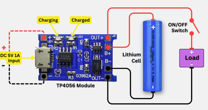
Charge Status LEDs Design
The TP4056 provides dedicated output pins for displaying charging status, allowing simple implementation of visual indicators without requiring additional control circuitry or microcontrollers.
Charge status LEDs are useful because they provide immediate feedback about charger operation and battery charging state. Typical status indication allows users to quickly determine whether charging is active, whether charging has completed, and whether the charger is functioning correctly.
The TP4056 provides two dedicated outputs for this purpose, such as the CHRG pin and STDBY pin. The CHRG output indicates when charging is actively occurring, and the STDBY pin indicates charging completion.
Recap of the TP4056 Charging IC Module
The TP4056 is a widely used single-cell lithium-ion / lithium-polymer battery charging IC designed to simplify USB-based battery charging systems. It provides a complete linear charging solution with constant current (CC) and constant voltage (CV) control, making it highly popular in portable electronics, DIY projects, and embedded systems.
At the core of its operation, the TP4056 manages the entire charging cycle automatically. It begins with precharge for deeply discharged batteries, then moves into constant current mode where the charging rate is set using the PROG resistor. As the battery voltage approaches 4.2V, it transitions into constant voltage mode, gradually reducing current until the battery is fully charged and safely terminating the charge cycle. This automated process eliminates the need for external control logic.
In hardware design, proper implementation of USB input is essential for stable operation. Whether using Micro USB or USB Type-C, the design must ensure proper power delivery, input filtering, and in the case of USB-C, correct CC resistor configuration. These considerations help maintain reliable charging performance and protect the circuit from unstable power sources.
Conclusion
The TP4056 is a practical and widely adopted solution for single-cell lithium-ion and lithium-polymer battery charging, especially in USB-powered electronic systems. Its built-in constant-current/constant-voltage charging algorithm, minimal external component requirement, and automatic charge termination make it an ideal choice for compact and low-cost designs.
However, a reliable TP4056-based system is not just about connecting a battery and USB supply. A proper hardware design must include careful consideration of USB input stability, correct charge current selection through the PROG resistor, and effective thermal management to handle power dissipation. These factors directly influence charging efficiency, safety, and long-term performance.
Frequently Asked Questions (FAQ)
Yes, the TP4056 is commonly used to charge 18650 lithium-ion cells because they are single-cell 3.7V batteries. However, proper protection circuitry should be used for safe operation.
No, the standard TP4056 IC does not include full battery protection. Protection against over-discharge, short circuit, and overcurrent is usually added using a DW01 + dual MOSFET protection circuit.
The basic TP4056 does not support proper load sharing. If a load is connected during charging, it may affect charge termination and battery behavior. A load-sharing or power-path circuit is recommended for such designs.
The charging current depends on the PROG resistor value. Typically, it can be set up to around 1A, but practical designs often use 500mA to 1A depending on thermal conditions and USB supply capability.
Yes, TP4056 can work with USB Type-C as long as the input provides a regulated 5V supply. Proper CC resistors (usually 5.1kΩ) must be used to correctly configure the Type-C port as a power source.
CHRG indicates active charging (usually LOW during charging), while STDBY indicates charge completion (LOW when charging is finished). These pins are often used to drive LEDs.
COMMENTS