What is the SX1276?
The SX1276 is a sub-GHz LoRa transceiver IC from Semtech Corporation. It operates across ISM bands from 137 MHz to 1020 MHz. It achieves a receiver sensitivity of up to −148 dBm. Combined with a +20 dBm power amplifier, it delivers a 168 dB maximum link budget. That makes it one of the longest-range low-power wireless chips commercially available. It supports LoRa, FSK, and OOK modulation modes. Communication over the SPI bus to any microcontroller is straightforward.
| Parameter | Value / Range |
|---|---|
| Frequency Range | 137 MHz – 1020 MHz (ISM bands) |
| LoRa Sensitivity | Up to −148 dBm |
| Max TX Output Power | +20 dBm (PA_BOOST path) |
| Max Link Budget | 168 dB |
| Spreading Factor | SF6 – SF12 (6 programmable levels) |
| Signal Bandwidth | 7.8 kHz – 500 kHz (10 settings) |
| Coding Rate | 4/5, 4/6, 4/7, 4/8 |
| Modulation Modes | LoRa, (G)FSK, OOK |
| Sleep Current | < 200 nA |
| RX Current (active) | ~10.8 mA |
| Supply Voltage | 1.8 V – 3.7 V |
| Package | 28-pin QFN (exposed pad) |
| SPI Interface | Up to 10 MHz, full-duplex |
| FIFO Buffer | 256 bytes |
Why Long-Range, Low-Power Wireless Is Hard
There is usually an obvious tradeoff with different wireless technologies. WiFi offers great speed. Bluetooth is very simple to use. Cellular networks offer access to all corners of the earth. However, none of the current wireless technologies offer a range of kilometers at very low power consumption (microwatt class) without making compromises.
This dilemma is at the very heart of the current IoT (the Internet of Things) revolution, where you want to have remote sensor devices such as soil moisture sensors in far-away agricultural fields, water level gauges on rivers in rural areas, or asset trackers mounted on shipping containers. The challenge is that these devices cannot be connected by wire, and they cannot be frequently recharged. They need to communicate over distances well beyond what can be done using Bluetooth, and they require battery life that would be difficult to achieve with conventional cellular technologies.
Sub-GHz radio communication enables long-range data transmission while maintaining very low power consumption. At lower frequencies, radio signals may propagate greater distances than higher-frequency signals. Lower frequency signals are also capable of penetrating walls and landforms more easily than 2.4 GHz signals. The right modulation scheme (spread spectrum) also allows for the extraction of usable data signals from very noisy environments, which cannot be done with a conventional FSK receiver.
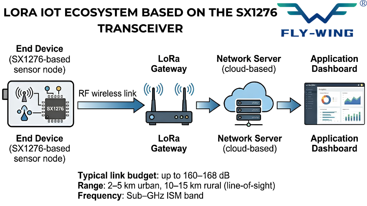
The Semtech SX1276 chip was developed specifically to resolve this issue. It takes advantage of Semtech’s proprietary LoRa (long range) modulation algorithm and produces a single-chip solution for this type of application. The SX1276 quickly became the standard silicon used in all early LoRaWAN networks and is still widely used today with an extensive ecosystem supporting it, including modules, libraries, and certified hardware.
SX1276 Electrical and RF Specifications
The numbers below come directly from the Semtech SX1276/77/78/79 datasheet, Revision 7, dated May 2020. Whenever you are designing hardware, always cross-check against the current datasheet; errata and revision changes do occur.
Frequency Coverage and Regional Variants
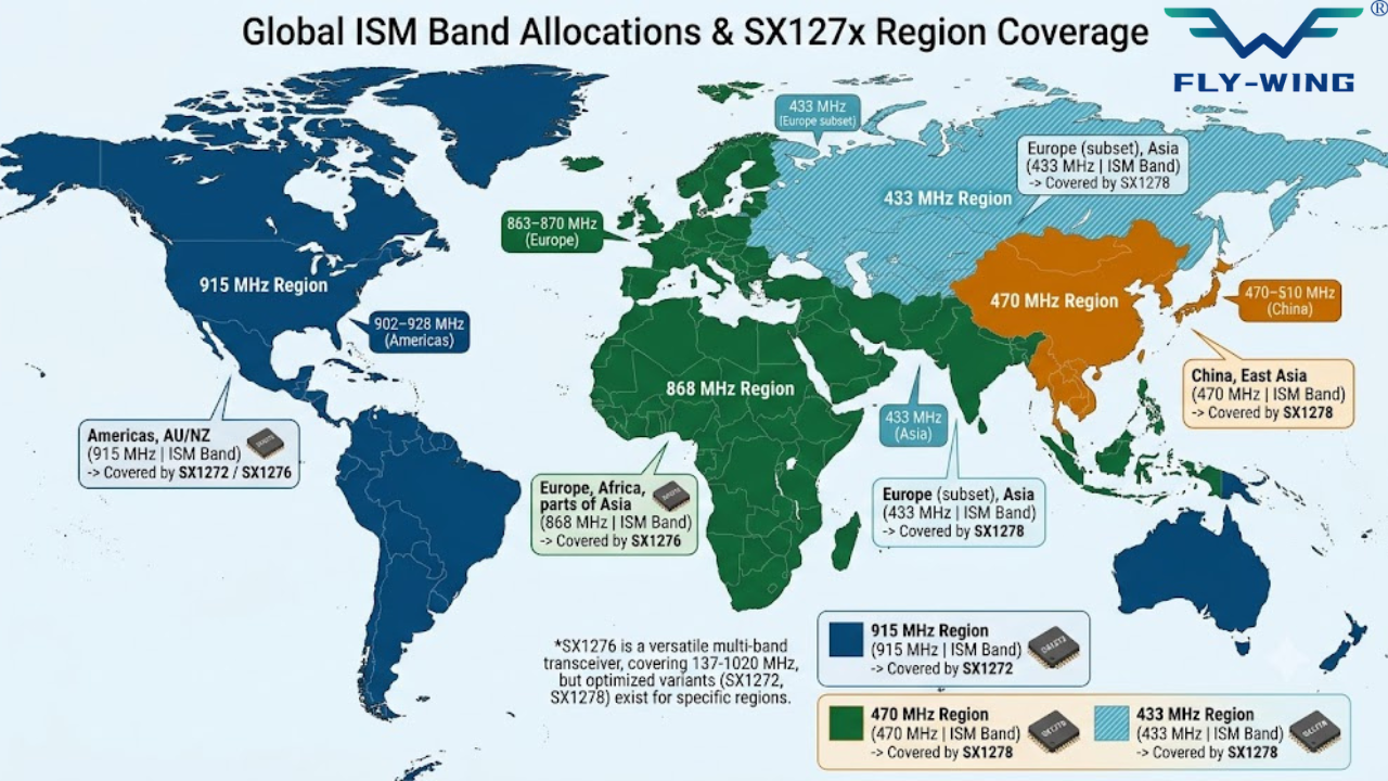
The SX1276 is capable of transmitting and receiving over a wide range of frequencies, starting at 137 MHz and extending through to 1020 MHz; therefore, this part number is suitable for all of the primary Sub-GHz ISM frequency allocations globally. The LoRa frequency is 868 MHz in Europe, 915 MHz in North America and Australia, and 433 MHz or 470-510 MHz in Asia (particularly China), with the additional use of the 169 MHz band for long-range machine-to-machine (M2M) applications in several regions around the globe.
The SX1276 and its companion devices can all work within these frequency ranges; however, not all of the family members can operate over these common ranges –SX1279 LoRa Transceiver operates over the 137-960 MHz range, whereas the SX1277/SX1278 are oriented more toward the lower frequency spectrum. In most cases, based on your designs, the SX1276 is likely to be your first choice for global access; however, if your engineering constraints increase your BOM costs to meet a particular country’s requirements, you can choose from one of the other family members.
Receiver Sensitivity: What −148 dBm Actually Means
Receiver sensitivity refers to the smallest amount of signal power the chipset can accurately read. The SX1276 decodes signals down to about −148 dBm or 0.016 femtowatts of RF energy.
This impressive sensitivity is the result of three key factors. First, the LoRa chirp spread spectrum technique provides a large processing gain (the energy from a signal gets spread across a much larger bandwidth and coherently de-spreads at the receiver). Second, the narrower bandwidths of the LoRa signals result in a much lower noise floor. Finally, Semtech has designed the low-noise amplifier in such a way that it maintains a tight noise figure.
In practical terms, a link that would be non-functional with FSK will typically function with LoRa using SF12. The SX1276 LoRa Transceiver can decode signals that are 20+ dB below the noise floor of the receiver. As a result, LoRa can achieve communication ranges that are difficult to match with conventional narrowband technologies.
SF12: −27.5 dB SNR threshold.
Both values represent the minimum SNR required to decode a packet with acceptable error rate. Higher spreading factors have more negative SNR thresholds, meaning they can decode signals buried deeper in noise. This is one of the key reasons LoRa achieves long-range performance.
Source: Semtech AN1200.13
TX Power Modes: PA_BOOST vs. RFO Path
The SX1276 LoRa Transceiver has two independent RF paths: one is for RFO mode (Radio Frequency output), and one is for PA_BOOST mode, which has a larger power output level than the RFO path due to a separate power amplifier being used.
The choice of RF path depends on how the module is designed. Many commercially available modules (like the popular RFM95W) will provide an antenna only through their PA_BOOST path, so if you configure your RFO register settings, you won’t get an RF output on these modules. Make sure to always review your module schematics before you configure any power settings in your application program.
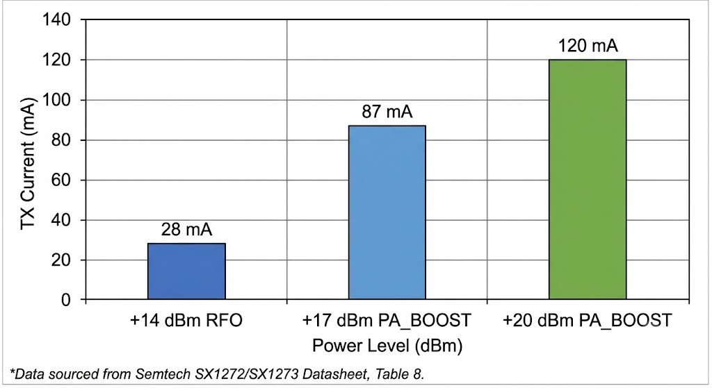
The current consumption is greatly affected by the transmit power (dBm). For example, at +20 dBm (PA_BOOST), the chip will consume approximately 120 mA while transmitting, while at +14 dBm (RFO), it will only consume about 28 mA. If you are using battery-operated sensors sending short packets and intervals, the overall current draw (average) is more important than just the maximum current draw (peak) for the purpose of determining your decoupling capacitor size/requirement; however, both factors impact the size of the decoupling capacitors as well.
Power States and Battery Life Math
The SX1276 LoRa Transceiver operates in four states: Sleep, Standby, RX (Continuous or Single), and TX. Understanding the current consumption in each state is essential for estimating battery life.
While in sleep mode, the chip draws less than 200nA (virtually nothing). The current for the chip in standby mode is about 1.6mA while running its crystal oscillator. Typically, the active RX (receiving) state will draw approximately 10.8mA, depending on selected features. TX current varies depending on the configured output power level, as described above.
To estimate battery life for a sensor transmitting one 50-byte packet every 15 minutes at SF9, +17 dBm: transmission time-on-air is about 370ms; at 87mA, this will add 0.00887mAh to your battery per packet. Four packets transmitted in a one-hour period will use 0.0355mAh/h from TX alone, resulting in an average usage of 0.00059mAh/min (for TX alone). The remaining 59.975 minutes will be added to your consumption at sleep current, which is essentially zero. Therefore, a 2000mAh battery will allow your sensor to transmit for just over three years. In practice, battery life is also limited by self-discharge and the power required during receive windows, rather than TX activity.
How LoRa Spread-Spectrum Modulation Works
LoRa is a proprietary implementation made by Semtech for chirp spread spectrum (CSS) modulation. It relies on the principle of spreading a signal across a large bandwidth in order to increase its resistance to interference from noise, which has been used in military communications since the 1940’s. The innovation of Semtech is to allow for this technology to be practically used at lower costs with low energy use compared to other existing solutions, enabling the development of low-cost IoT semiconductors.
Chirp Spread Spectrum: The Core Concept
A LoRa symbol is a chirp, a signal whose frequency sweeps continuously across the full channel bandwidth. An up-chirp starts at the lowest frequency in the band and sweeps to the highest. A down-chirp does the opposite. Data is encoded by starting the chirp at different frequency offsets within the band. Each possible starting offset represents a different symbol value.
At the receiver, a matched filter correlates the incoming signal against a reference chirp. Even if the signal is weaker than the noise floor, the coherent integration over the entire chirp duration builds up the signal while the noise averages out. This is the processing gain, and it scales with the spreading factor.
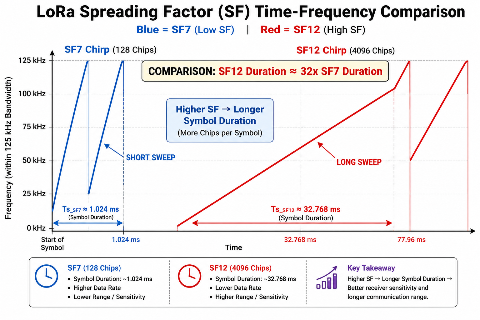
Spreading Factor (SF6 – SF12): The Most Important Parameter
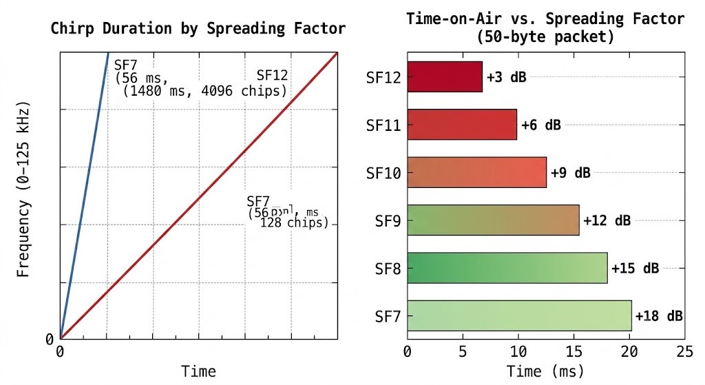
The spreading factor defines how many chips are used to represent a single symbol. In SF7, 1 symbol = 2^7 = 128 chips. In SF12, 1 symbol = 2^12 = 4096 chips. More chips per symbol result in longer transmission times. However, the trade-off of longer transmission times allows for a larger processing gain and improved sensitivity.
Every time you increase the spreading factor, the time on-air roughly doubles while the link budget increases by about 3 dB per step. For example, going from SF7 to SF12 increases the possible range by about 18 dB, but it also makes each packet approximately 32 times slower than before. Thus, this is the most significant design consideration for any LoRa deployment.
Most people do not understand that SF7 and SF8 are orthogonal; therefore, you can use both SF7 and SF8 at the same time in the same frequency channel without interference. This capability allows for a single gateway to decode multiple simultaneous transmissions with different spreading factors, one of the main reasons LoRaWAN networks are able to scale so well.
| SF | Chips/Symbol | Data Rate* (kbps) | ToA† (50B) | Link Gain (dB) |
|---|---|---|---|---|
| SF6 | 64 | ~9.4 | ~33 ms | Baseline |
| SF7 | 128 | ~5.5 | ~56 ms | +3 dB |
| SF8 | 256 | ~3.1 | ~103 ms | +6 dB |
| SF9 | 512 | ~1.8 | ~185 ms | +9 dB |
| SF10 | 1024 | ~1.0 | ~370 ms | +12 dB |
| SF11 | 2048 | ~0.54 | ~741 ms | +15 dB |
| SF12 | 4096 | ~0.29 | ~1.48 s | +18 dB |
Signal Bandwidth: Noise Floor vs. Data Rate
Signal bandwidth (BW) controls the width of the frequency sweep in each chirp. The SX1276 supports 10 bandwidth settings from 7.8 kHz up to 500 kHz. Narrowing the bandwidth has two effects: it lowers the noise floor (improving sensitivity by roughly 10*log10(BW1/BW2) dB), and it slows the data rate.
The standard deployment bandwidth is 125 kHz. This is what virtually all LoRaWAN configurations use. It gives a good balance of sensitivity and data rate, and most regional frequency plans are sized around it. Using 62.5 kHz halves the data rate but gains 3 dB of sensitivity. Using 500 kHz doubles the data rate but loses 6 dB.
Narrower bandwidths also increase sensitivity to frequency error between transmitter and receiver. Below 62.5 kHz, crystal tolerance becomes a serious concern. The SX1276 includes an automatic frequency correction (AFC) mechanism, but very narrow bandwidths require higher-quality crystals or TCXOs.
Coding Rate: Forward Error Correction
The SX1276 adds forward error correction (FEC) to LoRa transmissions via the coding rate parameter. Coding rates are expressed as 4/n, where n ranges from 5 to 8. A rate of 4/5 means 4 data bits per 5 transmitted bits, 20% redundancy overhead. A rate of 4/8 means 4 data bits per 8 transmitted bits, 100% redundancy.
Higher redundancy improves error correction at the cost of longer packets and more time-on-air. CR 4/5 is the standard for most deployments. CR 4/8 is useful in extremely noisy RF environments, near industrial machinery, in dense urban interference, or when the link is marginal and retransmissions must be minimized.
SX1276 Pinout, Package, and Hardware Integration
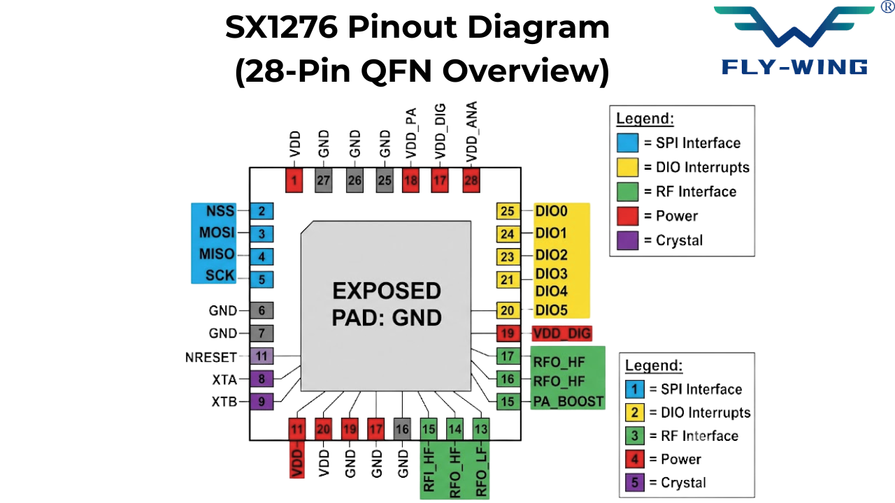
The 28-Pin QFN Package
An exposed thermal pad on the bottom of the SX1276 is housed in an exposed thermal pad QFN package type. The exposed thermal pad must be connected as an electrical ground and thermal ground. A chip’s performance will degrade if the thermal pad does not connect to ground because it is part of the RF ground reference and not just a mass for heat dissipation or a heat sink. QFN packages need to be designed carefully on the PCB. To ensure a good solder joint to the thermal pad, the solder stencil needs to provide enough solder paste for reflow and prevent bridging. Make the pad smaller than the exposed area, approximately at the size of the metal area, use 0.3mm via-in-pad or via-near-pad to connect to the internal ground plane.
SPI Interface and Register Access
Engineers perform all configuration and data transmission operations between the SX1276 and the host microcontroller via the SPI interface. The chip acts as a slave device when used with SPI. The chip supports two modes: Mode 0 and Mode 1. Engineers use Mode 0 more commonly in practice.The maximum frequency for SPI communication is 10 MHz during register access. The communication between MCU and SX1276 is done with one byte addressing of registers. During a write operation: bring NSS low, transmit the register address byte where bit 7 is high, transmit the data byte, bring NSS high. For read operation: bring NSS low, transmit the register address byte where bit 7 is zero, send dummy byte, and receive data byte, bring NSS high.
DIO Interrupt Lines (DIO0–DIO5)
The SX1276 has six digital input/output (I/O) pins that function as interrupt outputs. Their function will change based on both the operating mode (either LoRa or FSK) and the configuration of the mapping register. The most common mapping of the SX1276 digital I/Os in LoRa mode are as follows:
DIO0: TxDone (Transmission Complete) or RxDone (Reception Complete – This will be determined by the value set in RegDioMapping1[7:6])
DIO1: RxTimeout or FhssChangeChannel
DIO2: FhssChangeChannel or Unused
DIO3: CadDone (Channel Activity Detection Complete)
DIO4: CadDetected or PllLock
DIO5: ModeReady or ClkOut
For minimal implementations, DIO0 should be connected to an MCU interrupt pin. After starting transmission, poll the TxDone flag in a loop, or configure DIO0 to generate an interrupt on the rising edge of the signal. In receive mode, configure DIO0 to be RxDone and listen for the interrupt.
Antenna Selection and Matching
The SX1276 uses RF output pins (RFO_LF, RFO_HF, and PA_BOOST) that interface with a 50-ohm transmission line. Engineers design a matching network between the IC and the antenna connector to minimize reflected power and maximize antenna efficiency.
For PA_BOOST operation at 868 MHz and 915 MHz, the matching network typically uses a π (pi) configuration consisting of series capacitors and shunt inductors. However, the exact component values depend on PCB trace parasitics, connector effects, and overall layout. Semtech reference designs provide starting values, but engineers must perform final tuning in the lab using a vector network analyzer (VNA) or return loss measurements.
Engineers commonly choose a quarter-wave whip antenna tuned for the target frequency band. At 868 MHz, a quarter-wave antenna is approximately 86 mm long, while at 915 MHz it is about 82 mm.
For compact designs, engineers use PCB-integrated antennas such as meandered monopoles or chip antennas. These reduce size but introduce higher losses compared to external antennas with proper ground planes, resulting in reduced range.
SX1276 Register Configuration: Initializing LoRa Mode
The bring-up sequence for the SX1276 follows a specific order. Some mode changes are only valid from certain operating states. Getting the sequence wrong produces no error; the chip simply ignores the command. This is a common source of confusion during the first bring-up.
| Register Name | Address | Key Bits | Function |
|---|---|---|---|
| RegOpMode | 0x01 | Bits [2:0] & Bit 7 | Set operating mode; Bit 7 = LoRa mode selector |
| RegFrfMsb/Mid/Lsb | 0x06–0x08 | All bits | 24-bit frequency word: Frf = Fc / Fstep (Fstep ≈ 61.04 Hz) |
| RegPaConfig | 0x09 | Bits [7:4] | PA_BOOST enable (bit 7), MaxPower, OutputPower fields |
| RegModemConfig1 | 0x1D | Bits [7:4] & [3:1] | Bandwidth (BW) and Coding Rate (CR) selection |
| RegModemConfig2 | 0x1E | Bits [7:4] | Spreading Factor (SF) setting; bits [7:4] |
| RegModemConfig3 | 0x26 | Bit 3 | Low data rate optimization — enable for SF11/SF12 at BW 125 kHz |
| RegPreambleMsb/Lsb | 0x20–0x21 | All bits | Preamble symbol length; minimum 6 symbols recommended |
| RegPayloadLength | 0x22 | All bits | Payload byte count in implicit header mode |
| RegFifoTxBaseAddr | 0x0E | All bits | FIFO TX buffer base address (default 0x00) |
| RegFifoRxBaseAddr | 0x0F | All bits | FIFO RX buffer base address (default 0x00) |
Step 1: Enter Sleep Mode
Before switching from FSK to LoRa mode, the chip must be in the sleep state. In any other state, writing Bit 7 of RegOpMode is ignored. Write 0x00 to RegOpMode (Sleep mode, FSK). Verify the write by reading back the register.
Step 2: Enable LoRa Mode
With the chip in Sleep, write 0x80 to RegOpMode. This sets Bit 7 high, which selects the LoRa modem. The lower 3 bits remain 000 Sleep mode. The chip is now in LoRa Sleep. All subsequent LoRa register addresses are now valid.
Step 3: Set Carrier Frequency
Engineers set the frequency using a 24-bit register word that they split across RegFrfMsb (0x06), RegFrfMid (0x07), and RegFrfLsb (0x08). The formula is: Frf = Fc / Fstep, where Fstep = FXOSC / 2^19 ≈ 61.035 Hz for a 32 MHz crystal.
Example for 915.0 MHz: Frf = 915,000,000 / 61.035 = 14,991,360 = 0xE4C000. Write 0xE4 to RegFrfMsb, 0xC0 to RegFrfMid, 0x00 to RegFrfLsb. For 868.0 MHz: Frf ≈ 0xD90000. Always compute from your exact crystal frequency rather than using approximations.
Step 4: Configure Modem Parameters
RegModemConfig1 (0x1D) holds bandwidth and coding rate. Bits [7:4] set BW: 0111 = 125 kHz, 1000 = 250 kHz, 1001 = 500 kHz. Bits [3:1] set CR: 001 = 4/5, 010 = 4/6, 011 = 4/7, 100 = 4/8. Bit 0 enables implicit header mode.
RegModemConfig2 (0x1E) holds the spreading factor in bits [7:4]: SF7 = 0x70, SF9 = 0x90, SF12 = 0xC0. Bit 2 enables CRC. Engineers set Bit 3 in RegModemConfig3 (0x26) when they use SF11 or SF12 with 125 kHz bandwidth. This setting enables low data rate optimization, which ensures correct symbol timing at these configurations.
Step 5: Configure TX Power
Write RegPaConfig (0x09). If using PA_BOOST: set Bit 7 = 1, set MaxPower (bits [6:4]) = 7 (maximum), and set OutputPower (bits [3:0]) = Pout − 2. For +20 dBm, OutputPower = 0xF (15), giving 17 + 15 − 15 = 17… at standard setting. To reach +20 dBm, additionally write 0x87 to RegPaDac (0x4D) to enable the high-power mode.
If using RFO path (non-PA_BOOST modules): Bit 7 = 0, MaxPower sets the ceiling. Output power = −4 + MaxPower + OutputPower / 10.4 dBm. Never set PA_BOOST if your module routes to the RFO antenna path — you will transmit nothing and wonder why.
Step 6: Transmit a Packet
Set RegFifoTxBaseAddr (0x0E) = 0x00. Set RegFifoAddrPtr (0x0D) = 0x00. Write payload bytes to the FIFO register (0x00) via SPI. Set RegPayloadLength (0x22) to the number of bytes written. Move the chip to TX mode: write 0x83 to RegOpMode. Wait for DIO0 to assert (TxDone interrupt) or poll RegIrqFlags (0x12) bit 3. Clear the interrupt by writing 0xFF to RegIrqFlags.
SX1276 Application Domains
Wireless Sensor Networks and Agricultural IoT
Agricultural deployments present some of the most demanding conditions for wireless sensors. Fields are large, often measured in hectares. Infrastructure is sparse. Batteries must last seasons. And signals must pass through crops, terrain undulations, and wooden/metal structures.
SX1276-based nodes are well suited to these conditions. A typical deployment uses SF9 or SF10 at 125 kHz bandwidth. This provides a link budget of approximately 157–160 dB after accounting for real-world losses. At this budget, even heavily obstructed paths of 3–5 km are achievable. Soil moisture sensors, weather stations, irrigation valve controllers, and livestock trackers all appear in deployed LoRa agricultural networks.
Node density management requires careful SF assignment. Assign SF7 to nodes close to the gateway — this minimizes their time-on-air, freeing channel capacity. Assign higher SFs to edge nodes that need the extra link margin. This approach is codified in LoRaWAN’s Adaptive Data Rate (ADR) mechanism.
Automated Meter Reading (AMR)
Utility metering, electricity, gas, water was one of the first mass deployments of LoRa technology. Meters report consumption at scheduled intervals: typically once per hour or once per day. Packet sizes are small (20–50 bytes). Network coverage must span entire cities.
For AMR, duty cycle compliance is critical. In Europe, ETSI EN 300 220 mandates a maximum 1% duty cycle in the 868 MHz band (sub-band dependent). At SF9 and 125 kHz bandwidth, a 50-byte packet takes approximately 185 ms. One packet per hour gives a duty cycle of 185 / 3,600,000 = 0.005%, well within limits. This leaves substantial headroom for retransmissions and acknowledgments.
Industrial Remote Monitoring: Link Budget Worked Example
For an industrial non-line-of-sight (NLOS) deployment — a pump station 4 km from a LoRaWAN gateway, with two concrete walls and some terrain between them — consider the following link budget:
- TX power: +20 dBm (PA_BOOST, SX1276)
- TX antenna gain: +2 dBi (short fiberglass whip on enclosure)
- Cable / connector loss at TX: −0.5 dB
- Free-space path loss at 868 MHz over 4 km: approximately −133 dB
- Obstacle penetration loss (2 × concrete walls): −15 dB (estimated 7.5 dB each)
- RX antenna gain (gateway, 6 dBi directional): +6 dBi
- Cable / connector loss at RX: −1 dB
- Received signal level: 20 + 2 − 0.5 − 133 − 15 + 6 − 1 = −121.5 dBm
- SX1276 sensitivity at SF10 (125 kHz): approximately −145 dBm
- Link margin: −121.5 − (−145) = +23.5 dB margin — link viable
A 23 dB margin is comfortable. You could add another 15 dB of obstructions before the link fails. This illustrates why industries use LoRa in harsh environments where other radio technologies would require repeaters.
Regional Regulatory Constraint
Selecting the SX1276 for a product requires understanding the regulations governing its operating frequency. Three major regulatory regimes cover most commercial deployments:
- Europe (ETSI EN 300 220, 868 MHz band): Maximum EIRP +14 dBm in most 868 MHz sub-bands. Duty cycle limits: 0.1–1% depending on sub-band. Some sub-bands allow up to +27 dBm under Listen Before Talk (LBT) with channel access protocol.’’
- United States (FCC Part 15, 902–928 MHz): Maximum EIRP +30 dBm. No duty cycle limit, but frequency hopping or direct sequence spread spectrum required if power exceeds +1 dBm. LoRa’s CSS modulation qualifies as spread spectrum.
- India (WPC/DoT, 865–867 MHz): Maximum EIRP +1 W (30 dBm). Channels defined at 865.0625–866.975 MHz. No duty cycle limit currently mandated but LoRaWAN Alliance guidelines recommend adhering to 1%.
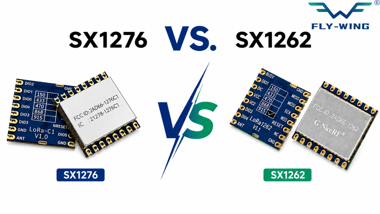
SX1276 vs. SX1262: An Engineering Trade-off, Not an Upgrade
The SX1262 is Semtech’s second-generation LoRa transceiver. It launched in 2019. The marketing materials position it as a replacement for the SX127x family. The engineering reality is more nuanced. Whether to migrate depends on what matters in your specific design.
Specification Comparison
| Parameter | SX1276 | SX1262 |
|---|---|---|
| Generation | 1st gen (2013) | 2nd gen (2019) |
| Sensitivity (LoRa) | −148 dBm | −148 dBm |
| Max TX Power | +20 dBm | +22 dBm |
| RX Current | ~10.8 mA | ~4.6 mA |
| Sleep Current | < 200 nA | < 900 nA |
| Frequency Range | 137–1020 MHz | 150–960 MHz |
| Spreading Factor | SF6 – SF12 | SF5 – SF12 |
| Max Data Rate | ~37.5 kbps | ~62.5 kbps |
| Package | 28-pin QFN | 24-pin QFN |
| Library Support | Very mature | Growing (RadioLib) |
| Best For | Cost, existing PCBs | New battery designs |
7.2 Battery Life Impact
The greatest strength of SX1262 is its RX current – 4.6 mA compared to the SX1276’s 10.8 mA. This improves RX power by 2.3 times in Class C LoRaWAN devices because they operate continuously. However, it provides fewer benefits for Class A LoRaWAN devices, where the receiver only activates briefly after transmission. As an example, a device that transmits 1 packet every hour using SF9 at +17 dBm, having 2 RX windows after each TX. Using a 2000 mAh cell, a node powered by SX1276 would operate for around 544 days. The same node, but powered by SX1262, would last approximately 952 days or 75% more – enough to skip one battery change within a 5-year lifecycle of a product.
When to Keep SX1276
The SX1276 is not discontinued. It remains in production. Several practical reasons support staying with it for new designs:
- Existing certified hardware. If you have CE, FCC, or IC-certified modules based on SX1276 (RFM95W, Ra-01H), re-certification after migrating to SX1262 modules requires new testing. This costs time and money.
- Library maturity. RadioHead, LoRaLib/RadioLib, LMIC, and Arduino-LoRa all have years of SX1276 testing and edge-case fixes. SX1262 support in some libraries is newer and occasionally has rough edges.
- Cost. In some supply chains, SX1276-based modules are cheaper than SX1262 equivalents. For cost-sensitive, high-volume applications not constrained by battery life, the older chip can be the better choice.
- 433 MHz designs. Many 433 MHz applications still use SX1276. Some SX1262 module variants exist at 433 MHz but are less common.
Code Migration Path
Although the SX1276 and SX1262 share similar product characteristics, they use completely different register maps. As a result, code written for one chip cannot run on the other without modification to match the respective registers.
The RadioLib library, developed by Jan Gromes, supports both chips and provides nearly identical API calls. Developers should use this library to create a single abstraction layer for working with both devices. The SX1262 also has a large difference in physical size compared to the SX1276.
Manufacturers offer the SX1262 in a 24-pin QFN (LQFP) package, while they provide the SX1276 in a 28-pin LQFP package. As such, the two devices are not pin-compatible, and when changing from one part number to another, a complete redesign of your PCB will be necessary if you are migrating from bare chip to bare chip. If you are migrating from module to module (i.e., RFM95W to Ra-02), you will need to check that both your antenna connector location and SPI pin mapping match on your carrier board.
Popular SX1276-Based Modules
RFM95W (HopeRF)
The RFM95W is a castellated SMD module widely used in prototyping and production hardware. It integrates the SX1276 with a matching network, crystal, and antenna trace all on a 16 × 17 mm board. The W suffix denotes the wideband variant (137–1020 MHz). The HF (high-frequency) variant targets 868/915 MHz specifically.
Important: the RFM95W routes to the PA_BOOST pin only. Your code must configure the PA_BOOST path or produce no RF output. The module includes an SMA footprint on some versions; others use a U.FL connector. Verify before ordering for production. It carries no regulatory certification on its own — final product certification is the product manufacturer's responsibility.
Ra-01 / Ra-01H (Ai-Thinker)
The Ra-01 operates in the 433 MHz frequency range using an SX1278 chip, while the Ra-01H operates at 470 MHz via an SX1276 chip. They are both stamp-hole-type modules with U.FL antenna connections and exposed SPI pads. They are popular low-cost options for deployments in Asian markets where 433/470 MHz licensing is more favorable than more regulated markets. Engineers in India extensively use the Ra-01H for IoT applications on the IN865 band. Users have reported RF noise problems in a few batches of the Ra-01H; therefore, if you experience poor range, use a spectrum analyzer to confirm that RF noise is not the cause. You should supply the module with a 3.3 V logic level; if your MCU outputs 5 V, use an LDO regulator from the 5 V source to power the module.
EBYTE E32 Series
EBYTE offers an alternative design through their E32 modules by providing a UART-transparent protocol instead of providing SPI access directly. Therefore, the user can easily integrate any MCU equipped with a UART interface (e.g., a legacy 8-bit microcontroller) into E32 modules. Typical E32 modules include the E32-915 T30D (15 dBm version) and the E32-868 T20D (30 dBm version). These modules use different configurations for channel, address, and air rate, which engineers can set through the CONFIG serial port using three AT commands. When an application needs only a long-range transparent serial connection and does not require direct access to the LoRaWAN stack, the E32 modules provide the quickest method to implement this type of connection.
Frequently Asked Questions
Under ideal line-of-sight conditions, SX1276 can reach 15 km+. In real urban environments, the typical range is 2–5 km depending on the antenna, TX power, and spreading factor.
Use SF7 for short range/high data rate. SF9–SF10 for balanced performance. SF12 only for maximum range, but it significantly increases time-on-air.
No. SX1276 is only the RF transceiver. LoRaWAN runs on a microcontroller using a software stack like LMIC or Arduino LoRaWAN.
They are similar chips with different frequency support. SX1276 is the most commonly used for 868/915 MHz global designs.
No. It works at 3.3V and is not 5V tolerant. A level shifter is required for SPI lines when using 5V MCUs.
Yes, for cost-sensitive and proven designs. However, newer chips like SX1262 offer lower power consumption and better performance for new products.
Conclusion
The SX1276 LoRa Transceiver (including SX1278 variants) is a proven low-power, long-range wireless solution designed for reliable IoT communication. With its strong link budget, high receiver sensitivity, and flexible LoRa modulation settings, it delivers consistent performance even in challenging environments. Therefore, it is widely used in smart agriculture, industrial monitoring, asset tracking, and remote sensing applications.
Although newer transceivers such as the SX1262 LoRa Transceiver offer better power efficiency and improved battery life, the SX1276 still remains highly relevant. This is mainly due to its mature ecosystem, extensive library support, and ease of integration in both prototype and production systems.
In conclusion, the SX1276 is still a reliable, cost-effective, and well-established choice for long-range IoT communication, especially where stability and proven performance are more important than adopting the newest hardware.
COMMENTS