When a circuit needs high capacitance in a compact package, an electrolytic capacitor is often the practical choice.
Electrolytic capacitors are used for DC power supply smoothing, ripple filtering, audio coupling, and bulk energy storage.
They can provide capacitance values in the hundreds or thousands of microfarads at a reasonable cost, which makes them useful in consumer electronics, industrial control systems, motor drives, LED drivers, and power conversion equipment.
This guide explains what an electrolytic capacitor is, how it works, its main types, polarity markings, electrical ratings, failure modes, and how to select the right part for your circuit.
What Is an Electrolytic Capacitor?
An electrolytic capacitor is a polarized capacitor that uses an electrochemically formed oxide layer as its dielectric.
This structure gives it much higher capacitance than most ceramic or film capacitors of a similar size. Because of this, electrolytic capacitors are commonly used where high capacitance and low cost matter more than non-polarized operation.
The defining characteristics of an electrolytic capacitor are:
- It stores charge across a thin oxide dielectric.
- It has a positive terminal, called the anode.
- It has a negative terminal, called the cathode.
- It must be connected with the correct polarity in most DC circuits.
- It is available in values from under 1µF to tens of thousands of µF.
- It has a limited operating life because the electrolyte ages over time.
Why Is It Called an Electrolytic Capacitor?
The name comes from the electrolyte inside the component. Unlike a basic capacitor where both electrodes are solid metal, an electrolytic capacitor uses a liquid, gel, or solid electrolyte as part of the cathode system.
The electrolyte makes close contact with the rough, oxidized surface of the anode foil. T
his allows the capacitor to use the full microscopic surface area of the etched foil, which is one reason electrolytic capacitors can achieve high capacitance in a compact body.
In some aluminum electrolytic capacitors, the electrolyte can also help reform small defects in the oxide layer during normal operation.
However, this effect has limits and cannot protect the capacitor from major overvoltage, reverse polarity, or overheating.
How Does an Electrolytic Capacitor Work?
The construction of an electrolytic capacitor begins with the anode.
In an aluminum electrolytic capacitor, manufacturers etch high-purity aluminum foil to increase its surface area. They then anodize the foil to form a thin layer of aluminum oxide (Al₂O₃).
This oxide layer acts as the dielectric.
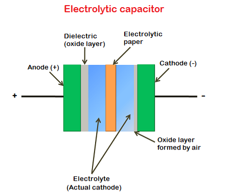
A paper separator soaked in liquid electrolyte is then placed against the oxide surface. A second aluminum foil acts as the cathode terminal.
Both foils and the separator are wound into a cylinder and sealed in an aluminum can.
The oxide layer is extremely thin, and the etched aluminum foil has a much larger surface area than a flat foil.
Together, these features allow the capacitor to store a large amount of charge in a small package, giving it much higher capacitance than many other capacitor types.
Electrolytic Capacitor Dielectric and Electrolyte
The dielectric is the aluminum oxide layer. It is thin, hard, and electrically insulating. Its thickness affects the voltage rating. A thicker oxide layer can support a higher voltage, but it also reduces capacitance per unit area.
The electrolyte is a separate functional material. It is not the dielectric. Its role is to form part of the internal cathode system and maintain electrical contact with the oxide-coated anode surface.
The electrolyte affects several important capacitor properties, including:
- ESR
- leakage current
- ripple current handling
- operating temperature
- service life
In wet aluminum electrolytic capacitors, electrolyte dry-out is one of the main aging mechanisms.
As temperature and ripple current stress increase, the electrolyte gradually degrades or evaporates through the seal. This raises ESR, reduces capacitance, and eventually causes failure.
Electrolytic capacitor dielectric absorption is a secondary effect. After the capacitor discharges, a small residual voltage can reappear across the terminals. This usually does not matter in power filtering, but it can matter in precision timing and analog circuits.
Main Types of Electrolytic Capacitors
Electrolytic capacitors are available in several types. Each type uses a different anode material or electrolyte system. The right choice depends on voltage rating, capacitance, ESR, size, stability, cost, and reliability.
Aluminum Electrolytic Capacitor
The aluminum electrolytic capacitor is by far the most widely used type.
Also written as aluminium electrolytic capacitor or al electrolytic capacitor, it covers capacitance values from around 0.1 µF to tens of thousands of µF at voltages from a few volts to over 500 V.
Available in radial, axial, snap-in, screw-terminal, and SMD packages, the electrolytic aluminum capacitor is the standard choice for DC bus smoothing, power supply filtering, audio coupling, and bulk energy storage in industrial electronics.
Flywing Tech stocks over 150,000 listings of aluminum electrolytic capacitors from leading manufacturers including Nichicon, Panasonic, United Chemi-Con, Rubycon, Vishay, and EPCOS, covering standard and low-ESR grades across all common package types.
Tantalum Electrolytic Capacitor
Tantalum electrolytic capacitors use a sintered tantalum body as the anode, tantalum pentoxide as the dielectric, and manganese dioxide or conductive polymer as the cathode layer.
They offer stable capacitance over temperature and time. They also provide high capacitance in a compact footprint.
However, tantalum capacitors cost more than aluminum electrolytic capacitors and usually have a lower maximum voltage range. They are also sensitive to voltage surges, inrush current, and reverse polarity.
When users compare tantalum vs electrolytic capacitors, they usually mean tantalum vs aluminum electrolytic capacitors. Tantalum is technically part of the electrolytic capacitor family.
Use tantalum capacitors where compact size and stable capacitance matter. Use aluminum electrolytic capacitors where bulk capacitance, high voltage, and cost are more important.
Voltage derating is essential in tantalum designs. Flywing Tech’s tantalum capacitor catalog includes both MnO₂ and polymer variants across standard SMD case sizes.
Polymer Electrolytic Capacitor
Polymer electrolytic capacitors use a conductive polymer instead of a liquid electrolyte.
This gives them lower ESR, better ripple current handling, and improved thermal stability compared with many wet aluminum electrolytic capacitors.
Since they do not rely on liquid electrolyte in the same way, they are less affected by dry-out.
Polymer electrolytic capacitors are common in:
- switching power supplies
- motherboard power stages
- low-voltage regulator outputs
- compact power circuits
- high-ripple applications
Their main limits are cost and voltage range. Many polymer electrolytic capacitors are designed for low-voltage applications.
For example, Panasonic aluminum-polymer capacitors such as the 72SXE82M, 16SVPG820M, 100SXV39M, and 80SXV82M show how polymer capacitor families cover different capacitance, voltage, and package needs.
Non-Polarized / Bipolar Electrolytic Capacitor
A non-polarized electrolytic capacitor, also called a bipolar electrolytic capacitor, can handle voltage that changes direction.
It is often made using two polarized capacitor structures connected back-to-back. This reduces capacitance density, but it allows the capacitor to work in AC signal paths.
Common applications include:
- speaker crossover networks
- audio equalization circuits
- AC coupling paths
- circuits where voltage polarity can reverse
Do not replace a bipolar electrolytic capacitor with a standard polarized electrolytic capacitor unless the circuit specifically allows it.
Electrolytic Capacitor Symbol and Polarity
Before fitting an electrolytic capacitor into a circuit, two things must be clear: the schematic symbol and the terminal polarity. A mistake in either one can cause poor circuit performance, overheating, leakage, venting, or complete capacitor failure.
Electrolytic Capacitor Symbol in Schematics
In schematic diagrams, the electrolytic capacitor symbol is a modified version of the standard capacitor symbol with a polarity indicator.
One common convention uses a curved line for the negative plate and a straight line for the positive plate, with a + sign adjacent to the positive terminal.
Another convention uses two parallel lines with a + marker and a filled arc on the cathode side.
The exact schematic symbol for an electrolytic capacitor varies slightly between standards. IEEE, IEC, and JIS notation differ in some details, but the + marker on the positive terminal is consistent.
The electrolytic capacitor circuit symbol is always distinguishable from a non-polarized capacitor by this polarity indicator.
On PCB silkscreen, the positive terminal is typically indicated by a + or a longer lead marker, while the negative side is shown as a shaded or striped area on the component body outline.
Electrolytic Capacitor Polarity: Positive and Negative Terminals
Correct polarity is non-negotiable for polarized electrolytic capacitors. Reversing the terminals applies voltage in the wrong direction across the oxide dielectric, causing it to break down.
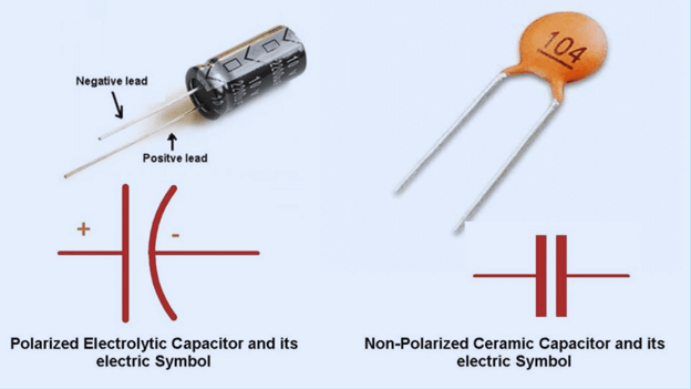
The result is a rapid rise in leakage current, internal overheating, electrolyte vaporization, and, in severe cases, venting or rupture.
On leaded radial aluminum electrolytic capacitors, the negative lead is shorter and the capacitor body carries a printed stripe along the negative side.
On SMD electrolytic capacitors, polarity marking varies by manufacturer but typically uses a stripe, dot, or notch on the negative side.
Always confirm the datasheet for any unfamiliar component. For a broader look at how polarity and decoupling interact in circuit design, see the decoupling capacitor placement guide on the Flywing Tech blog.
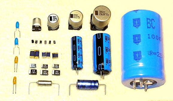
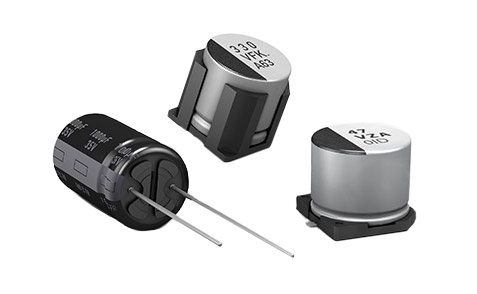
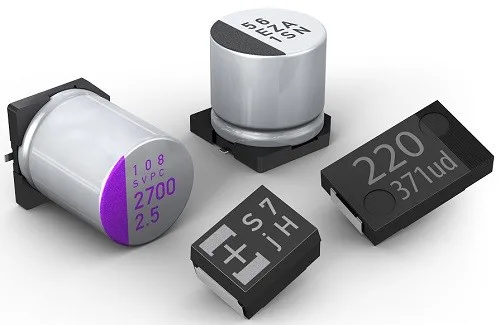
Common Electrolytic Capacitor Packages
Electrolytic capacitors come in several physical formats, and the package determines how the component mounts to a board, how it is handled in assembly, and what footprint the PCB layout must accommodate.
The three formats you will encounter most often are radial, axial, and SMD, each suited to different assembly processes and space constraints.
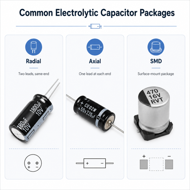
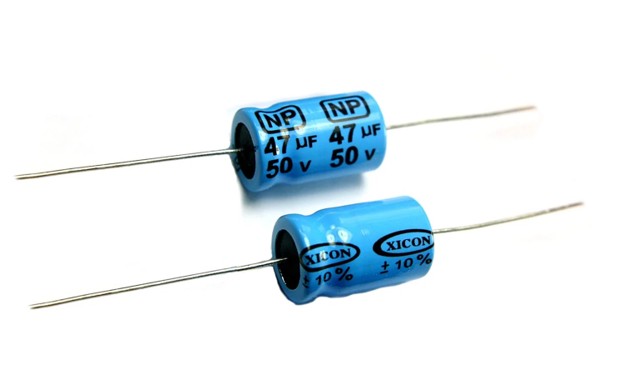
Radial Electrolytic Capacitor
In a radial electrolytic capacitor, both leads exit from the same end of the cylindrical body. This is the most common package for through-hole PCB assembly.
Radial electrolytic capacitors cover the widest range of capacitance and voltage values and are the default choice for most general-purpose through-hole designs.
Axial Electrolytic Capacitor
An axial electrolytic capacitor has one lead at each end of the cylindrical can.
This package was common in older electronics and audio equipment and remains useful for chassis-mount and vintage repair work where the component must lie flat on the board or be mounted between two points in a tube layout.
SMD Electrolytic Capacitor
SMD electrolytic capacitors are cylindrical aluminum electrolytic capacitors in surface-mount format, delivered in tape and reel.
Common body sizes range from 4 mm to 10 mm in diameter. Polarity is marked on the body with a stripe indicating the negative terminal.
For engineers working in KiCad or similar EDA tools, SMD electrolytic capacitor footprints are sized to match the physical body.
A commonly used example is the 4×5.4 mm footprint for compact 16V 1000µF SMD and 25V 1000µF SMD electrolytic capacitors.
Part libraries such as SnapMagic and LCSC provide ready-made KiCad models for these footprints that match standard part dimensions.
Key Electrical Ratings and Specifications
A capacitance value printed on the body is only the starting point. Electrolytic capacitors carry several ratings that directly affect whether a part performs reliably or fails early in its application.
Understanding each one before selecting a component saves troubleshooting time and prevents costly field failures.
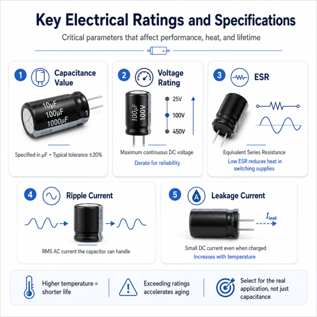
Capacitance Value
Electrolytic capacitors are specified in microfarads (µF). Common values in general electronics range from 1 µF to 10,000 µF.
A 10µF electrolytic capacitor works well for local supply bypassing. A 100µF capacitor can filter the output of small linear regulators.
A 1000µF capacitor is common on the low-voltage output side of AC-DC power supplies. Large bus capacitors, such as 12000µF 63V aluminum electrolytic capacitors, appear in motor drives and audio power stages.
Tolerance on electrolytic capacitors is typically ±20%, so measured capacitance can vary noticeably from the marked value.
Voltage Rating and Breakdown Voltage
The voltage rating is the maximum DC voltage that can be continuously applied across the capacitor. Exceeding it degrades the oxide dielectric and shortens operating life.
In high-reliability designs, capacitors are typically derated to 70–80% of their rated voltage to provide margin against transients.
The breakdown voltage in electrolytic capacitors is the point at which the dielectric fails catastrophically, substantially above the rated working voltage but not a safe operating point under any circumstances.
For applications on mains-connected circuits, motor drives, and inverters, high voltage electrolytic capacitors rated at 250 V, 350 V, or 450 V are required.
For general use cases such as 100V electrolytic capacitors in industrial control boards, always confirm voltage headroom against peak supply conditions.
ESR: Equivalent Series Resistance
ESR is one of the most critical specifications for electrolytic capacitors in switching power supplies and DC-DC converters.
It represents the resistive impedance of the capacitor at a given frequency. High ESR causes internal power dissipation during ripple current flow, generating heat that accelerates electrolyte aging.
Low ESR electrolytic capacitors use higher-conductivity electrolytes and optimized foil geometry to achieve ESR values significantly below general-purpose types.
In switching regulator output stages, always specify low ESR electrolytic capacitors unless the application explicitly permits a standard type.
Ripple Current Rating
Ripple current is the RMS value of the AC component flowing through the capacitor, typically at the switching frequency of the power supply.
The ripple current rating is the maximum RMS AC current the capacitor can handle continuously without exceeding its internal thermal limits.
Exceeding this rating raises internal temperature, accelerates aging, and shortens life.
Leakage Current
All electrolytic capacitors pass a small DC current even when fully charged. At normal operating conditions this is not a sign of failure; it is a characteristic of the oxide dielectric.
Aluminum electrolytic capacitor leakage current roughly doubles every 10°C rise in operating temperature.
This is one of the primary reasons operating temperature management matters so much for long-term reliability.
Electrolytic Capacitor Applications
Electrolytic capacitors serve several core roles across electronic systems. Their high capacitance makes them useful for filtering, smoothing, energy storage, and signal coupling.
Power Supply Filtering and DC Bus Smoothing
Power supply filtering is one of the most common electrolytic capacitor applications. After rectification, the DC output still contains AC ripple.
A large electrolytic capacitor across the supply rail charges toward the peak voltage and discharges into the load between peaks.
As a result, it reduces ripple and helps maintain a steadier DC voltage. The full bridge rectifier guide on the Flywing Tech blog covers how filter capacitor sizing works in rectified power supplies.
Audio Coupling and Decoupling
Electrolytic capacitors are also common in audio circuits. They can block DC while allowing audio-frequency AC signals to pass between amplifier stages.
They also appear across amplifier supply pins to reduce ripple and improve stability. The LM386 audio amplifier guide shows specific electrolytic values used for supply bypassing and gain adjustment.
LED Drivers and Power Conditioning
LED drivers often use electrolytic capacitors for output smoothing and ripple reduction. They help maintain a more stable current or voltage at the LED load.
Industrial control boards also use electrolytic capacitors for local power conditioning, especially where regulators, relays, sensors, and communication circuits share the same supply rail.
Motor Drives, UPS Systems, and Inverters
Motor drives, UPS systems, and inverters use electrolytic capacitors for bulk energy storage. These capacitors help support the DC bus during sudden load changes.
They also reduce voltage dips when motors start, switches change state, or high-current loads activate.
Speaker Crossover Networks
Bipolar electrolytic capacitors are often used in speaker crossover networks. Unlike standard polarized electrolytic capacitors, bipolar types can handle AC signals where the voltage reverses direction.
This makes them suitable for audio paths where a normal polarized electrolytic capacitor would not be appropriate.
For passive component selection principles more broadly, the passive electronic components guide provides useful context on where each component type belongs in a circuit.
Applications of Large Electrolytic Capacitors
Large electrolytic capacitors in the range of 10,000 µF to 44,000 µF at voltages of 25 V to 100 V appear in audio power amplifiers, DC motor drives, and UPS systems.
A 44000µF 25V electrolytic capacitor is usually used for bulk energy storage. It supplies peak current during sudden load spikes and helps stop the supply voltage from dropping when a heavy load turns on.
Ceramic Capacitor vs Electrolytic Capacitor
Both ceramic and electrolytic capacitors store electrical energy, but they suit fundamentally different circuit roles.
| Feature | Electrolytic Capacitor | Ceramic Capacitor |
| Capacitance range | High: 1 µF to 10,000 µF+ | Low to medium: 1 pF to ~100 µF |
| Polarity | Usually polarized | Non-polarized |
| Size | Larger for the same capacitance | Smaller |
| ESR | Usually higher | Usually lower |
| Frequency performance | Better at low frequency | Better at high frequency |
| Best use | Power filtering, bulk storage, audio coupling | High-frequency bypass, decoupling, signal filtering |
| Cost at high capacitance | Cost-effective | Expensive or impractical |
The practical conclusion: use electrolytic capacitors when high capacitance at low to moderate frequency is needed.
Use ceramic capacitors for small values, high-frequency bypass, and non-polarized applications.
Many designs use both: electrolytic for bulk supply storage, ceramic MLCCs for local decoupling at each IC supply pin.
For a thorough look at ceramic capacitor types and behavior, see the ceramic capacitor types overview and the MLCC guide on the Flywing Tech blog.
Tantalum vs Electrolytic Capacitor
Tantalum capacitors are technically a subcategory of electrolytic capacitors, but comparing tantalum vs electrolytic in practice almost always means comparing tantalum against aluminum electrolytic types.
For a full comparison with ceramic alternatives, see the tantalum capacitors vs ceramic guide.
| Property | Aluminum Electrolytic | Tantalum Electrolytic |
| Size | Larger | More compact |
| Capacitance stability | Moderate | Better over temperature |
| Cost | Lower | Higher |
| Voltage range | Up to 500 V+ | Typically below 50 V |
| Failure mode | Usually opens | Can short-circuit |
| Surge tolerance | Reasonable | Low; requires derating |
| Typical application | Bulk filtering, audio, industrial | Compact portable electronics, medical, precision analog |
Choose tantalum where compact size, stable capacitance, and long service life outweigh cost. Choose aluminum electrolytic where bulk capacitance, higher voltage, or unit cost is the driving factor.
Electrolytic Capacitor Failure Modes
Understanding how electrolytic capacitors fail is essential for troubleshooting and design.
Electrolyte dry-out is the primary long-term failure mechanism. The electrolyte evaporates gradually through the seal, raising ESR and reducing capacitance. This process accelerates significantly with operating temperature.
When the electrolyte dries out, ESR rises. Higher ESR makes the capacitor heat up during ripple current. This extra heat dries the electrolyte even faster, so the capacitor ages much sooner than its rated life if you do not control temperature or ripple current.
Overvoltage breaks down the oxide dielectric, generating leakage current spikes, overheating, and potential short-circuit failure.
Reverse polarity damage destroys the oxide film rapidly. Even a brief reverse voltage event causes irreversible degradation.
Physical warning signs include a bulging top vent, electrolyte residue or crust around the base, and PCB discoloration beneath the component.
Replace any capacitor that shows these signs, even if its capacitance reading looks normal. ESR may already be too high, and a basic capacitance test may not show the problem.
Open-circuit failure results from complete electrolyte loss or broken internal connections; the component reads near-zero capacitance.
Short-circuit failure is less common in aluminum types but occurs after severe overvoltage. In tantalum capacitors it is a more frequent failure mode under surge conditions.
How to Test an Electrolytic Capacitor
The component testing guide on the Flywing Tech blog covers capacitor testing procedures in detail. The essential steps when testing electrolytic capacitors:
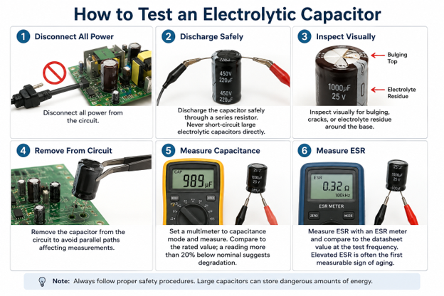
- Disconnect all power from the circuit.
- Discharge the capacitor safely through a series resistor. Never short-circuit large electrolytic capacitors directly.
- Inspect visually for bulging, cracks, or electrolyte residue around the base.
- Remove the capacitor from the circuit to avoid parallel paths affecting measurements.
- Set a multimeter to capacitance mode and measure. Compare to the rated value; a reading more than 20% below nominal suggests degradation.
- Measure ESR with an ESR meter and compare to the datasheet value at the test frequency. Elevated ESR is often the first measurable sign of aging and appears well before capacitance drops significantly.
Replacing Electrolytic Capacitors
When replacing an electrolytic capacitor, work through this checklist before sourcing a part:
Match the capacitance value. Use equal or higher voltage rating, never lower.
Match or exceed the temperature rating, especially in high-ambient environments such as near heat sinks or transformer cores.
Use a low ESR type wherever the original was a low ESR capacitor: substituting a standard general-purpose capacitor in a low-ESR position in a switching supply will cause premature failure and may damage surrounding components.
Confirm polarity before soldering. Match the package type and lead spacing or SMD footprint to avoid mechanical fit issues on the board.
How to Select the Right Electrolytic Capacitor
Picking a part by capacitance alone is one of the most common sourcing mistakes.
An electrolytic capacitor that meets the µF requirement but is mismatched on voltage, ESR, or temperature rating will underperform or fail.
The checklist below covers every parameter that matters, in the order you should evaluate them.
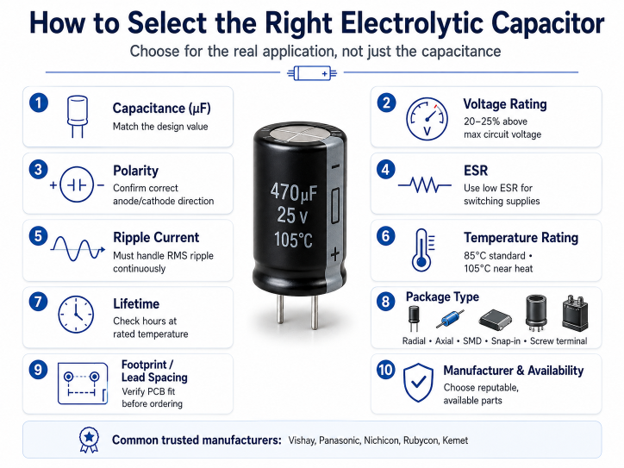
Selecting an electrolytic capacitor requires more than matching the capacitance value. Work through this list before finalizing a part:
- Capacitance (µF): Match the design specification exactly.
- Voltage rating: At minimum, 20–25% above the maximum circuit voltage, including transient spikes.
- Polarity: Confirm the circuit maintains the anode at higher potential than the cathode during all operating conditions.
- ESR: Specify low ESR electrolytic capacitors where ripple current is significant, particularly in switching supplies.
- Ripple current rating: The capacitor must handle the expected RMS ripple continuously without exceeding its thermal limit.
- Temperature rating: 85°C for standard environments; 105°C for locations near heat-generating components.
- Lifetime rating (hours at rated temperature): Important in industrial, automotive, and long-service applications.
- Package type: Radial, axial, SMD, snap-in, or screw-terminal, depending on PCB and assembly requirements.
- Lead spacing or SMD footprint: Confirm against the PCB layout before ordering.
- Manufacturer and availability: Vishay electrolytic capacitors, Panasonic, Nichicon, Rubycon, and Kemet are well-established sources.
For prototyping and repair work, an electrolytic capacitor kit covering a range of values and voltages is useful, but always confirm capacitance, voltage, ESR, and polarity match before substituting any part. Flywing Tech’s aluminum electrolytic capacitor catalog covers over 150,000 listings with full datasheet access for sourcing by exact specification.
Common Mistakes to Avoid
Reversing polarity is the most common installation error and causes immediate irreversible damage. Choosing a voltage rating too close to the operating voltage is the most common design error, especially when transients are present on the rail.
Ignoring ESR causes premature failure in switching power supplies. Substituting a standard general-purpose capacitor for a low ESR type in a switching supply is a frequent repair mistake that leads to early failure of both the replacement capacitor and sometimes the converter IC itself.
Ignoring the ripple current rating shortens service life rapidly through internal overheating. Using a polarized electrolytic capacitor in an AC-coupled position without specifying a bipolar type causes slow reverse-polarity degradation over time. Ignoring operating temperature is perhaps the costliest oversight: for every 10°C above the rated temperature, the operational life of an aluminum electrolytic capacitor roughly halves.
Final Thoughts
Electrolytic capacitors are among the most widely used passive components in electronics, but they are also among the most frequently misapplied.
Their high capacitance per unit volume makes them indispensable in power supply filtering, audio circuits, motor drives, and energy storage applications.
Their polarized construction and finite electrolyte lifetime mean they reward careful specification and penalise shortcuts.
The principles covered in this guide apply across the full electrolytic capacitor family: aluminum, tantalum, polymer, and bipolar types all share the same fundamental behaviour, even if the specifics of voltage range, ESR, failure mode, and lifetime differ between them.
Match the part to the application by working through capacitance, voltage, ESR, ripple current, temperature, and package in order, and most failures become avoidable.
For sourcing, Flywing Tech stocks over 150,000 aluminum electrolytic capacitor listings alongside tantalum, polymer, and bipolar types from manufacturers including Nichicon, Panasonic, Vishay, Rubycon, Kemet, and United Chemi-Con.
Whether you need a standard radial part for a repair job, a low-ESR SMD type for a switching supply, or a high-voltage snap-in capacitor for an industrial drive, thealuminum electrolytic capacitors catalog provides full datasheet access and competitive pricing across all package types and voltage ratings.
You can also explore tantalum capacitors andaluminum-polymer capacitors for applications where standard aluminum electrolytic types fall short.
FAQs About Electrolytic Capacitors
What is an electrolytic capacitor?
An electrolytic capacitor is a polarized capacitor that uses an electrochemically grown oxide layer as the dielectric and a liquid, gel, or solid electrolyte as part of the cathode system. It delivers much higher capacitance per unit volume than ceramic or film capacitors, making it the preferred choice for power supply filtering, audio coupling, and bulk energy storage.
What is electrolytic capacitor electrolyte?
The electrolyte in an electrolytic capacitor is a conductive liquid, gel, or solid material that sits between the oxide-coated anode foil and the cathode foil. It is not the dielectric. The electrolyte capacitor set of materials acts as the electrical cathode by conforming to the entire microscopic surface area of the oxide-coated anode, which is what makes high capacitance possible. Liquid electrolytes evaporate over time, which is the primary cause of capacitor aging and end-of-life.
Why are electrolytic capacitors polarized?
Electrolytic capacitors are polarized because the oxide dielectric only forms and remains stable when voltage is applied in the correct direction. Applying reverse voltage breaks down the oxide film, destroying the component.
How do I identify electrolytic capacitor polarity?
On leaded radial capacitors, the negative lead is shorter and the body has a stripe on the negative side. On SMD types, a stripe or marking indicates the negative terminal. In schematics, the + symbol marks the positive terminal of the electrolytic capacitor symbol.
What is the symbol of an electrolytic capacitor?
The schematic symbol for an electrolytic capacitor is a modified capacitor symbol with a + at the positive terminal. One plate is often curved to indicate the cathode, and a polarity marker is always present to distinguish it from non-polarized capacitors.
Can I replace an electrolytic capacitor with a ceramic capacitor?
For small values used in bypassing and decoupling, often yes. However, ceramic capacitors cannot practically replace large electrolytic capacitors in the hundreds or thousands of microfarads range, because ceramic technology cannot achieve those values in comparable package sizes at reasonable cost. Many designs intentionally combine both types: electrolytic for bulk energy, ceramic for high-frequency bypass.
What happens if an electrolytic capacitor is installed backwards?
Reverse polarity destroys the oxide dielectric rapidly. The capacitor draws excessive current, overheats, and will vent or rupture under continued reverse bias. The damage is essentially irreversible.
What is the difference between aluminum electrolytic and tantalum capacitors?
Aluminum electrolytic capacitors are larger, lower cost, and rated for higher voltages. Tantalum capacitors are more compact, offer better capacitance stability over temperature, cost more, and are more sensitive to surge currents. Tantalum capacitors can fail short under overvoltage; aluminum types more commonly fail open.
What does low ESR electrolytic capacitor mean?
A low ESR electrolytic capacitor has been specifically designed to minimize its internal series resistance through higher-conductivity electrolyte and optimized foil construction. Low ESR reduces internal heating from ripple current and is essential in switching power supply output stages and high-frequency filtering applications.
How long do electrolytic capacitors last?
Electrolytic capacitor lifetime is rated in hours at a specified temperature. A part rated for 2,000 hours at 105°C will last far longer when running at lower temperatures. The Arrhenius model approximates that lifetime doubles for every 10°C reduction in operating temperature. Keeping temperature low and ripple current within specification is the most effective way to maximize electrolytic capacitor lifespan.
How do you test an electrolytic capacitor?
Discharge the capacitor safely, remove it from the circuit, then measure capacitance and ESR using a multimeter and ESR meter. Compare both values to the datasheet. Visual inspection for bulging, cracking, or electrolyte leakage is also essential and sometimes reveals a failed capacitor before any electrical measurement is taken.
Can I use a higher voltage electrolytic capacitor as a replacement?
Yes. Using a higher voltage rating than the minimum required is electrically acceptable and generally improves reliability by increasing voltage margin. The only consideration is physical size: a higher-voltage capacitor may be physically larger, which must fit the available PCB space and lead spacing.

COMMENTS