Testing Electronic Components
Welcome back to our comprehensive guide on how to test electronic components! In Part 1, we covered the fundamental principles of multimeter use, voltage measurement techniques, and current measurement safety. Now it’s time to put those skills to work testing actual components.
In this second installment, we’ll go into the hands-on techniques to test electronic components which you’ll encounter frequently such as: resistors, capacitors, diodes, transistors, and inductors. You’ll learn not just how to test these components, but how to interpret the results, identify common failure modes, and avoid the mistakes that can lead to false readings.
Either you’re building a new project, troubleshooting a faulty circuit, or simply verifying components before installation, the techniques in this article will give you the confidence to test electronic components like a professional.

Workbench setup showing various electronic components
How Do I Test Electronic Components: Starting with Resistors
Resistors are among the easiest electronic components to test, making them perfect for practicing your multimeter skills. However, there are several important considerations that can affect the accuracy of your measurements when you test electronic components.
How Do I Read Resistor Color Codes Before Testing?
Before you test electronic components like resistors, you need to know their expected values. Most through-hole resistors use a color band system to indicate their resistance value and tolerance.
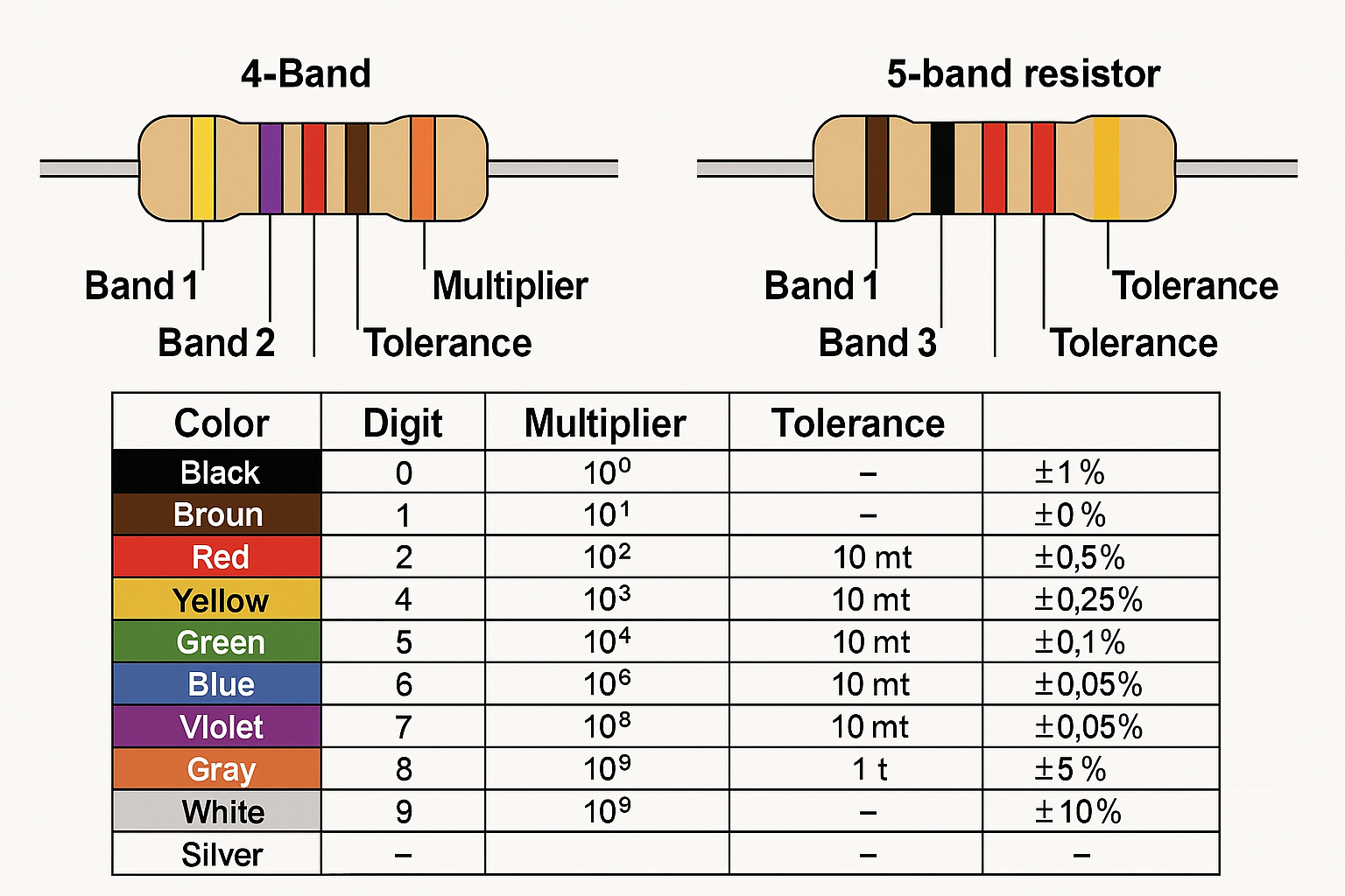
Close-up diagram of a 4-band and 5-band resistor showing color bands with labels and a color code chart below
4-Band Resistor Code:
- Band 1: First digit
- Band 2: Second digit
- Band 3: Multiplier (number of zeros)
- Band 4: Tolerance (usually gold = ±5%, silver = ±10%)
5-Band Resistor Code:
- Bands 1-3: Three significant digits
- Band 4: Multiplier
- Band 5: Tolerance
Common Color Values:
- Black = 0, Brown = 1, Red = 2, Orange = 3, Yellow = 4
- Green = 5, Blue = 6, Violet = 7, Gray = 8, White = 9
Memory aid: “Big Boys Race Our Young Girls But Violet Generally Wins”
What’s the Best Method to Test Electronic Components: Resistor Measurement
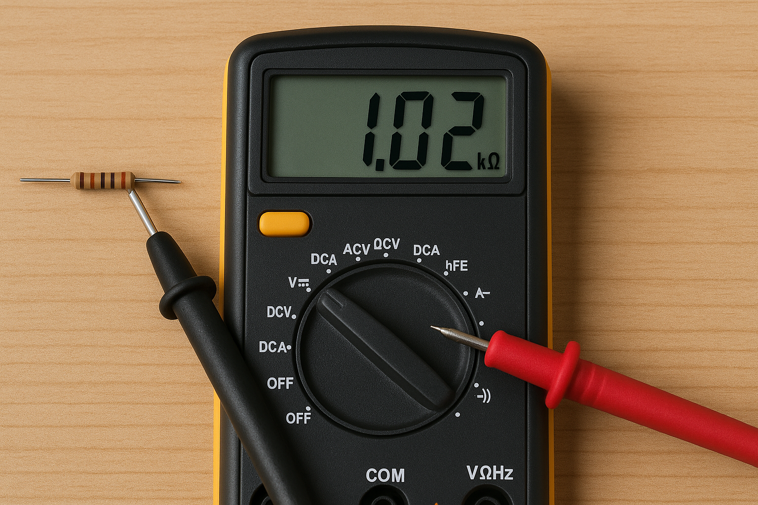
Digital multimeter set to resistance mode
- Set your multimeter to resistance (Ω) mode
- Choose an appropriate range – Start with auto-range or the next higher range than expected
- Remove the resistor from the circuit (critical for accurate readings)
- Touch probes to either end – Polarity doesn’t matter for resistors
- Wait for reading to stabilize – This is especially important for high-value resistors
- Compare with expected value – Account for tolerance rating
Key Safety Points:
- Never test resistance with power applied to the circuit
- Your body resistance can affect readings on high-value resistors – avoid touching the probe tips
- Clean oxidized or dirty component leads for better contact
Why Can’t I Test Electronic Components In-Circuit?
Testing resistors in-circuit often gives misleading results due to parallel paths. Other components connected to the resistor create parallel resistance paths that alter your reading. The measured value will always be lower than the actual resistor value because parallel resistances always decrease total resistance.
When In-Circuit Testing Might Work:
- One end of the resistor connects to an isolated point
- You can lift one end of the resistor
- You’re using specialized in-circuit testers designed to compensate for parallel paths
What Do Different Resistor Failures Look Like?
Open Resistor:
- Multimeter shows “OL” (overload) or infinite resistance
- Often caused by overheating, physical damage, or age
- Visually may show burn marks, cracks, or color changes
Short Circuit:
- Shows very low or zero resistance
- Rare in carbon film resistors, more common in wire-wound types
- Usually indicates severe overheating or physical damage
Value Drift:
- Reading outside tolerance range but not completely open
- Common in older carbon composition resistors
- Can be caused by humidity, temperature cycling, or aging
Intermittent Connection:
- Reading fluctuates or changes when the component is moved
- Often caused by cracked solder joints or internal wire breaks
- Analog meters are better for detecting this type of failure
How to Test Electronic Components: Capacitor Testing Techniques
Capacitor testing is more complex than resistor testing because you need to verify both the capacitance value and the component’s ability to hold and release charge. Different types of capacitors also have different failure modes and testing requirements when you test electronic components.
What’s the Safest Way to Discharge Capacitors Before Testing?
Critical Safety Warning: Large capacitors can hold dangerous charges even when power has been removed from a circuit. Always discharge capacitors before you test electronic components.
For Large Electrolytic Capacitors (>100µF):
- Use an insulated screwdriver to short the terminals
- Or use a high-wattage resistor (1kΩ, 5W) across the terminals
- Wait several seconds for complete discharge
- Verify with voltmeter that no voltage remains
For Small Capacitors:
- Usually safe to handle, but still good practice to discharge
- Touch with insulated probe tips briefly
How Do I Measure Capacitance When I Test Electronic Components?
Most modern digital multimeters include capacitance measurement capability when you test electronic components:
[IMAGE NEEDED: Digital multimeter in capacitance mode with probes connected to an electrolytic capacitor, display showing capacitance reading in microfarads]
- Set multimeter to capacitance mode (usually marked with capacitor symbol)
- Discharge the capacitor completely
- Select appropriate range – Start with auto-range or next higher range
- Connect probes to capacitor terminals – Polarity usually doesn’t matter for measurement
- Wait for reading to stabilize – Large capacitors take longer to read
- Compare with labeled value – Typical tolerance is ±10-20%
Important Notes:
- Remove capacitor from circuit for accurate readings
- Some meters require special test leads for capacitor measurement
- Very small capacitors (pF range) may need specialized equipment
What is ESR and Why Should I Test It?
Equivalent Series Resistance (ESR) is particularly important for electrolytic capacitors. A capacitor can show correct capacitance but still be faulty due to high ESR, which affects its performance in filtering and timing circuits.
Normal ESR Values:
- Small electrolytics (1-100µF): 1-5 ohms
- Medium electrolytics (100-1000µF): 0.1-1 ohm
- Large electrolytics (1000µF+): 0.01-0.1 ohm
High ESR Symptoms:
- Power supply ripple and noise
- Timing circuit problems
- Reduced filtering effectiveness
- Overheating in switching circuits
ESR Testing Methods:
- Dedicated ESR meters (most accurate)
- Some advanced multimeters include ESR function
- In-circuit ESR testers (can test without removal)
How Do I Perform a Charge and Discharge Test?
This test verifies that a capacitor can actually store and release charge:
- Set multimeter to DC voltage mode
- Apply known DC voltage to charge the capacitor – Use voltage within the capacitor’s rating
- Remove voltage source and immediately measure capacitor voltage
- Observe voltage decay over time
What to Look For:
- Good capacitor should initially show close to applied voltage
- Voltage should decay slowly (time depends on capacitor size and multimeter input impedance)
- Rapid discharge indicates leakage or internal short
- No initial voltage indicates open capacitor
Professional Methods to Test Electronic Components: Diode Testing
Diodes are essentially one-way valves for electrical current, making their basic testing straightforward once you understand the principles. However, different types of diodes have different characteristics that affect your test results when you test electronic components.
What’s the Proper Way to Test a Diode with a Multimeter?
Most modern multimeters have a dedicated diode test mode that applies a small current and measures the forward voltage drop:
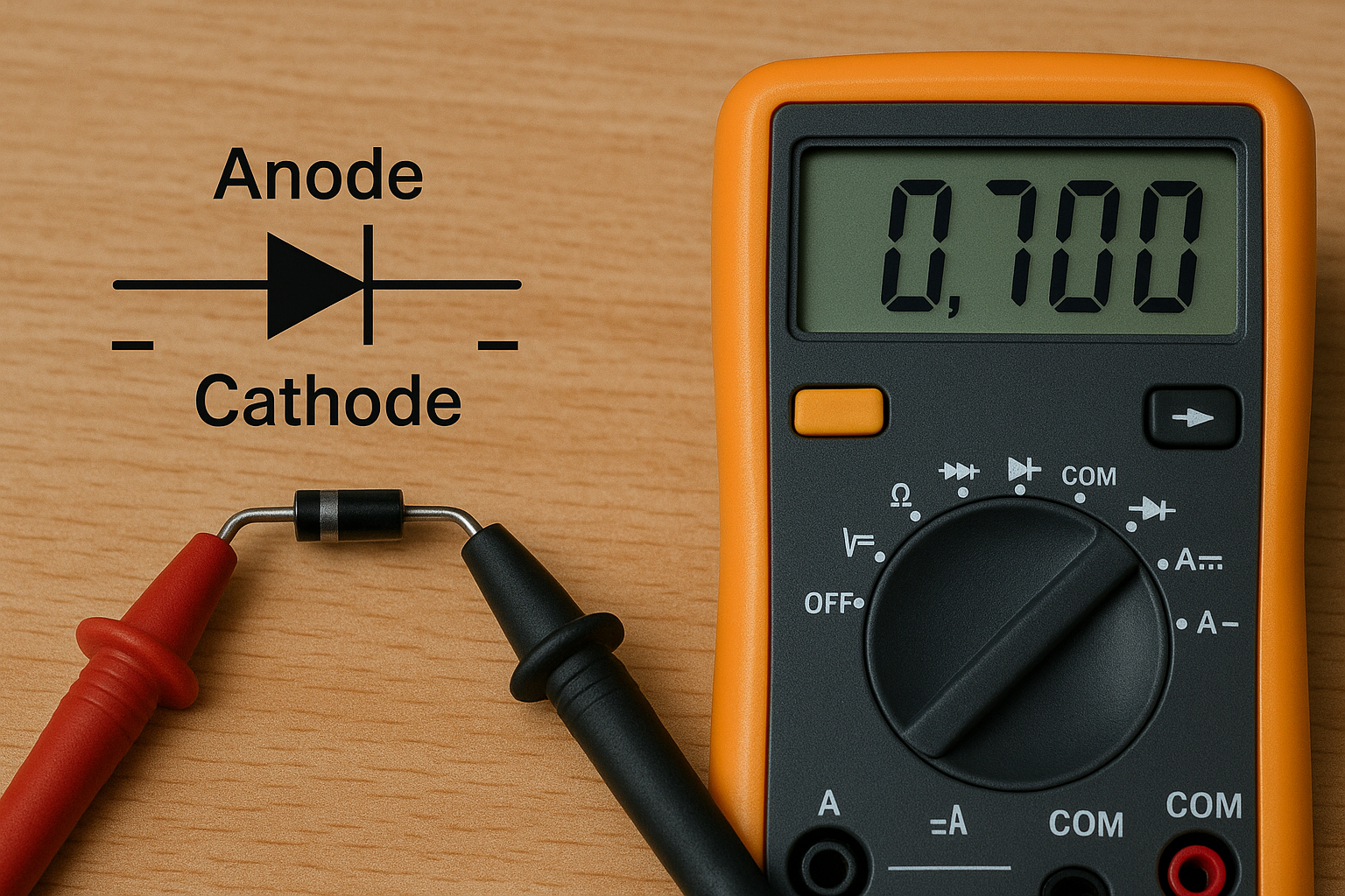
Multimeter in diode test mode
- Set multimeter to diode test mode (usually marked with diode symbol)
- Connect red probe to anode (+) and black probe to cathode (-)
- Read the forward voltage drop – Should be 0.6-0.7V for silicon diodes
- Reverse the probes – Should show “OL” or very high resistance
- Compare results with expected values for diode type
Alternative Method Using Resistance Mode:
- Forward bias: Should show low resistance (few hundred ohms)
- Reverse bias: Should show very high resistance (megohms)
- This method is less precise but works on any multimeter
How Do I Identify Different Types of Diodes?

Collection of different diode types laid out with labels – silicon diode, Schottky diode, Zener diode, LED
Silicon Diodes (Most Common):
- Forward voltage drop: ~0.7V
- Used in most rectifier and switching applications
- Can handle higher temperatures than germanium
Schottky Diodes:
- Forward voltage drop: ~0.2-0.4V
- Fast switching speed, lower forward drop
- Common in switching power supplies
Germanium Diodes (Rare):
- Forward voltage drop: ~0.3V
- Mainly found in vintage equipment
- More temperature sensitive than silicon
Zener Diodes:
- Forward test same as regular diode (~0.7V)
- Reverse breakdown at specific voltage (zener voltage)
- Requires special test setup to verify zener voltage
Light Emitting Diodes (LEDs):
- Forward voltage drop varies by color:
- Red: ~1.8-2.2V
- Green/Yellow: ~2.0-2.4V
- Blue/White: ~3.0-3.6V
- May light dimly during diode test
- Higher forward voltage than regular diodes
What Do Faulty Diodes Look Like in Testing?
Shorted Diode:
- Shows low resistance in both directions
- Forward and reverse readings are similar
- Usually caused by overvoltage or overcurrent damage
Open Diode:
- Shows infinite resistance in both directions
- No conduction in forward or reverse bias
- Can be caused by physical damage or thermal stress
Leaky Diode:
- Shows normal forward conduction
- Shows some conduction in reverse direction (should be very high resistance)
- Indicates degraded junction, may cause circuit malfunction
Intermittent Diode:
- Readings change when component is moved or heated
- Can be very difficult to detect
- Often caused by micro-cracks in the junction
How Do I Test LEDs Without Damaging Them?
LEDs are more delicate than regular diodes and can be damaged by too much current:
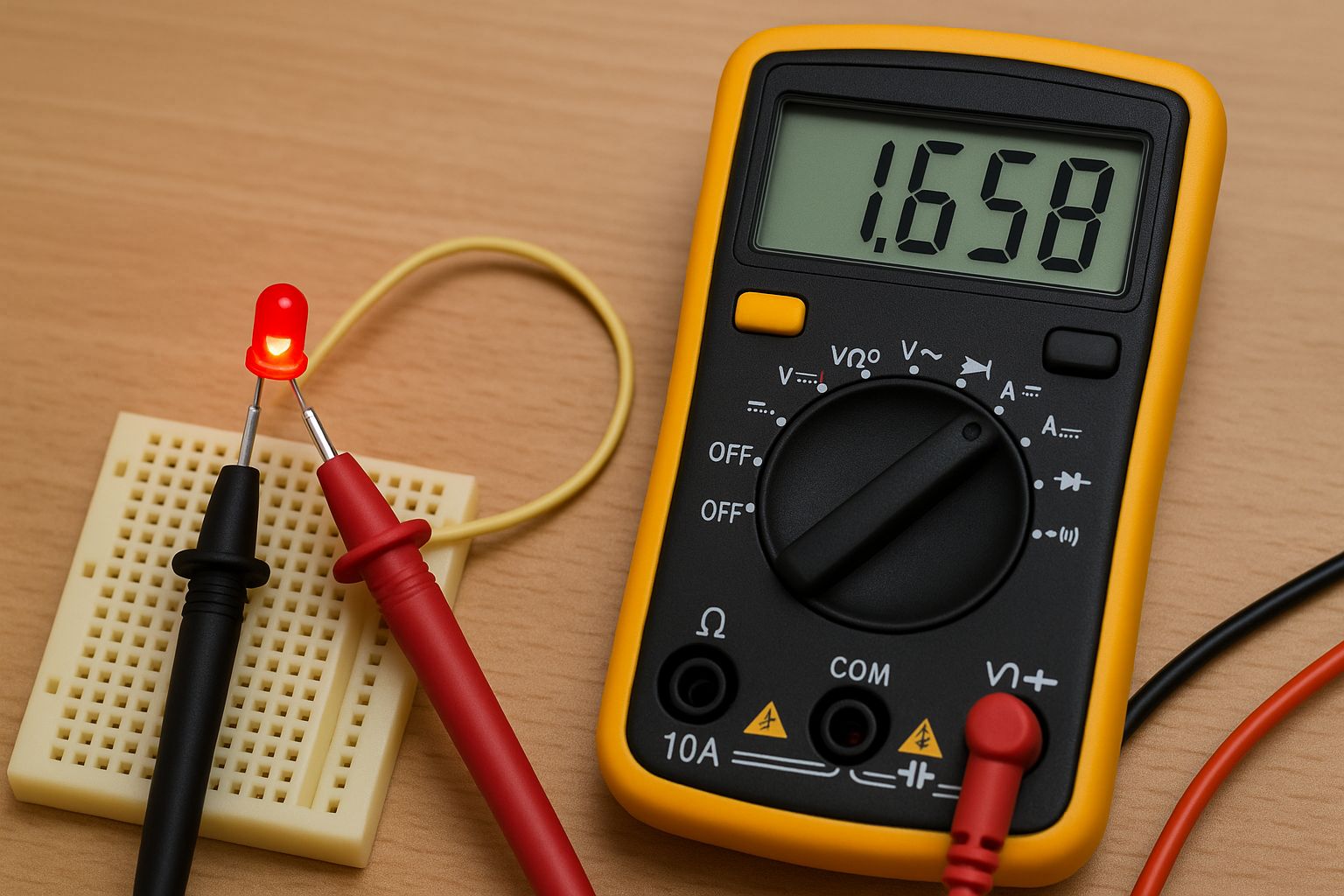
LED testing setup showing multimeter
Safe LED Testing:
- Use diode test mode – Provides current-limited test voltage
- Watch for light emission – LED should glow dimly during forward test
- Check forward voltage – Should match expected value for LED color
- Verify no reverse conduction – Should show “OL” in reverse
What Not to Do:
- Don’t use resistance mode for LED testing – can provide too much current
- Don’t exceed maximum forward current rating
- Don’t apply reverse voltage above 5V (can damage LED junction)
Component Spotlight & Deep Dives
Spotlight: Electrolytic Capacitors – The Troublemaker’s Friend
Electrolytic capacitors are among the most failure-prone components in electronic equipment, making them a prime target when you test electronic components for troubleshooting efforts. Understanding their unique characteristics and failure modes can save you countless hours of diagnostic work.
Why Electrolytics Fail More Often:
- Liquid electrolyte can dry out over time
- Sensitive to temperature and ripple current
- Limited lifespan compared to other capacitor types
- Prone to reverse voltage damage
Visual Inspection Clues:
- Bulging or swollen tops indicate internal pressure buildup
- Leaked electrolyte appears as brown, crusty residue
- Discolored or corroded terminals suggest long-term leakage
- Cracked or damaged sleeves expose internal construction
Advanced Testing Techniques:
- Ripple current capability: Measure ESR at various frequencies
- Temperature coefficient: Test capacitance at different temperatures
- Leakage current: Apply rated voltage and measure DC leakage
- Life expectancy: Calculate remaining life based on temperature history
Deep Dive: Power MOSFETs – Beyond Basic Testing
Power MOSFETs require more sophisticated testing than small-signal transistors due to their construction and application requirements.
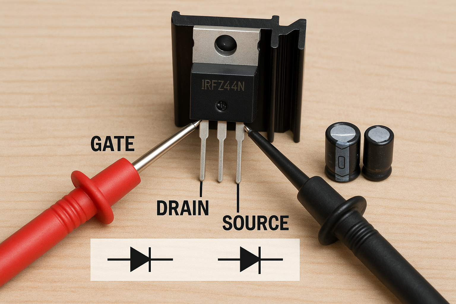
Power MOSFET with heat sink, showing gate, drain, and source terminals
Gate Threshold Voltage Testing: The gate threshold voltage (Vth) determines when the MOSFET begins to conduct. This parameter can shift with age and temperature.
Test Procedure:
- Set up variable voltage source for gate
- Apply small drain-source voltage (1V)
- Gradually increase gate voltage while monitoring drain current
- Note voltage where drain current begins to flow
- Compare with datasheet specifications
Body Diode Testing: All MOSFETs contain an internal body diode that can be tested like any other diode:
- Connect multimeter in diode mode between source and drain
- Should show forward voltage drop (~0.7V) in one direction
- Should show “OL” in reverse direction
- Body diode orientation depends on N-channel vs P-channel type
Spotlight: SMD Resistors – When You Test Electronic Components in Modern Devices
Surface-mount device (SMD) resistors present unique challenges due to their small size and different marking systems when you test electronic components.
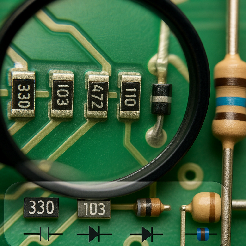
Close-up macro photo of SMD resistors on a circuit board with magnifying glass, showing size comparison to through-hole components, with code markings visible
SMD Resistor Code Systems:
3-Digit Code (Most Common):
- First two digits: significant figures
- Third digit: multiplier (number of zeros)
- Example: 473 = 47,000 ohms (47kΩ)
4-Digit Code (Precision Resistors):
- First three digits: significant figures
- Fourth digit: multiplier
- Example: 4701 = 4,700 ohms (4.7kΩ)
Letter Codes (Very Small Resistors):
- Use letters to represent decimal points
- R = decimal point, K = thousands, M = millions
- Example: 4R7 = 4.7Ω, 4K7 = 4.7kΩ
Testing Challenges and Solutions:
Physical Handling:
- Use tweezers with fine, smooth tips
- Anti-static precautions more critical due to small mass
- Magnification often necessary for code reading
- Easy to lose – work over contained area
Electrical Testing:
- Standard multimeter probes often too large
- Use needle-point probes or micro-clips
- More susceptible to body capacitance effects
- Thermal effects from probe contact can affect readings
Frequently Asked Questions
Can I test electronic components while they’re still in the circuit?
Short answer: Sometimes, but it’s not recommended for accurate results.
Detailed explanation: In-circuit testing can give misleading results because other components create parallel paths that affect your measurements. This is especially problematic for:
- Resistors: Parallel components always make the reading lower
- Capacitors: Other capacitors and inductors affect readings
- Semiconductors: Bias networks can interfere with junction testing
When in-circuit testing might work:
- One end of the component is isolated (connected only to test point)
- You’re using specialized in-circuit testers
- You’re only looking for gross failures (shorts, opens)
- The circuit is designed with test points for in-circuit measurement
Best practice: Remove at least one end of the component for accurate testing.
Why do my readings change when I touch the probes?
This is a common issue with several possible causes:
Body Capacitance:
- Your body acts as a capacitor to ground
- Affects high-impedance measurements most
- More noticeable with high-value resistors and small capacitors
- Solution: Avoid touching probe tips, use shorter test leads
Poor Contact:
- Oxidized or dirty component leads
- Loose probe connections
- Intermittent component failure
- Solution: Clean contacts, ensure firm connections
What’s the difference between testing new vs. used components?
New Components:
- Should test within specified tolerance
- No thermal stress history
- Clean leads and markings
- May need burn-in for critical applications
Used Components:
- May have drifted outside original tolerance
- Possible thermal stress damage
- Oxidized or corroded leads affecting contact
- Unknown operating history affects reliability
How do I know if my multimeter is accurate enough?
Basic Accuracy Check:
- Test with known precision resistors
- Compare readings between different meters
- Check calibration certificate date (if available)
- Verify readings against component marked values
Accuracy Specifications:
- Basic meters: ±2-3% typical
- Good quality meters: ±0.5-1% typical
- Professional meters: ±0.1-0.25% typical
- Laboratory standards: ±0.01% or better
What components can’t be tested with a basic multimeter?
Several component types require specialized test equipment:
High-Frequency Components:
- RF transistors and diodes
- Microwave components
- High-speed digital logic
- Need: Network analyzers, spectrum analyzers
Complex Integrated Circuits:
- Microprocessors
- Memory devices
- Analog ICs with multiple functions
- Need: Logic analyzers, pattern generators, specialized IC testers
Is it safe to test electronic components from old electronics?
Generally safe, but take precautions:
Potential Hazards:
- Stored energy: Large capacitors can hold dangerous charges for long periods
- Toxic materials: Very old components may contain hazardous materials
- Sharp edges: Broken components can cause cuts
- Chemical residues: Leaked electrolytes can be corrosive
Safety Precautions:
- Discharge all capacitors before handling
- Wear safety glasses when handling brittle components
- Work in well-ventilated area
- Dispose of damaged components properly
- Wash hands after handling old electronics
How do I test electronic components without markings or datasheets?
Systematic Approach:
1. Visual Identification:
- Package type and size
- Number of pins/leads
- Physical construction clues
- Semiconductor junction visibility
2. Basic Electrical Tests:
- Resistance between all pins
- Diode tests between pins
- Capacitance measurements where applicable
- Look for patterns suggesting component type
3. Research Techniques:
- Component identification apps
- Online databases
- Electronics forums and communities
- Cross-reference with similar known components
What’s Coming Next?
The foundation you’ve built in Parts 1 and 2 – understanding multimeter principles and mastering how to test electronic components – will serve you well as you move into more sophisticated testing scenarios.
Quick Reference Glossary
Anode – Positive terminal of a diode, LED, or similar component
Body Diode – Internal diode present in all MOSFETs due to construction
Cathode – Negative terminal of a diode, LED, or similar component
ESR – Equivalent Series Resistance, important in capacitor performance
Forward Bias – Applying voltage to make a diode conduct
Leakage Current – Small current that flows when a component should be blocking
Reverse Bias – Applying voltage to block conduction in a diode
SMD – Surface Mount Device, components designed for surface mounting
Threshold Voltage – Minimum voltage needed to turn on a MOSFET
Tolerance – Acceptable variation from nominal component value
Join the Conversation
Now that you’ve learned to test electronic components individually, we’d love to hear about your experiences! Have you discovered any interesting component failures using these techniques? What’s the most unusual component you’ve had to test without a datasheet?
Share your component testing victories and challenges in the comments below. Whether you’ve saved a vintage radio by finding a single bad capacitor or discovered a tricky intermittent resistor failure, your experiences help build our community knowledge base.
Let us know what challenges you’re facing in your electronic projects!