Why Decoupling Capacitor Placement Kills More Designs Than Value Selection
Your microcontroller just reset again. The culprit? Poor decoupling capacitor placement. That 0.1µF ceramic cap sitting 2cm from your MCU might as well not exist. At 100MHz switching speeds, decoupling capacitor placement is everything—the difference between a working prototype and an expensive paperweight
Decoupling capacitors are one type of electrical component that appears in almost all digital electronic circuits/systems found today. They are active devices in electronic systems (transistors, integrated circuits, vacuum tubes, etc.) connect to their power supplies through conductors that exhibit finite resistance and inductance.
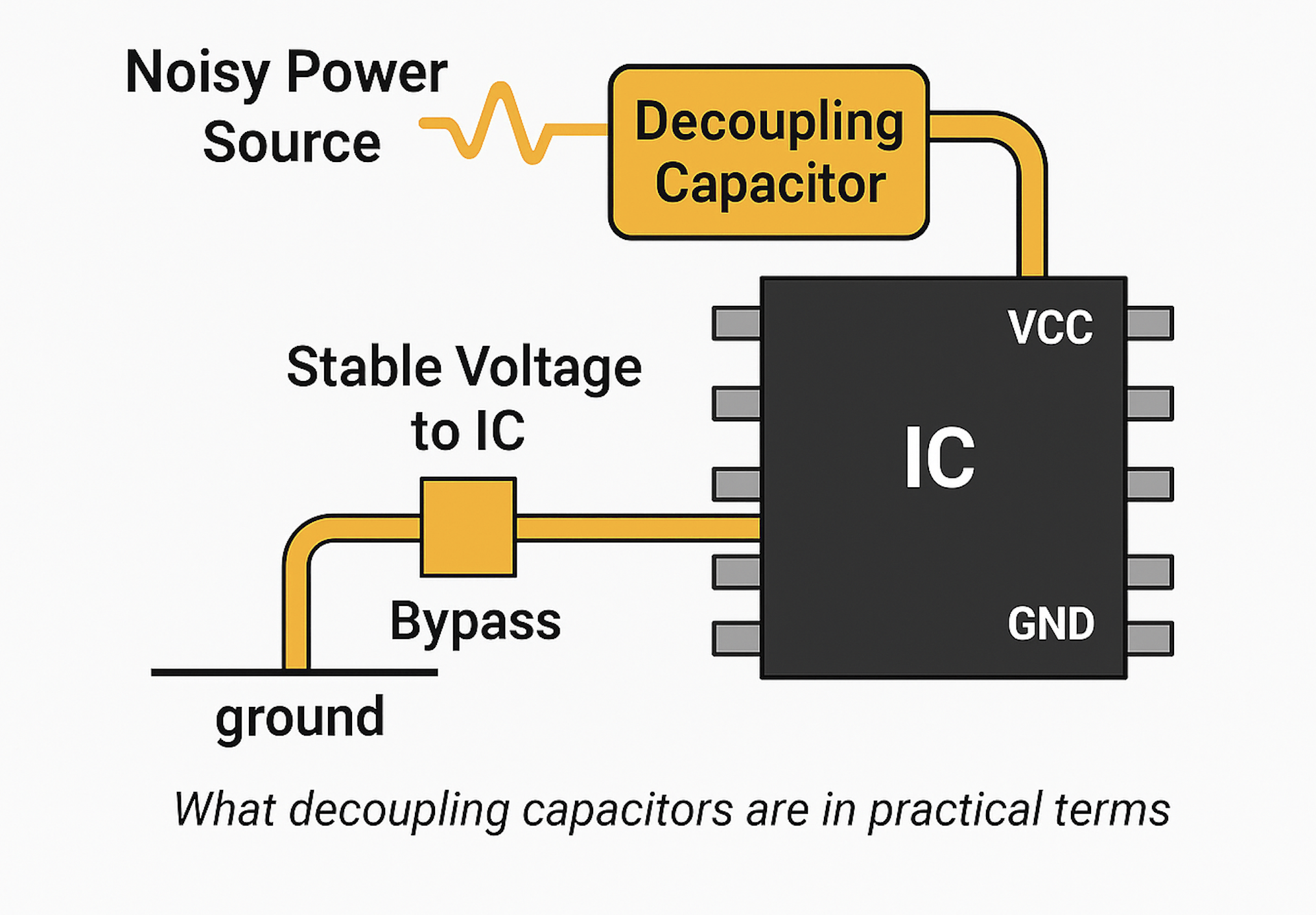
When the current drawn by an active device changes, the voltage drop from the power supply to the device also changes due to these impedances. If several active devices share a common path to the power supply, changes in the current drawn by one element may produce voltage changes large enough to affect the operation of others – voltage spikes or ground bounce, for example – so the change of state of one device is coupled to others through the common impedance to the power supply. A decoupling capacitor placement provides a bypass path for transient currents, instead of flowing through the common impedance.

decoupling capacitor placement
The decoupling capacitor functions as the device’s local energy storage. The decoupling capacitor placement should be between the power line and the ground to the circuit where the current is to be provided. According to the capacitor current–voltage relation i(t)=Cdv(t)dt, a voltage drop between a power line and the ground results in a current drawn out from the capacitor to the circuit. When capacitance C is large enough, sufficient current is supplied to maintain an acceptable range of voltage drop.
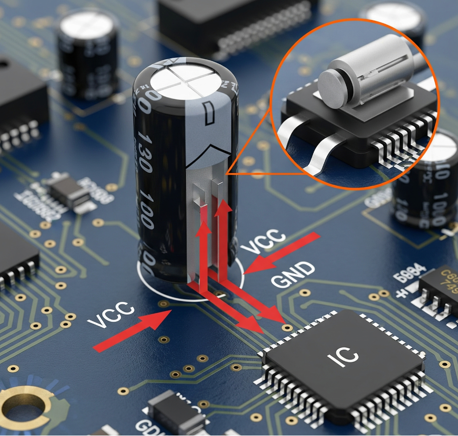
A zoomed-in illustration of a capacitor between VCC and GND pins on a PCB
Decoupling Capacitor Placement Layout Guidelines
The capacitor stores a small amount of energy that can compensate for the voltage drop in the power supply conductors to the capacitor. To reduce undesired parasitic equivalent series inductance, small and large capacitors are often placed in parallel, adjacent to individual integrated circuits.
functions of a decoupling capacitor placement
When a microcontroller resets randomly, the root cause is often traced to poor decoupling capacitor placement
I remember when I was working on a small sensor device that I used a button cell battery to power it. The setup used a PIC microcontroller and would wake up every now and then to send data. On my desk, everything worked fine. But in the field, sometimes it wouldn’t turn back on right after changing the battery. It looked dead. Then, suddenly, it would start working again after 20–30 seconds.
At first, I thought it was a power or code issue. But after checking everything, I found the real cause: the decoupling capacitors were holding charge even after the battery was removed. Since the microcontroller used very little power in sleep mode, the voltage didn’t drop low enough to fully reset it. So when power came back, the chip did not restart, but it remained in a partially working state.
To fix it, I added a resistor to slowly drain the leftover charge and used a reset chip to make sure the microcontroller always restarted cleanly.
That’s when I learned that just removing the battery doesn’t always mean your system is completely powered off; those small capacitors can keep it “half-awake” and cause strange problems.
Why doesn’t just picking a 0.1 µF capacitor solve power noise problems?
Most Engineers choose a decoupling capacitor by looking at its value, for example, 0.1 µF, 1 µF, or 10 µF. That’s a good start, but it does not tell you the whole story.
The Capacitance value tells you how much charge the capacitor can store. It purpose is to help smooth out slow voltage dips, because as switching speeds increase, the noise gets faster and higher in frequency. And by noise i mean voltage Spikes or overshoot
To put it candidly, every time a digital IC switches states ( from 0 to 1), it draws a sudden high amount of current from the power source. So, If your decoupling network and layout is not good, this causes the noise we mentioned above
Always be mindful that If your microcontroller or FPGA switches at 100 MHz, the power supply doesn’t just need a bulky capacitance. It requires a capacitor that can respond fast enough to those high-frequency events. And that’s where SRF and ESR come in.
What Frequency Range Are We Talking About?
- Low-speed switching (basic MCUs): 100 kHz to a few MHz
- Medium-speed digital (Wi-Fi chips, Cortex-M4): 10 MHz–100 MHz
- High-speed logic (FPGAs, DDR memory): 100 MHz–500+ MHz
Decoupling Capacitor Placement vs. Power Plane Performance
At those frequencies, capacitances like 10 µF are too slow to respond. This is why you need small, high-SRF ceramic capacitors placed close to the IC to remove that noise before it damages your logic levels or radiates as EMI.
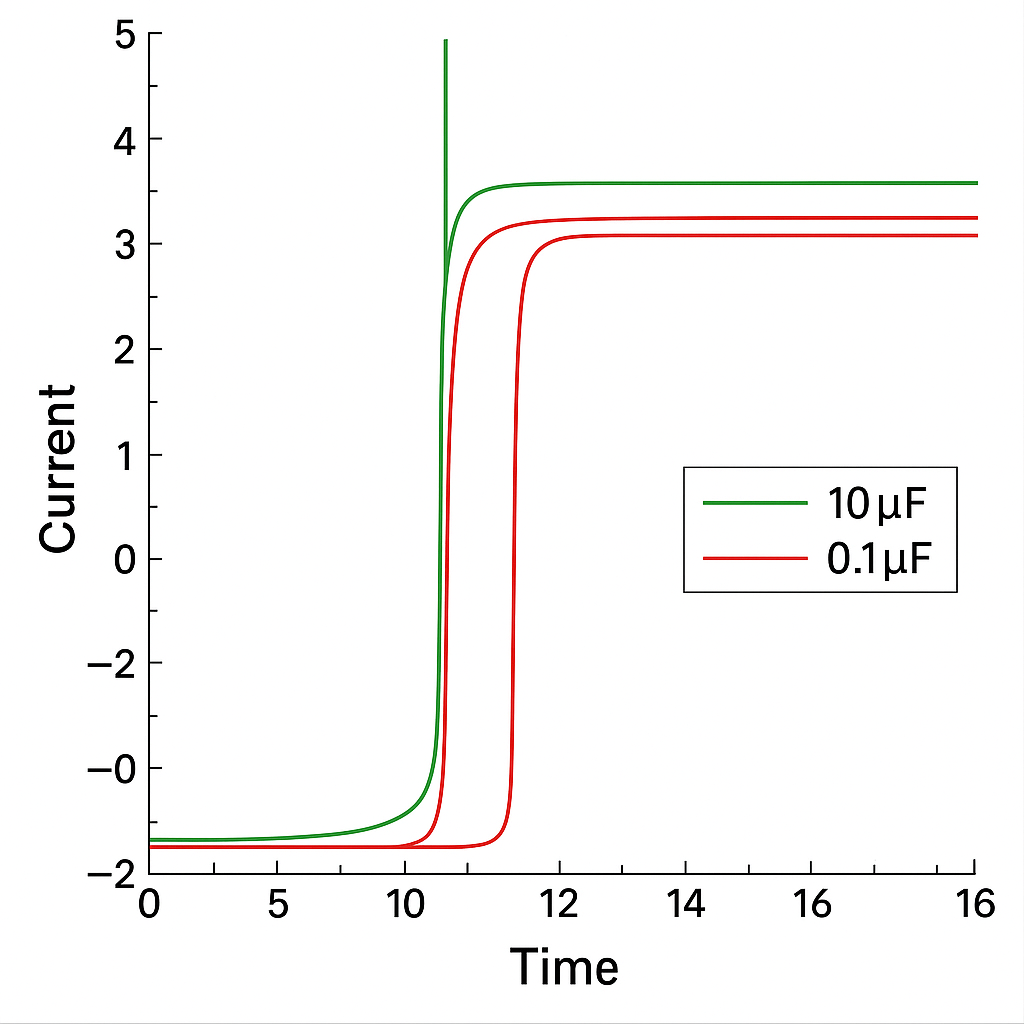
A graph showing current spike during an IC switching event.
SRF: Self-Resonant Frequency is The “Speed Limit” of a decoupling capacitor placement
Let me tell you a secret: Every capacitor behaves like more than just a capacitor. It also has these two unique quality:
- A bit of series resistance (ESR)
- A bit of inductance (ESL — Equivalent Series Inductance)
You need to know that a capacitor’s performance is governed by its total impedance (Z), which includes its Equivalent Series Resistance (ESR) and Equivalent Series Inductance (ESL). The formula for a capacitor’s impedance at a given frequency (f) is:
Where:
- X_L is the inductive reactance:
$$X_L = 2\pi f \cdot \text{ESL}$$ - X_C is the capacitive reactance:
$$X_C = \frac{1}{2\pi f \cdot C}$$
The Self-Resonant Frequency (f_SRF) is the point where the inductive reactance equals the capacitive reactance (X_L = X_C), making the capacitor’s impedance reach its absolute minimum (equal to its ESR). This is calculated as:
$$f_{\text{SRF}} = \frac{1}{2\pi \sqrt{\text{ESL} \cdot C}}$$
At this frequency, the capacitor is most effective at shunting high-frequency noise.
This means that while operating it at some frequency, the capacitor’s inductive behavior cancels out its capacitive behavior. That frequency is called the Self-Resonant Frequency (SRF).
Below SRF: the cap behaves like a capacitor
At SRF: impedance is lowest — best noise filtering
Above SRF: the cap acts like an inductor, and becomes useless
So if you pick a 10 µF cap thinking you have made the best choice, not realising that its SRF is 300 kHz, it won’t work to block a 50 MHz voltage spike. You need a smaller-value cap (like 0.1 µF or 0.01 µF) with a higher SRF to suppress that kind of noise.
Use this to make your decision
| Cap Value | Typical SRF | Best For Filtering |
| 10 µF | ~0.3 MHz | Low-speed drop / startup transients |
| 1 µF | ~3 MHz | Low-frequency switching noise |
| 0.1 µF | ~30 MHz | Medium-speed digital noise |
| 0.01 µF | ~200 MHz | High-speed edge spikes (EMI) |
At its core, the capacitor’s impedance is frequency dependent:
$$Z(f) = \frac{1}{2\pi f C}$$
But real capacitors also include ESL (L) and ESR (R), turning it into an RLC network gives:
$$Z(f) = \sqrt{R^2 + \left(2\pi f L – \frac{1}{2\pi f C}\right)^2}$$
The frequency at which inductive and capacitive reactance cancel out is called the Self-Resonant Frequency (SRF):
$$f_{\text{SRF}} = \frac{1}{2\pi \sqrt{L C}}$$
Equivalent Series Resistance is use to Controls Damping
ESR determines how “resistive” the capacitor is at its working frequencies.
- Low ESR = better noise suppression
- Zero ESR = can cause ringing or anti-resonance when you use multiple capacitors
If you mix several capacitors (say, 0.1 µF and 10 µF), their SRFs can interfere and create spikes on your power rail unless their ESRs are balanced. That’s why you sometimes want a bit of ESR to absorb that energy without resonance.
Why even picking the Best Capacitor Can Still Fail
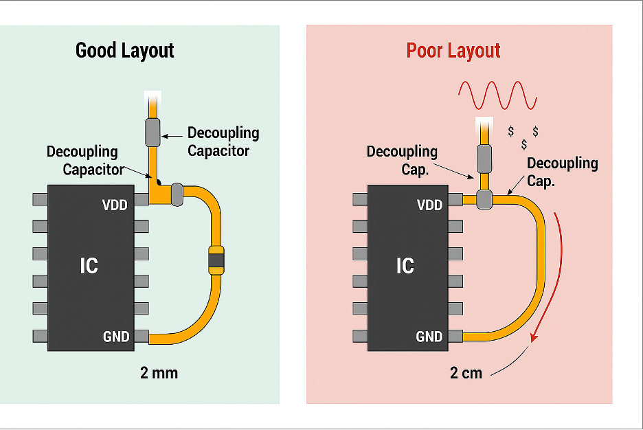
Even if you pick the perfect capacitor value, SRF, and ESR, it can still fail altogether if you place it wrong on the PCB. this is why decoupling capacitor placement matters
Here’s what kills decoupling performance:
- Long traces from capacitor to IC pin = high inductance
- Shared vias or power routing = noisy return path
- Far away placement = slow energy delivery = transient spikes
- Poor ground = loop area increases → more radiated EMI
Think about this: A 0.1 µF capacitor placed 2 mm from the VDD pin is effective.
The same cap placed 2 cm away? Might as well not be there.
The capacitor should be placed as close as possible to the IC’s power pin, with a short, direct connection to ground. Ideally, this connection should utilize multiple vias and a solid ground plane underneath.
The effectiveness of the bypass loop depends on the loop inductance (L), which increases with trace length and area.
Inductance roughly scales as:
$$L \approx \frac{\mu \cdot l}{w}$$
Where:
$$\begin{align*}
l & = \text{loop length} \\
w & = \text{trace width} \\
\mu & = \text{permeability of the material}
\end{align*}$$
Smaller loop = less inductance = faster response.
Let me give a simple analogy to explain this concept.
Your power source is like a water pipe supplying water(current). While Fast-switching ICs are like someone opening and closing the pipe 100 million times a second. which will create pressure ripples (voltage noise) that bounce back unless you have “shock absorbers” (decoupling capacitors) tuned to the right frequency.
Multilayer Ceramic Capacitors (MLCCs)
What does a decoupling capacitor do on a PCB?
We have mentioned previously that when an IC quickly switches its logic states, it needs a sharp burst of curren right?. But the problem is that the current can’t travel from your power supply fast enough, it’s too far, and the traces (thin copper lines on a printed circuit board (PCB)) act like inductors. At this point that’s where the decoupling capacitor steps in. It’s works like a battery sitting right next to the IC. It supplies energy instantly, smoothing out the voltage and keeping everything stable.
Why does my microcontroller need caps right next to it? Can’t the power plane handle it?
Let’s be very clear, your central power plane (solid layer of copper for carrying either power (VDD) or ground (GND)) cannot handle the current demands of your Microcontroller, because at high speeds, it’s too slow. The inductance in the traces and power planes adds delay. A decoupling capacitor placed just 1–2 mm away provides a much faster, low-impedance path to get the charge it needs. That’s why proximity isn’t optional, it’s essential.
How do decoupling capacitor placement stop high-frequency noise?
We have all agreed that When an IC switches it states, it creates high-frequency voltage spikes on the power rail. They appear tiny and fast, and they ride on top of your voltage line. A decoupling capacitor will filter them out by acting like a shortcut to the ground. At high frequencies, it has very low impedance, so it “sinks” the spike before it can cause any trouble. The smaller the cap, the better it works at higher frequencies.
decoupling capacitor placement:Why do engineers use more than one capacitor per chip?
No single capacitor can clean all the noise your chip will create. A 10 µF capacitor is great for slow voltage dips but becomes useless above a few MHz. A 0.01 µF capacitor will not help at startup but will kill high-frequency spikes. That’s why engineers stack them by using multiple values together to cover the whole frequency range. In essence, bulk capacitors handle slow changes, and smaller capacitors deal with fast ones.
Each capacitor handles a portion of the frequency spectrum.
$$f_{\text{cutoff}} \approx \frac{1}{2\pi R C}$$
Using this, a 0.1 µF capacitor with a 1 Ω path impedance filters noise around:
$$f \approx 1.6\,\text{MHz}$$
This shows why you need a mix of smaller capacitors that cutoff frequency higher.
Common Failure Cases and How to Spot Them
Why is placing all decoupling caps near the regulator a bad idea?
Let me share an experience, I once saw a board where every decoupling capacitor was placed neatly around the LDO, but none near the actual microcontroller. The board passed functional tests, but occasionally glitched during Wi-Fi transmission. It turns out that the switching noise was never being filtered at the source. The capacitors were just too far from the IC. Decoupling capacitor placement matters, they will help you if they’re right next to the switching node. Otherwise, you will just be feeding noise through a long, delayed power rail.
What happens if I skip small-value capacitors like 0.01 μF?
A common mistake some engineers make is to think 10 μF or 1 μF caps are “enough.” But without a 0.01 μF or 0.1 μF cap, you leave the high-frequency end wide open. I’ve seen this lead to hard-to-catch logic errors, like random GPIO glitches or memory bus noise. Once a 0.01 μF cap was added near the MCU, the spikes disappeared from the scope. It’s a frequency game: smaller caps cover faster noise.
Why is using Y5V capacitors risky in digital designs?
Y5V capacitors are cheap, but misleading. On paper, you will see 10 μF. But under 3.3V bias, you might only get 2–3 μF. That’s not enough for proper decoupling. In one project, I had unexplained ripples even with “enough” capacitors. After replacing the Y5V ceramics with X7R, the rail cleaned up immediately. Always check the DC bias curve in the datasheet, especially for critical power paths.
Is there a problem with using only large 1206-size capacitors?
Bigger isn’t better when it comes to high-speed noise. 1206 capacitors might hold more charge, but they can’t react fast enough. Their self-resonant frequency is lower, which means they’re useless above 10–20 MHz. In one design, switching from 1206 to 0402 for 0.1 μF capacitors cut my VDD noise by half. For anything above 50 MHz, is better to stick with smaller packages.
Component Spotlight: Know Your Capacitors
Not all capacitors are the samel. The technology inside each of the component tells us its performance, especially at high frequencies.
")
Multilayer Ceramic Capacitors(MLCCs)
1. The High-Frequency Multilayer Ceramic Capacitors (MLCCs)
These are the most common decoupling capacitors, especially for values from 0.01 µF to 1 µF.
They have Extremely low ESL and ESR. Their physical structure is a stack of interleaved ceramic and metal layers, making them highly efficient at supplying fast bursts of current.
The ceramic material used as dielectric is critical. The most commonly use are:
- Class 1 (C0G/NP0): is extremely stable over temperature and voltage, but offer lower capacitance values. Best for filters or timing circuits.
- Class 2 (X7R, X5R): this is the go-to choice for your decoupling operation. They offer high capacitance in small packages but lose some capacitance under DC voltage bias. Always check the datasheet for the “DC Bias Characteristic” curve.
- Class 2 (Y5V, Z5U): these are red flags, Avoid these for decoupling. They are cheap but can lose up to 80% of their capacitance when a voltage is applied. A 10 µF Y5V capacitor might only act like a 2 µF capacitor in a 3.3V circuit.
For high-speed noise, smaller packages like 0402 or 0201 are superior to larger ones like 0805 or 1206 because their smaller physical size results in lower ESL.
2. Electrolytic & Tantalum Capacitors
These are used for larger capacitance values (typically 10 µF and above).
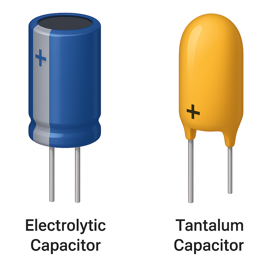
Electrolytic & Tantalum Capacitors
- The Electrolytic & Tantalum Capacitors act as large local energy reservoirs, perfect for handling slower voltage droops that occur when a major part of a chip (like a processor core) wakes up from sleep. They have much higher ESR and ESL than MLCCs, making them too slow to handle high-frequency switching noise. NOTE: These capacitors are polarized. They have a positive and negative terminal. Installing one backward will permanently damage it, often causing it to vent or burst.
So What’s the Bottom Line?
Decoupling capacitor placement isn’t about adding a few capacitors near the power rail and hoping for the best to work out. It’s about knowing what the capacitor does at the frequency your circuit operates at, and most importantly, placing it exactly where it needs to be. If you get the SRF wrong, and ignore layout, or pick the wrong dielectric, then the noise will find its way into your circuit.
I have seen designs that pass lab tests but fail in the field because the power rail couldn’t keep up when it mattered. And every single time, the fix was not just another regulator or a firmware patch; it was just using the right capacitor, in the right place, with the right specs.
If you want clean power, don’t just “add capacitors.” Understand them. Stack values that cover your full frequency range. Keep the decoupling capacitor placement close to the IC. And most importantly, treat layout like it’s part of the circuit, not an afterthought.
That’s the difference between a stable product and one that resets when the user turns on a fan.