Power electronics hobbyists and engineers struggle in choosing between SiC MOSFET vs Si IGBT. Due to an increase in industrial, energy storage, and renewable energy demands, these technologies are at the forefront of power electronics in 2025. The transition is in an active phase from traditional Si transistors to those made using wide-band gap SiC material. In this blog, we explore what SiC transistor such as SiC MOSFETs vs Si IGBTs differences are and shed light on their respective advantages. We also consider their drawbacks, and present numerous applications where each device shines (or falls short).
By the end of this blog, you should understand why silicon carbide MOSFET devices are generating so much hype. You’ll also see how SiC devices stack against traditional silicon IGBTs in real-world use.
Understanding Silicon IGBTs and Silicon Carbide MOSFETs
Both Silicon Carbide MOSFET vs Si IGBT, are switching devices that can handle varying degrees of voltage, current and operate at specified switching frequency. However, as we have seen in our detailed blog on MOSFET vs IGBT, typical MOSFETs are suitable for high-frequency applications. MSOFETs are also capable of handling low to moderate currents and voltages. On the other hand, IGBTs are better suited for high voltage, high DC, or continuous current.
The clear distinction between MOSFETs and IGBTs begins to blur when we change the construction material of MOSFETs from Si (Silicon) to SiC (Silicon Carbide).
Si IGBT
A conventional IGBT (also called a Si IGBT) has three terminals similar to the MOSFET, with different names, though. The IGBT terminals are called Gate, Collector, and Emitter as demonstrated in the following structure, and visual image of the IGBT:

Similar to the Si MOSFET, the Si IGBT is voltage-driven at the Gate, but with a defining difference that the IGBT conducts using both the minority and majority carriers in the material. Because of this bipolar conduction, the Si IGBTs turn-off slowly due to stored charge (also called the “tail current”). This tail current restricts the Si IGBT’s switching frequency, making it a good fit only for slow switching frequency applications compared to the Si MOSFETs.
SiC MOSFET
Silicon Carbide MOSFETs (SiC MOSFETs) are not drastically different from conventional Si MOSFETs in terms of their core functionality, and have the same number of functional pins: Gate, Drain, and Source. Likewise, they both are controlled using a voltage-operated insulated Gate. SiC MOSFETs are also unipolar devices that conduct using majority carriers, allowing faster switching speeds.

The SiC MOSFET operates on the same principle of conduction when the gate voltage reaches a specific threshold level. However, due to SiC material’s capabilities, the SiC MOSFET can handle much higher temperatures and voltages than the Si MOSFET. Previously, the particular reason why Si MOSFETs were dropped in favor of IGBT was the large voltage drop across MOSFET’s $R_{DS(on)}$ at a very high current. This shortcoming is remedied using SiC material for SiC MOSFET construction, which allows a similar lower voltage drop at higher currents as the traditional IGBTs. Hence, MOSFETs once again became viable option for high-power applications.
Essentially, the SiC MOSFETs merge the gate control and fast switching of traditional MOSFETs with the high-power capacity of traditional IGBTs. Effectively, SiC MOSFETs rival the traditional IGBT due to better construction material.
Si vs. SiC: Material Differences & Benefits
Previously, we have seen that the MOSFETs constructed with SiC demonstrate superior performance over the conventional Si MOSFETs. Now we delve deep into understanding why this is the case:
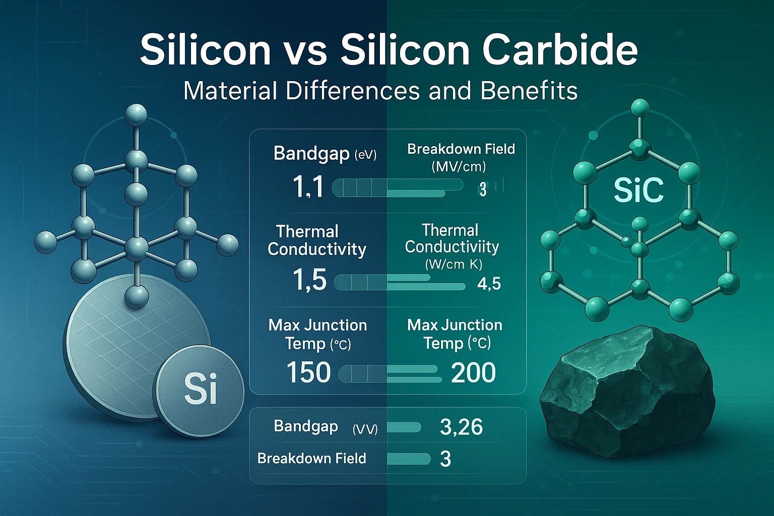
Higher Bandgap Energy
Silicon Carbide semiconductor (SiC) is a wide-bandgap energy semiconductor. Simply put, Silicon carbide can withstand much more energy the Silicon before it breaks down. In numbers, Silicon Carbide has 3.26 eV bandgap energy compared to 1.12 eV of Silicon. So, the Silicon Carbide has almost 3 times the bandgap energy that of Silicon.
The higher bandgap energy of Silicon Carbide directly translates into SiC MOSFETs’ ability to operate in higher temperatures and withstand stronger electric fields compared to silicon-based MOSFETs.

Silicon Carbide semiconductors can operate between $175 °C – 200 °C$ junction temperature, which is much more than silicon-based transistors rated for a maximum $150 °C$. The higher temperature bearing capacity enables SiC-based MOSFETs to operate at very high temperatures, such as in aerospace, automotive under the hood, and downhole drilling applications.
Higher Breakdown Electric Field
Silicon Carbide semiconductor has a much higher breakdown electric field than Silicon. In terms of numbers, the SiC material can handle 2 – 4 MV/cm electric field, which is approximately an order of magnitude more than Silicon. Engineers can manufacture thinner and more heavily doped devices using Silicon Carbide, thanks to its ability to withstand much higher voltage per centimeter than silicon.
Commercial SiC MOSFETS can operate between 1200 V – 1700 V, whereas Si MOSFETs would tap out at 900 V, and the designer had to opt for IGBT beyond 600 V applications. Effectively, designers build much sturdier and more efficient, high-voltage MOSFETs (SiC MOSFETs) using Silicon Carbide rather than with Silicon.
High Thermal Conductivity
In addition to Silicon Carbide’s ability to perform flawlessly under higher temperatures, Silicon Carbide semiconductor has superior thermal conduction (3x Si) compared to Si-based semiconductors.
Better thermal conduction means better heat dissipation and less thermal resistance. SiC’s superior thermal conduction has a direct effect on reduced thermal runaway resistance compared to equivalent Silicon devices. SiC’s better thermal performance enables designers to choose slimmer heatsinks and simpler cooling systems in condensed circuit design.
Faster Switching Speed
As we have already elaborated in detail on our blog MOSFET vs IGBT, the MOSFETs conduct through majority carriers only. Majority carrier conduction allows MOSFETs to switch faster than IGBTs’ bipolar conduction. They already have lower losses at higher temperatures.
Due to superior switching speed to IGBTs, MOSFETs offer higher PWM frequencies in applications such as DC Motor Speed Controller Circuits, effectively allowing slimmer magnetics (inductors, transformers) and capacitance, reducing the overall circuit size and weight.
From the superior properties of Silicon Carbide described above, we can see that silicon carbide semiconductor material is harder, faster, and can sustain higher temperatures optimally. However, the benefits of the SiC are not without drawbacks.
SiC’s material has higher hardness, and during its crystal stage, the early-stage crystal defects (e.g., dislocations, interface oxide issues) had made the fabrication relatively more complex and cost higher than the traditional Si processing.
Performance Comparison: SiC MOSFET vs Si IGBT
The benefits of the SiC material are described earlier. Let’s now explore how SiC MOSFETs stack against the Si IGBTs in terms of performance metrics from the designers and engineers’ perspective. The performance metrics we consider are conduction losses, thermal performance, switching speed & switching losses, gate driving requirements and control considerations.
Conduction Characteristics (On-State Losses)
As explained in our detailed blog MOSFET vs IGBT, the IGBT behaves like a diode in the on-state, with a small voltage drop plus a small resistive load. This $V_{CE(sat)}$ is 1-2 V for the rated current of many IGBTs. Until the device’s limit is almost reached, this voltage drop does not increase. A MOSFET, on the other hand, acts as a resistor. At a smaller current, it drops lower voltage. However, MOSFET linearly increases the voltage drop predictably using formulae $IR_{DS(on)}$ as the current increases. Engineers favored IGBTs over MOSFETs because, at higher currents, IGBTs maintained a lower voltage drop than MOSFETs operating under the same conditions.
When comparing SiC MOSFET vs Si IGBT, we discovered that SiC MSOFETs change this scenario drastically. SiC MSOFET can have lower $R_{DS(on)}$ despite higher voltages ranging from 1200 V to 1700 V. For example, a state-of-the-art SiC MOSFET may have only 25 mΩ on-resistance at 1200 V. This astounding feat means this SiC MOSFET can pass 50A current and still drop only around 1.25 V – a comparable number to the IGBT performance.
SiC MOSFET vs Si IGBT: Thermal Performance
The lower $R_{DS(on)}$ also has an effect on the thermal performance of the power transistor device, whether MOSFET or IGBT. At let’s say $150 °C$, the $V_{CE(sat)}$ of IGBT, and $R_{DS(on)}$ of the MOSFET rise.
In examining the SiC MOSFET vs Si IGBT, due to the better thermal performance of SiC material, the SiC MOSFETs offer outstanding low on-resistance, closing the gap in high-current use cases while retaining the low-drop advantage at higher current applications.
Switching Speed and Switching Losses
As indicated earlier, IGBTs suffer from tail current, limiting their ability to swiftly turn on or off. This is exactly where the MOSFETs in general and SiC MOSFETs in particular truly shine. A MOSFET responds almost immediately to the gate voltage compared to an IGBT’s slow turn-on and off times. Practically, SiC MOSFETs complete switching transitions in tens of nanoseconds, while IGBTs take hundreds of nanoseconds or even microseconds at similar voltage levels.
Due to fast switching speed, the SiC MOSFET has lower switching loss ($E_{on)}$ and$E_{off)}$ ) compared to an IGBT of equal rating. In an experiment to validate these statements, Toshiba took a single-phase inverter model functioning with a 1200 V Si IGBT. The same inverter was then tested with a 1200 V, 70 mΩ SiC MOSFET. At 800 V, 10 A switching, each turn-off of the SiC MOSFET had ~78% less energy loss than the IGBT the similarly rated IGBT.
The example of switching-on and switching-off loss reduction is shown in the following curves:
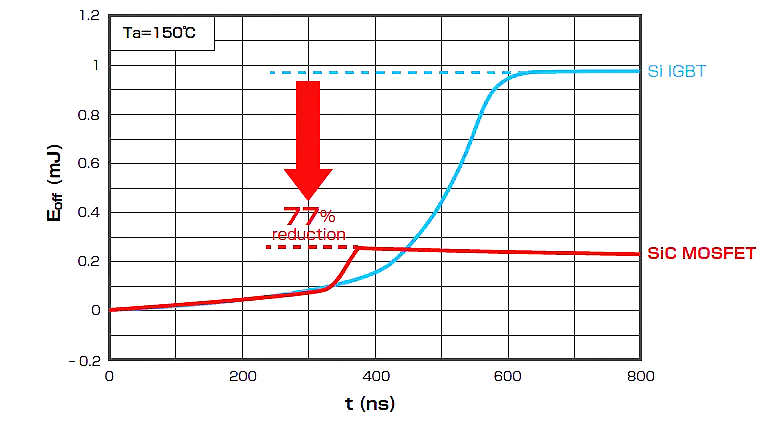
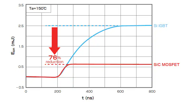
In further investigation, when an Si IGBT in this inverter was replaced with 2nd generation SiC MOSFET, the turn-on and turn-off losses were significantly reduced as demonstrated in the following table
| Device | Switching Loss | ||||
| Conduction loss | Turn-on | Turn-off | Total loss | ||
| IGBT | 4.4W | 3.1W | 6.9W | 14.4W | |
| SiC MOSFET | 4.5W (~ 2% up) | 2.5W (~ 19% down) | 1.5W (~ 78% down) | 8.5W (~ 41% down) | |
IGBTs have inherently slower switching, particularly at higher voltages of around 1200V or up, and substantial losses. In contrast, the SiC MOSFET switch is orders of magnitude faster than the Si IGBT. Also, SiC MOSFETs can do this with far less energy losses, yielding higher efficiency at any given frequency.
SiC MOSFET vs Si IGBT Gate Driving Requirements Considerations
At the control level, both Si IGBT and SiC MOSFET are voltage-controlled devices. However, the gate requirements for both devices are different, as demonstrated below:
SiC MOSFET vs Si IGBT: Gate Voltage Level
Traditional IGBTs require ~+15V at the gate to fully turn on. In adverse situations, IGBTs can also handle up to +30 V. Typically, either 0 V or a slight negative voltage (-5V) is used to turn them off. Most SiC MOSFETs, however, require slightly more voltage (+18V) to fully turn them on. SiC MOSFET also benefits from 5V to robustly turn off and avoid false turn-on due to Miller Capacitance.
There is a slight difference between the recommended +18V drive of SiC MOSFET and the device’s max allowable drive voltage (~ +20 V to +22 V), leaving little room for error. So, for SiC MSOFET, precision gate driving is crucial. You might want to protect it using Overvoltage Protection using a TVS diode.
Gate Capacitance and Drive Current
SiC MOSFETs have lower gate charge ( $Q_{g)}$) than an IGBT of the same rating. This means that the driving gate at high speed requires less driving power. However, at high frequencies, gate power can add up, with the plus side that the gate drive ICs can handle it optimally.
IGBTs, however, have higher input capacitance and require more gate drive current at a given frequency. Their gate is also intentionally driven more slowly to control $di/dt$.
SiC MOSFET vs Si IGBT: Gate Driver IC Availability
Due to the potential and interest of the industry in SiC devices, gate driver ICs for both SiC and Si devices are widely available. Especially, the SiC MOSFET gate driver has captured industry’s attention.
Many gate driver chips act as both SiC MOSFET gate driver as well as Si IGBT gate driver. Take the example of the Tamura 2DMB80407CC, which is a dual isolated driver that explicitly supports driving “IGBT or SiC MOSFET” half-bridges.
With the slight inconvenience of adjusting the gate voltage and adding a negative bias supply, driving a SiC MOSFET is not substantially different from driving an IGBT from an engineer’s and designer’s perspective.
SiC MOSFET vs Si IGBT: Use Cases in 2025
Both IGBTs and SiC MSOFETs are extensively used in power electronics. However, their specific niches are evolving as technology pushes limitations boundaries in both types of transistors. Below are some specific applications better suited for each type of switching device.
Electric Vehicle (EV) Powertrains
Fast switching frequency, high voltage and current handling, and thermal performance are the go-to issues when considering electric vehicle battery system design. Before SiC MOSFETs, most EV battery systems utilized IGBTs for their 400 V systems for motor inverters. However, the SiC MOSFETs changed the game with new possibilities without much compromise on space, quality, or cost. In 2025, new EV models (especially the ones with bigger 800 V systems) will use SiC MSOFETs based inverters. A classic example of SiC MOSFET utilization is in Tesla cars, which famously introduced SiC MOSFETs in their Model 3 cars. Tesla was the first in EV automative industry to use SiC MOSFET.
SiC MOSFETs deliver outstanding advantages that no other transistor could provide:
- High switching frequency enables smaller inverter size saving more space of bigger batter pack
- Lower inverter losses (up to 10%) providing 5-10% more driving range
- Enabling fast charging via 350 kW chargers and even more.
A McKinsey report projects over half of the EV automotives utilizing the SiC MOSFETs in their inverters by 2027. Likewise, based on evolving EV demands, the expected SiC production is also estimated to drastically rise by 2027 as shown in the image below:

Renewable Energy Inverters (Solar, Wind)
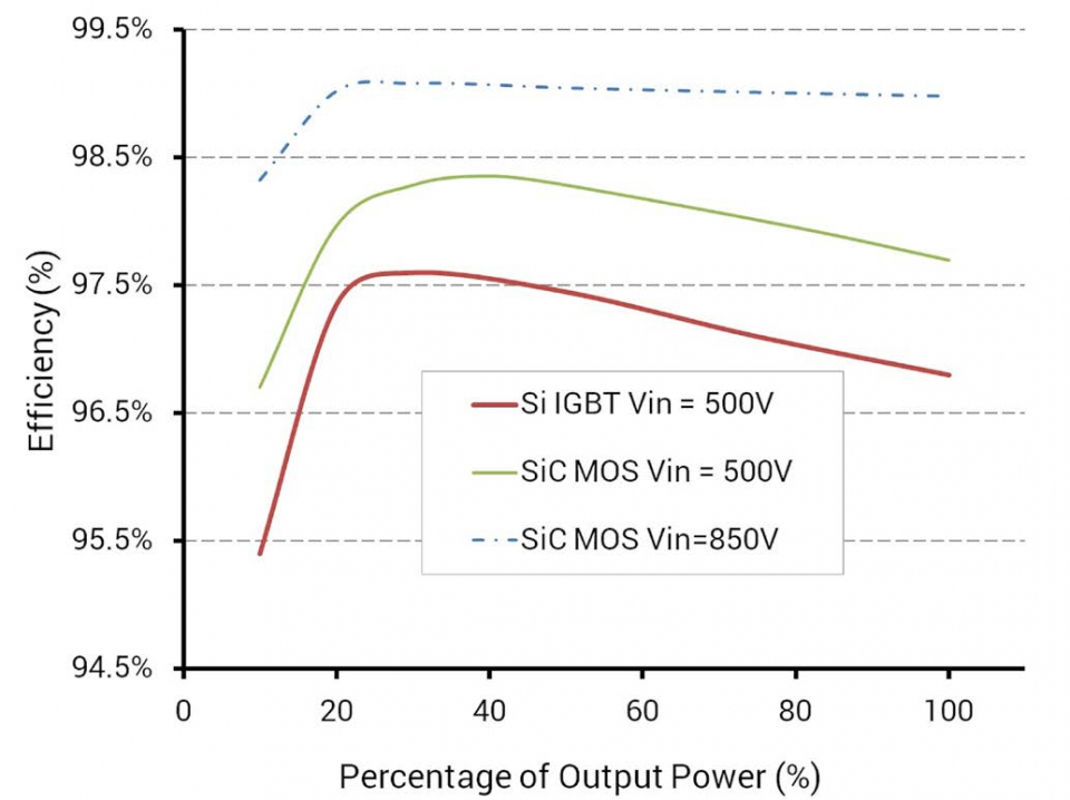
Solar farms and wind turbines use DC-AC inverters to harvest solar and wind energy from DC form to AC form. Likewise, AC energy is converted to DC for battery bank charging. Previously, the inverters of the power 50 kW- 250 kW employed IGBTs in their inverter circuit. More recently, however, SiC MOSFETs are preferred over the traditional IGBTs to substantially increase the efficiency and power density of solar inverters. As demonstrated in the following chart, the SiC MOSFET-based inverters are able to provide 1% higher efficiency at the input voltage.
The built-in, high switching frequency of SiC MOSFET allows for smaller magnetics, enabling better space and thermal management, and yielding lower eventual cost. It is crucial to mention here that the industry in renewable energy inverters has yet to see noticeable traction in SiC MOSFET adoption due to existing high-reliability and trust in IGBT-based inverter installation.
Nonetheless, as the industry aims to squeeze every bit of inverter space, thermal performance, and bigger systems, the SiC MOSFET is becoming the next big thing in power electronics.
Aerospace, Defense, and Drones
Aerospace, defense, and drone industries represent sectors where cost is not the primary concern, making SiC MOSFETs well-suited for these applications. SiC MOSFET’s superior radiation resistance (attributed to the wide bandgap) results in reduced susceptibility to radiation-induced failures—a significant advantage for space electronics and high-altitude flight systems.

Smaller hobby drones (often operating at <50 V) may use Si MOSFETs or even GaN FETs because of low voltages and existing high efficiency. However, high-power drones or eVTOL (electric helicopters/flying taxis) operating on higher voltages could substantially leverage SiC to squeeze weight in their motor controllers.
Conclusion
In 2025, power electronics applications are strongly trending towards SiC MOSFETs when efficiency, compact size, better thermals, and higher power requirements are at the forefront of device selection considerations.
Frequently Asked Questions (FAQs)
i. Why are silicon carbide semiconductor devices preferred over traditional Si devices?
Silicon Carbide semiconductor (SiC) devices are preferred over Si devices because they offer significant performance improvements. Key reasons include:
- Higher Efficiency
- Higher Voltage & Current Handling Capacity
- Faster switching (higher frequency)
- High temperature operation
ii. What is the difference between SiC MOSFET vs Si IGBT?
The difference boils down to both the material and the device type:
- Material: A SiC MOSFET is made of Silicon Carbide, whereas a Si IGBT is made of plain Silicon.
- Device type: A MOSFET (Si or SiC) is a unipolar field-effect transistor and conducts via majority carriers (electrons in an N-channel device)
An IGBT is a bipolar device with both minority and majority carriers conducting the current.
iii. What is the highest gate threshold voltage of a SiC MOSFET?
For the highest voltage, currently up to ~3.3 kV in mainstream products, 6.5 kV in emerging products, and >10 kV in lab demonstrated products, are available in SiC MOSFET technology.
For gate threshold voltage, SiC MOSFETs need around +15 V to +18 V gate drive to reach the specified on-resistance.
iv. What are the disadvantages or problems with SiC MOSFETs?
Main disadvantages of SiC MOSFETs include:
- Limited Availability and Supply Delays
- Higher Cost
- Limited short-circuit withstand (SCWT)
- Careful EMI and $dv/dt$ management
v. How do you drive a SiC MOSFET vs Si IGBT (i.e., how to properly turn them on/off)?
Driving a SiC MOSFET is similar in concept to driving an IGBT or standard MOSFET.
vi. Are SiC MOSFETs susceptible to radiation?
SiC MOSFETs are less prone to certain types of radiation than Si devices. Their wide bandgap makes them much more resistant to failures from cosmic rays or high-altitude neutrons. For example, Wolfspeed’s Gen4 SiC MOSFETs demonstrate up to 100× better cosmic-ray failure rates than earlier generations.
vii. Is GaN better than SiC?
It depends on the application and what your crucial considerations are:
- Switching speed and frequency: GaN devices are superior
- Voltage Range: SiC devices have better options than GaN devices for >600V applications
- Current Handling: SiC devices can handle much more current (100 A and more) than GaN devices (<50 A at best)
- Cost: SiC has the advantage of more established high-voltage production and larger devices, effectively decreasing the cost
viii. What are the benefits of a “SiC IGBT”? (Or, does a SiC IGBT exist?)?
There really aren’t commercial “SiC IGBTs” in use. However, a theoretical SiC IGBT would have some advantages over a Si IGBT (higher voltage, higher temperature, etc., from the SiC material).
ix. Summarize the differences between SiC MOSFET vs Si IGBT
Here is the quick reference table of SiC MOSFET vs Si IGBT (2025)
| Feature | Si IGBT | SiC MOSFET |
|---|---|---|
| Max Rated Voltage | 650V–6.5kV | 650V–3.3kV (6.5kV in R&D) |
| Max Current (Discrete) | 40–100A | 40–100A |
| $R_{DS(on)}/ V_{CE(sat)}$ | 1.5–2V | 25–80 mΩ @1200V |
| Switching Frequency | <20kHz | 20kHz–500kHz+ |
| Junction Temp $T_{J}$ | 150°C | 175–200°C |
| Cost | Lower | Higher, but falling |
| Short Circuit Withstand | 5–10µs | 2–5µs (latest Gen) |
| EMI Sensitivity | Moderate | High (needs care) |