A small relay can stop a major vehicle system from working. If the fuel pump, cooling fan, horn, headlight, or AC compressor suddenly stops responding, the relay is often one of the first parts worth checking. An automotive relay tester helps you confirm whether the relay is working before you replace parts or start chasing wiring faults.
Many car electrical problems trace back to these small electromechanical switches that control high-current devices throughout your vehicle.
While relays are relatively inexpensive, diagnosing relay problems without the right tools can lead to unnecessary part replacements, wasted time, and mounting frustration.
This guide covers everything you need to know about automotive relay testers: what they are, how they work, when to use them, and how to test automotive relays with or without specialized equipment.
What Is an Automotive Relay?
Before diving into testing methods, it’s important to understand what an automotive relay actually does.
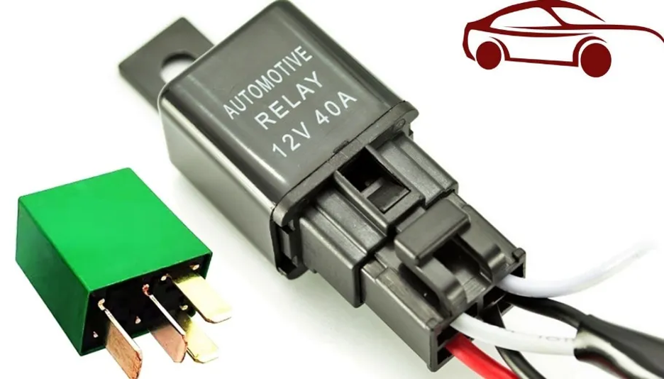
A relay is essentially an electrically controlled switch. It allows a low-current control circuit to switch a higher-current load without forcing that heavy current through sensitive switches, control modules, or thin wiring.
Here’s why relays matter: imagine your fuel pump draws 10 amps of current. Without a relay, that current would have to flow through your ignition switch, the wiring harness, and possibly through an electronic control module.
That’s a recipe for burnt contacts, melted wiring, and failed components. Instead, a relay does the heavy lifting.
A small control signal (usually less than 200 milliamps) energizes the relay coil, which then closes internal contacts capable of handling the fuel pump’s full current demand.
Most automotive relays are electromechanical devices. Inside the plastic housing, you’ll find a coil of wire wrapped around an iron core and a set of movable contacts.
When current flows through the coil, it creates a magnetic field that pulls the contacts closed, completing the high-current circuit. When the control signal stops, a spring returns the contacts to their resting position.
Common vehicle systems that depend on relays include:
- Fuel pumps
- Cooling fans
- Headlights and fog lights
- Horn circuits
- Starter motor circuits
- Air conditioning compressor clutches
- Power window motors
- Wiper motors
- Heated seat elements
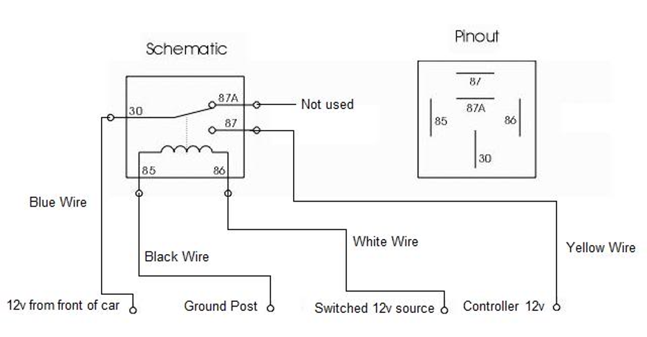
Automotive Relay Pinout
Understanding relay pin numbering is essential for testing. Most automotive relays follow a standard numbering system established by the International Organization for Standardization (ISO).
Here’s what each pin does:
| Pin | Function |
| 85 | Coil terminal (ground side) |
| 86 | Coil terminal (power side) |
| 30 | Common power terminal (battery feed) |
| 87 | Normally open output (energized contact) |
| 87a | Normally closed output (found on some 5-pin relays) |
In a typical 4-pin relay setup, pin 30 receives battery voltage, pins 85 and 86 control the coil, and pin 87 sends power to the controlled device when the relay activates.
A 5-pin relay adds pin 87a, which is connected to pin 30 when the relay is at rest and disconnects when the relay energizes—useful for applications that need a normally closed contact.
This standardized numbering system makes relay testing more consistent across different vehicle makes and models.
When you understand these pin functions, you can test virtually any automotive relay using the same basic approach.
What Is an Automotive Relay Tester?
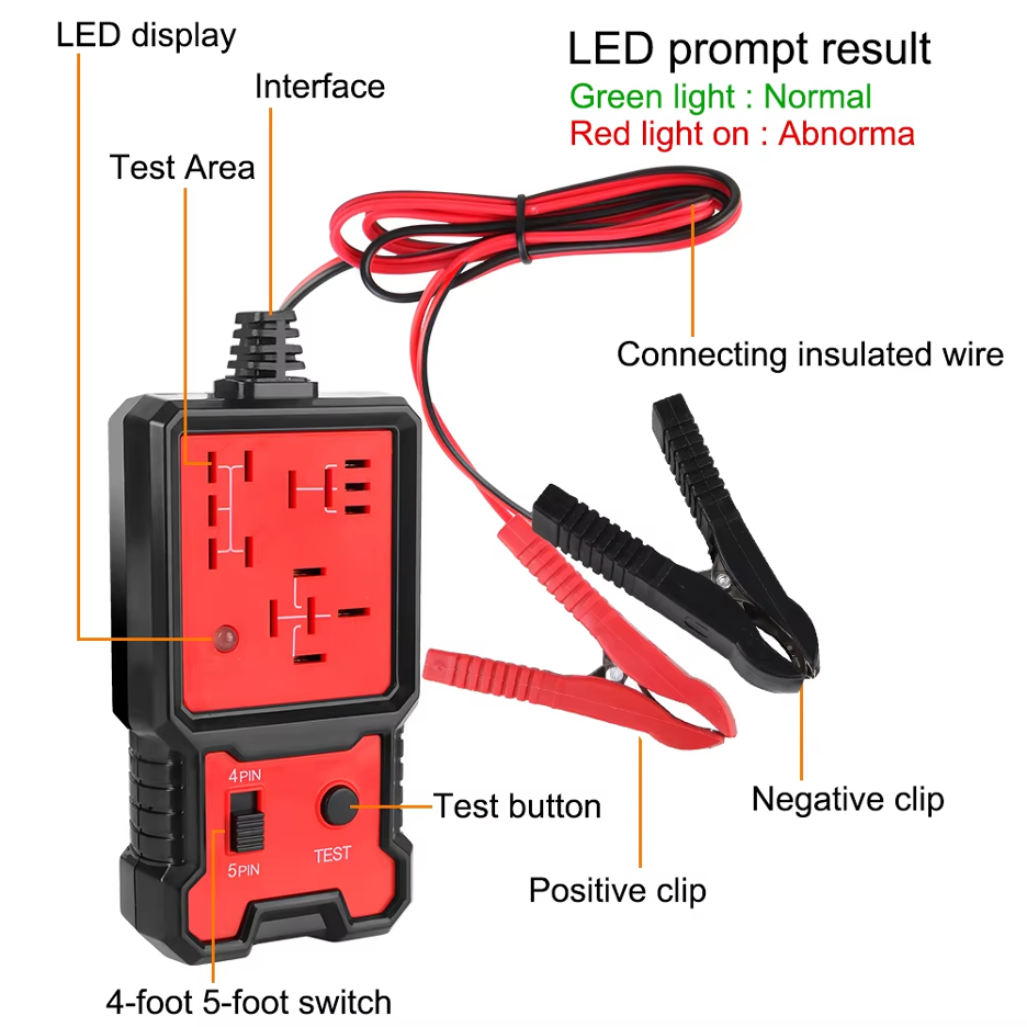
An automotive relay tester is a diagnostic tool specifically designed to check whether a vehicle relay activates, switches, and maintains contact correctly.
Instead of manually applying voltage with jumper wires and checking continuity with separate meter leads, the tester powers the relay coil and automatically monitors the switching behavior.
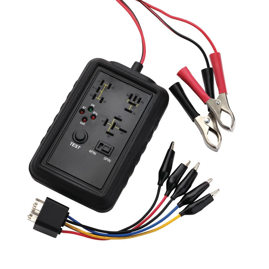
These testers work off the vehicle, which means you pull the relay from its socket and insert it into the tester.
Most relay testers connect directly to the vehicle battery for power, though some professional models include their own power supply.
Here’s what sets a good automotive relay tester apart:
- Voltage Compatibility: Basic testers work only with 12-volt systems common in passenger cars. More versatile models support both 12V and 24V systems.
- Pin Configuration Support: Many testers accommodate both 4-pin and 5-pin relays. Some models feature a selector switch that lets you choose which configuration you’re testing.
- Cycling Capability: Better relay testers don’t just activate the relay once—they cycle it multiple times during a single test.
- Load Testing: Premium testers apply actual current through the switched contacts, not just voltage. This loaded contact testing reveals high-resistance problems that can cause relays to fail under real-world operating conditions.
- Visual Feedback: Most testers use LED indicators—typically green for pass and red for fail. Some advanced models display diagnostic trouble codes using flash patterns to indicate specific failure modes like open coil, shorted contacts, or excessive contact resistance.
The beauty of an auto relay tester is its simplicity. You don’t need to reference wiring diagrams, probe terminals with a multimeter, or jury-rig a test setup.
Insert the relay, press a button, and watch for the indicator.
How Does an Automotive Relay Tester Work?
An automotive relay tester performs a systematic check of the relay’s key functions. While different models vary in sophistication, most testers evaluate relays using three core tests:
1. Coil Activation Test
The tester first checks whether the relay coil functions properly. It applies the appropriate voltage (12V or 24V, depending on the setting) across the coil terminals—pins 85 and 86.
A healthy coil has a specific resistance, typically ranging from 40 to 120 ohms depending on relay design.
If the coil is open (broken wire inside), it presents infinite resistance and won’t create the magnetic field needed to close the contacts.
If it’s shorted (insulation breakdown between windings), it draws excessive current and may blow fuses. The tester detects both conditions.
When the coil energizes properly, you should hear an audible click as the electromagnetic field pulls the armature and closes the internal contacts. The tester monitors whether this activation occurs consistently.
2. Contact Switching Test
Next, the tester verifies that the internal switching contacts actually change state when the coil energizes.
For a 4-pin relay, this means checking whether terminal 30 (common) connects to terminal 87 (normally open output) when power is applied to the coil.
The tester does this by monitoring continuity between these terminals while cycling the relay. When the relay is at rest, there should be no connection between 30 and 87.
When energized, continuity should be established immediately.
For 5-pin relays, the tester may also verify the relationship between pins 30, 87, and 87a. In the resting state, pins 30 and 87a should show continuity.
When energized, that connection should break and continuity should appear between pins 30 and 87 instead.
3. Repeated Cycling Test
Here’s where better automotive relay testers distinguish themselves. Instead of energizing the relay once and calling it good, quality testers cycle the relay multiple times—sometimes dozens of times in rapid succession.
Why does this matter? Because relay failures aren’t always consistent. A relay might work perfectly on the first try but fail on the tenth activation. Contacts might stick together occasionally. The armature might return slowly due to weak spring tension. Rapid cycling stresses the relay and exposes weaknesses that single-cycle testing would miss.
Some advanced testers also incorporate loaded contact testing, which means they actually pass current through the closed contacts while measuring voltage drop.
A relay might show continuity between terminals 30 and 87 when energized, but if the contacts have high resistance, voltage drop under load will reveal the problem.
This simulates real-world conditions more accurately than simple continuity testing.
The combination of these three tests gives you confidence in the results. When a relay passes all three checks, you can trust that it’s functioning properly.
When it fails any check, you have a clear indication that replacement is necessary.
How to Use an Automotive Relay Tester Step by Step
Testing relays becomes straightforward once you understand the process. You can follow these steps for accurate results:
Step 1: Identify the Relay
Before you can test a relay, you need to find it. Most vehicles have multiple relay locations:
- Under-hood fuse box: Usually near the battery, containing high-current relays for the starter, fuel pump, cooling fans, and headlights
- Interior fuse panel: Typically under the dashboard on the driver’s side, housing relays for power windows, wipers, and interior accessories
- Auxiliary relay boxes: Some vehicles have additional relay boxes in the trunk, under seats, or in specific system locations
Check your vehicle’s owner’s manual or service manual for relay locations. The fuse box cover often includes a diagram showing which relay controls which circuit.
Step 2: Remove the Relay Safely
Before removing any relay, ensure the ignition is off and the circuit is inactive. Pulling a relay while current is flowing through it can cause arcing and damage the contacts.
Grasp the relay firmly and pull straight up. Most relays simply plug into a socket. Some have a small tab you press to release them.
Avoid rocking the relay side to side during removal, as this can bend socket terminals and create future connection problems.
Inspect the relay socket while the relay is out. Look for:
- Burned or melted terminals
- Corrosion or green deposits
- Bent socket pins
- Evidence of overheating
If the socket shows damage, address that issue before testing the relay. A bad socket can make a good relay appear faulty.
Step 3: Match the Relay Type
Examine the relay to determine its configuration. Count the terminals. Most automotive relays have either 4 or 5 pins.
The relay housing usually displays the pin diagram showing terminal numbers and their functions.
Verify that your relay tester supports the relay type you’re testing. If your tester has a selector switch for 4-pin or 5-pin operation, set it correctly.
Using the wrong setting can produce inaccurate results or fail to test all relay functions.
Also note the voltage rating printed on the relay. Most passenger vehicle relays operate at 12 volts, but some heavy-duty trucks, buses, and equipment use 24-volt systems.
Make sure your tester supports the relay’s voltage rating.
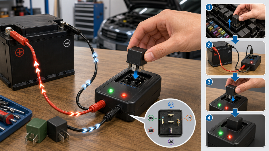
Step 4: Connect the Tester to Power
Most automotive relay testers draw power from the vehicle battery. This approach is convenient because the battery is already the correct voltage for the relay.
Connect the tester’s power leads to the battery, observing proper polarity:
- Red clip to positive (+) terminal
- Black clip to negative (-) terminal or a clean ground point on the engine block
Ensure the clips make solid contact. Loose or corroded connections can cause voltage drop that affects test results. Some testers include a power indicator light that confirms good battery connection.
Step 5: Insert the Relay into the Tester
Align the relay pins with the socket on the tester. Most testers use a socket that matches standard automotive relay terminal layouts, but take a moment to verify proper alignment before inserting the relay.
Push the relay firmly into the socket until it seats completely. A partially inserted relay won’t make good contact and will fail the test even if it’s functional.
Step 6: Run the Test
Operating the tester varies by model. Some testers work with a simple press-and-hold button—hold the button down and the tester energizes the relay and checks switching operation.
Release the button and the relay should de-energize.
Other testers use automatic cycling. Press the test button once and the tester runs through a programmed sequence, energizing and de-energizing the relay multiple times while monitoring performance.
During the test, you should hear the relay clicking as the tester cycles it. This clicking confirms that the coil is pulling the contacts, though as noted earlier, clicking alone doesn’t guarantee the relay is good.
Step 7: Read the Result
Pay attention to the tester’s indicator lights or display:
- Green Light or PASS Indication: The relay passed all tests. The coil energizes correctly, contacts switch properly, and the relay cycled consistently. You can reinstall the relay with confidence.
- Red Light or FAIL Indication: The relay failed one or more tests. The coil might be open or shorted, contacts may not be switching, or the relay showed inconsistent operation during cycling.
- Flashing Code Pattern: Some diagnostic relay testers use flash codes to provide more specific information about the failure mode. For example:
- Fast red flashes might indicate an open coil
- Slow red flashes might indicate contact failure
- Alternating red/green might indicate intermittent operation
Consult your tester’s instruction manual to interpret any diagnostic codes it displays.
How to Test an Automotive Relay Without a Relay Tester
While an automotive relay tester is the fastest and easiest method, you can absolutely test relays without one.
These manual testing methods require more time and a basic understanding of electrical principles, but they’re effective when you don’t have access to specialized equipment.
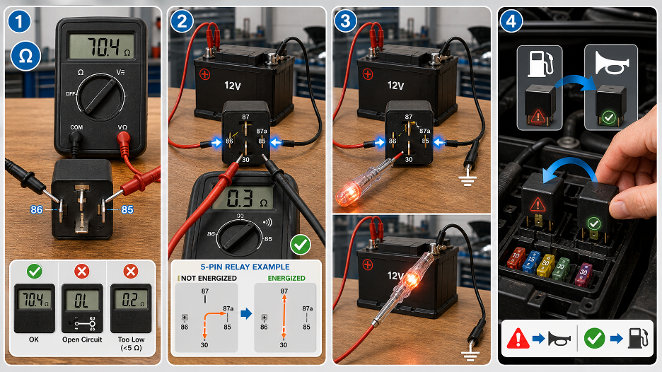
Method 1: Test Coil Resistance with a Multimeter
This method checks whether the relay coil is intact and within specifications.
Equipment needed: Digital multimeter
Procedure:
- Set your multimeter to the resistance (ohms) setting, typically 200 ohms or 2K ohms range
- Touch one meter probe to pin 85 and the other to pin 86—the relay’s coil terminals
- Read the resistance value displayed
Interpreting results:
- A typical automotive relay coil measures between 40 and 120 ohms, though this varies by relay design
- “OL” (overload) or infinite resistance indicates an open coil—the internal wire is broken
- Very low resistance (under 5 ohms) might indicate a shorted coil
- If possible, compare your reading to the manufacturer’s specifications or to a known-good relay of the same type
Method 2: Test Contact Continuity
This method verifies that the relay contacts actually close when the coil is energized.
Equipment needed: Digital multimeter, 12V battery or power supply, jumper wires
Procedure:
- Set your multimeter to continuity or low-resistance mode
- For a normally open relay (most common), place meter probes on terminals 30 and 87
- With the relay unpowered, you should read infinite resistance (open circuit) or no continuity
- Using jumper wires, connect a 12V battery to terminals 85 and 86 (polarity doesn’t usually matter for testing, though 86 is typically positive)
- The relay should click audibly as the coil energizes
- The multimeter should now show continuity or very low resistance (under 1 ohm) between terminals 30 and 87
- Disconnect the battery and verify that continuity disappears as the relay de-energizes
For 5-pin relays with normally closed contacts:
- Check continuity between terminals 30 and 87a with the relay unpowered—should show continuity
- Energize the coil and verify that continuity breaks between 30 and 87a
- Simultaneously verify that continuity appears between 30 and 87
Method 3: Test with a Battery and Test Light
This field method doesn’t require a multimeter.
Equipment needed: 12V battery, automotive test light, jumper wires
Procedure:
- Connect jumper wires from a 12V battery to terminals 85 and 86 to energize the coil
- Listen for the click, confirming the relay activates
- Connect one end of your test light to terminal 30
- Ground the other end of the test light or connect it to the battery negative
- The test light should illuminate when terminal 30 receives power
- Touch the test light probe to terminal 87
- With the coil energized, the test light should illuminate if contacts are closed
- De-energize the coil and verify the test light goes out
Note: This method is quick for basic go/no-go testing but provides no resistance measurements.
Method 4: Swap with an Identical Relay
Sometimes the fastest diagnostic method is simply swapping parts.
Procedure:
- Locate another relay in your vehicle with the same part number and pin configuration
- Choose a relay from a non-critical circuit—for example, if testing a fuel pump relay, swap it with the horn relay
- Install the suspected bad relay in the non-critical circuit
- Install the known-good relay in the problem circuit
- Test both circuits
Interpreting results:
- If the problem moves to the non-critical circuit, the relay is bad
- If the problem stays with the original circuit, the relay is likely good and the fault is in the circuit wiring, fuse, or controlled component
Automotive Relay Tester vs Multimeter: Which Should You Use?
Both tools serve important diagnostic functions, but they excel in different scenarios. Understanding when to use each helps you diagnose problems efficiently.
| Tool | Best For | Limitation |
| Automotive relay tester | Fast go/no-go testing, 4-pin/5-pin relay checks, repeated cycling, loaded contact testing, quick decision making | Does not diagnose the full vehicle circuit, won’t measure exact resistance values, limited to relay testing only |
| Multimeter | Resistance measurements, continuity checks, voltage drop testing, socket power verification, precise electrical values | Slower relay testing process, requires more technical knowledge, manual setup for each test |
| Test light | Quick power and ground checks, basic circuit tracing | Less precise than multimeter, cannot measure resistance or exact voltage |
| Relay swap | Fastest field check when identical relay available | Only works if you have a matching spare relay, doesn’t provide root cause information |
When to use a relay tester:
- You need quick confirmation whether a relay is good or bad
- You’re testing multiple relays during a diagnostic session
- The symptom strongly suggests relay failure
- You want to check for intermittent relay problems
- You need loaded contact testing to verify real-world performance
When to use a multimeter:
- The relay tests good but the circuit still doesn’t work
- You need to check socket power and ground
- You want precise coil resistance measurements
- You’re testing voltage drop under load
- You’re diagnosing wiring problems between components
- You need to verify control signal voltage from an ECU or switch
The best approach: Use both tools together. Start with a relay tester for quick confirmation of relay condition.
If the relay passes but the circuit doesn’t work, switch to a multimeter for deeper circuit diagnosis. This combination covers both component-level and system-level troubleshooting.
What to Look for When Choosing an Automotive Relay Tester
Selecting the right relay tester depends on your needs, but certain features separate good testers from great ones.
Voltage Compatibility: 12V or 12V/24V
For most DIYers: A 12V tester handles all passenger cars, light trucks, SUVs, and motorcycles. If you only work on your personal vehicles, 12V capability is sufficient.
Most standard automotive applications use12V relays like the Panasonic CM1-P-12V or similar configurations.
For professionals and enthusiasts with diverse vehicles: Choose 12V/24V capability. This accommodates heavy-duty trucks, commercial vehicles, buses, agricultural equipment, industrial machinery, and marine applications.
For 24V systems, relays such as the Panasonic CB1F-T-D-P-24V are commonly used in commercial and industrial applications. The versatility justifies the modest price increase.
Pin Configuration Support
Look for explicit 4-pin and 5-pin support with a clear selector switch. Some testers claim to handle both but lack proper switching logic for normally closed contacts on 5-pin relays.
Verify that the tester actually tests pin 87a functionality, not just pins 30, 87, 85, and 86.
Pass/Fail Display Clarity
LED indicators should be bright, clearly labeled, and easily visible in various lighting conditions. Green typically indicates pass, red indicates fail. Some testers add yellow or amber for warnings or intermediate conditions.
Avoid testers with tiny LEDs that are hard to see in bright sunlight or dim garage lighting. The display should give you instant, unambiguous feedback.
Relay Cycling Capability
Better automotive relay testers cycle the relay multiple times during each test. Look for specifications mentioning:
- Number of test cycles (10, 20, or more activations)
- Cycling speed
- Intermittent fault detection
Cycling separates consistent relays from those that fail occasionally—a critical distinction for automotive reliability.
Loaded Contact Testing
This feature is often overlooked but extremely valuable. A loaded contact test applies actual current through the relay contacts while measuring voltage drop.
Why this matters: Relay contacts can show continuity yet have excessive resistance due to pitting, oxidation, or carbon deposits. Under load, this resistance causes voltage drop. A fuel pump might receive 9 volts instead of 12, reducing pressure. A fan might spin too slowly. Loaded testing catches these problems that simple continuity testing misses.
Look for testers that specify load testing capability and, ideally, the current level applied during testing.
Diagnostic Trouble Codes
Advanced testers use flash patterns or multiple LEDs to indicate specific failure modes:
- Open coil
- Shorted coil
- Normally open contact failure
- Normally closed contact failure
- Intermittent operation
- High contact resistance
This diagnostic capability speeds troubleshooting by telling you not just that the relay failed, but why it failed.
Battery Connection Quality
The tester connects to your vehicle battery, so connection quality matters. Look for:
- Heavy-duty battery clips with strong springs
- Wide, serrated jaws that grip terminals securely
- Color-coded leads (red for positive, black for negative)
- Adequate lead length (at least 18-24 inches) to reach from battery to comfortable working position
- Protective boot around clip jaws to prevent accidental shorts
Poor battery clips cause voltage drop that affects test accuracy and can lead to false failures on good relays.
Build Quality and Durability
Professional-grade testers feature:
- Robust housing that withstands drops and impacts
- Sealed or protected circuitry to resist moisture and contaminants
- Quality relay socket that maintains proper contact after hundreds of insertions
- Strain relief on power leads
- Chemical-resistant exterior for garage environments
If you’re testing relays regularly, build quality becomes more important than initial cost savings.
Clear Instructions and Pin Diagrams
The tester should include:
- Printed instructions or a reference card
- Pin number diagram showing 4-pin and 5-pin layouts
- Troubleshooting guide for interpreting results
- Safety warnings
Even experienced technicians benefit from a quick reference that eliminates guesswork.
Price vs. Value Consideration
Entry-level relay testers start around $15-30 and provide basic pass/fail testing. Mid-range models ($40-80) add features like 12V/24V support, cycling, and better build quality. Professional diagnostic testers ($100+) include load testing, flash codes, and comprehensive relay analysis.
The bottom line: Don’t buy solely on price. A $20 tester that only confirms whether a relay clicks doesn’t deliver much value beyond what you can do with a battery and test light. A better automotive relay tester that checks both the coil and the switched contacts under load provides diagnostic information worth the investment.
For DIY users testing relays occasionally: a mid-range tester ($40-60) with 12V/24V support, 4/5-pin capability, and basic cycling offers the best value.
For professional technicians: invest in a diagnostic-level tester with load testing and flash codes. The time saved and diagnostic accuracy gained quickly justify the cost.
Automotive Relay Tester Applications
Relay testers find use across a wide range of automotive and vehicle-related industries.
Understanding where these tools are valuable helps appreciate their importance beyond simple relay diagnosis.
Car Repair and Diagnostics
Professional automotive repair shops use relay testers daily.
When diagnosing no-start conditions, cooling system problems, lighting failures, or accessory issues, relay testing often provides quick answers that save diagnostic time and prevent unnecessary parts replacement.
DIY Vehicle Maintenance
Home mechanics and car enthusiasts benefit from relay testers when troubleshooting their own vehicles. The tools are affordable enough for home use but professional enough to provide reliable results.
Many DIYers consider a relay tester essential diagnostic equipment alongside multimeters and scan tools.
Fleet Maintenance
Companies operating vehicle fleets—delivery services, taxi companies, rental car agencies—maintain multiple vehicles with similar electrical systems.
A relay tester helps fleet technicians quickly identify failed relays across many vehicles, reducing downtime and repair costs.
Truck and Bus Electrical Systems
Heavy-duty commercial vehicles rely on numerous relays to control lighting, climate systems, auxiliary equipment, and safety systems.
Technicians servicing these vehicles need 12V/24V relay testers capable of handling the higher-current relays used in commercial applications.
Agricultural Machinery
Tractors, combines, irrigation equipment, and other agricultural machines use relay-controlled systems extensively.
Field repairs often require quick relay checks to get equipment operational during critical planting or harvest seasons. A portable relay tester is invaluable in these situations.
Industrial Vehicles
Forklifts, warehouse equipment, construction machinery, and industrial vehicles incorporate relays in their control systems.
Maintenance technicians use relay testers to diagnose electrical problems that could halt production or create safety hazards.
Motorcycle and ATV Repair
Smaller vehicles like motorcycles, ATVs, UTVs, and personal watercraft use automotive-style relays in their electrical systems.
Relay testers designed for 12V systems work perfectly for these applications.
Marine 12V/24V Systems
Boats and marine equipment incorporate relay-controlled systems for bilge pumps, lighting, windlasses, and auxiliary equipment.
Marine technicians need relay testers that can handle both 12V and 24V systems common in marine applications.
Workshop Electrical Troubleshooting
Training facilities, vocational schools, and technical colleges use relay testers to teach electrical diagnostic procedures. Students learn relay fundamentals and testing techniques using the same tools they’ll encounter in professional environments.
Mobile Diagnostic Services
Technicians who provide mobile diagnostic and repair services need portable, battery-powered tools. A relay tester connects directly to the customer’s vehicle battery and provides quick relay verification without requiring shop equipment or power sources.
The versatility of automotive relay testers across these applications demonstrates their value as diagnostic tools.
Whether you work on a single vehicle in your garage or service hundreds of vehicles professionally, relay testing capability streamlines electrical diagnosis.
Final Thoughts
An automotive relay tester is one of the simplest ways to remove guesswork from vehicle electrical diagnosis. It helps you check whether the relay coil activates, whether the contacts switch correctly, and whether the relay can perform consistently through repeated cycles.
However, relay testing should not stop at a pass or fail light. A good relay can still sit in a damaged socket, lose voltage through corroded terminals, or fail to operate because the control signal, fuse, ground, wiring, or load has a separate fault.
That is why the best approach combines a relay tester with basic multimeter checks and a clear understanding of the relay’s pin layout.
If a relay does fail, choose the replacement carefully. Match the original voltage, contact rating, terminal configuration, and relay function before installing a new part.
For automotive switching applications, Flywing Tech offers a dedicated range of automotive relays, including 12V and 24V options from manufacturers such as Panasonic Electric Works and TE Connectivity.
Whether you are troubleshooting a fuel pump, cooling fan, horn, headlight, starter circuit, or auxiliary system, the right testing process can save time, reduce unnecessary part replacement, and help you repair the actual fault instead of guessing.
Frequently Asked Questions
What does an automotive relay tester do?
An automotive relay tester checks whether a relay activates and switches correctly. Most testers show a simple pass or fail result using LED indicators.
How do you test an automotive relay?
You can test an automotive relay with a relay tester, multimeter, battery, or test light. The fastest method is to insert the relay into a tester and run the test cycle.
Can a relay click and still be bad?
Yes. A click only means the coil is moving the internal contact. The contacts may still be burnt, pitted, or too weak to carry current properly.
What pins do you test on an automotive relay?
Pins 85 and 86 are usually the coil terminals. Pin 30 is the common power terminal, pin 87 is normally open, and pin 87a is used on some 5-pin relays.
Is a relay tester better than a multimeter?
A relay tester is faster for quick pass/fail checks. A multimeter is better for deeper testing, such as checking voltage, resistance, ground, and circuit faults.
Can I test a 5-pin relay with a 4-pin tester?
Only if the tester supports 5-pin relays. A 4-pin-only tester may not check the normally closed contact on pin 87a.
Why does my relay test good but the component still does not work?
The fault may be in the fuse, relay socket, wiring, ground, control signal, or the component itself. A relay tester checks the relay, not the full circuit.
Do automotive relay testers work on 24V systems?
Some do, but not all. Check whether the tester supports 12V only or both 12V and 24V systems before using it.
How many times should a relay be cycled during testing?
Many quality testers cycle the relay multiple times to catch intermittent faults. The exact number depends on the tester model.
What is loaded relay testing?
Loaded testing checks whether relay contacts can carry current under real operating conditions. It is more useful than a simple continuity test because it can reveal weak or high-resistance contacts.

COMMENTS