Introduction
The MCP3008 ADC IC is a game-changer for electronics enthusiasts looking to bridge the gap between analog and digital worlds in their Raspberry Pi projects. This inexpensive, 8-channel, 10-bit analog-to-digital converter (ADC) is a product of Microchip Technology, and is a great choice for hobbyists and makers based in the USA to connect an analog sensor–a temperature sensor, light sensor, or pressure sensor, for example–to a digital system.
The MCP3008 is a great choice whether you are using it as part of a smart home system, robotics prototype, or an environmental monitoring project. The product is tested to be reliable and easy to use and is typically priced under $5 from reputable USA electronics suppliers (e.g., FlyWing-Tech).
What makes the MCP3008 so popular? The Raspberry Pi is a popular platform for hobbyists, with one caveat: it doesn’t include an embedded ADC, which makes it harder to process analog signals directly. The MCP3008 is a great, easy-to-use solution sitting on an SPI interface that brings high levels of accuracy and versatility, making it a solid choice for your project that needs good analog-to-digital conversion.
In this comprehensive guide, we will discuss the MCP3008 key features, we will review the datasheet for important information, step you through interfacing the MCP3008 with a Raspberry Pi, report back from real-world case studies we have worked through, and answer frequently asked questions to help you get started on your project, and help you jump in even if you are unfamiliar with the parts involved.

What Comes Next:
Discover details about the MCP3008, including how it works, its specifications, and how to download its datasheet, as well as how to hook it up to your Raspberry Pi for the acquisition of analog data. This is a guide meant for a USA audience, consisting of age-appropriate suggestions and resources from reliable suppliers and communities, for either the beginner or experienced maker.
What is the MCP3008 ADC IC?
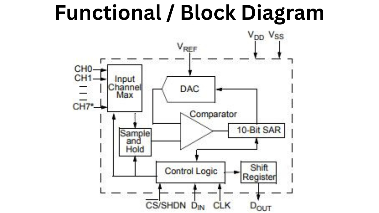
Overview and Basic Functionality
The MCP3008 ADC IC is an 8-channel, 10-bit successive approximation analog-to-digital converter (ADC) from Microchip Technology. That is used to convert analog signals into digital data for microcontrollers such as the Raspberry Pi. It is a very popular component for electronics hobbyists and makers site wide in the USA, who want to use analog sensors that measure things such as temperature, light, or potentiometers connected to a computer.
The MCP3008 uses a Serial Peripheral Interface (SPI) to communicate. So, it is easy to incorporate with the Raspberry Pi and other related microcontrollers. The basic function of the MCP3008 is that it samples analog inputs across eight channels and returns digital outputs as 10 bit digital values suitable for data acquisition in embryonic projects such as Internet of Things (IOT) devices, robotics, and environment monitoring.
This versatility and cost effectiveness (often priced for less than $5 from distributors such as FlyWing-Tech) contributes to the MCP3008 being a primary component of many maker projects and projects generally.
Key Specifications and Pinout
The MCP3008 has some really cool specs that work for all sorts of projects. It gives you a 10-bit resolution, so you get up to 1024 levels of precision. It can sample at up to 200 kilosamples per second (ksps) when you’re using 5V. Plus, it doesn’t guzzle power, usually just 120 µA while it’s running, which is perfect for energy-saving projects.
It runs on a voltage range of 2.7V to 5.5V, so it plays nicely with both 3.3V and 5V systems like the Raspberry Pi. The MCP3008 also comes with eight analog input channels (CH0-CH7). And you can set them up for single-ended or differential measurements. Giving you a lot of flexibility for different sensor setups.
The MCP3008 pinout consists of 16 pins, including:
- CH0-CH7: Eight analog input channels for connecting sensors.
- VDD: Power supply (2.7V-5.5V).
- VREF: Reference voltage for ADC conversions.
- AGND/DGND: Analog and digital ground pins for noise reduction.
- CLK, DOUT, DIN, CS: SPI interface pins for clock, data output, data input, and chip select, respectively.
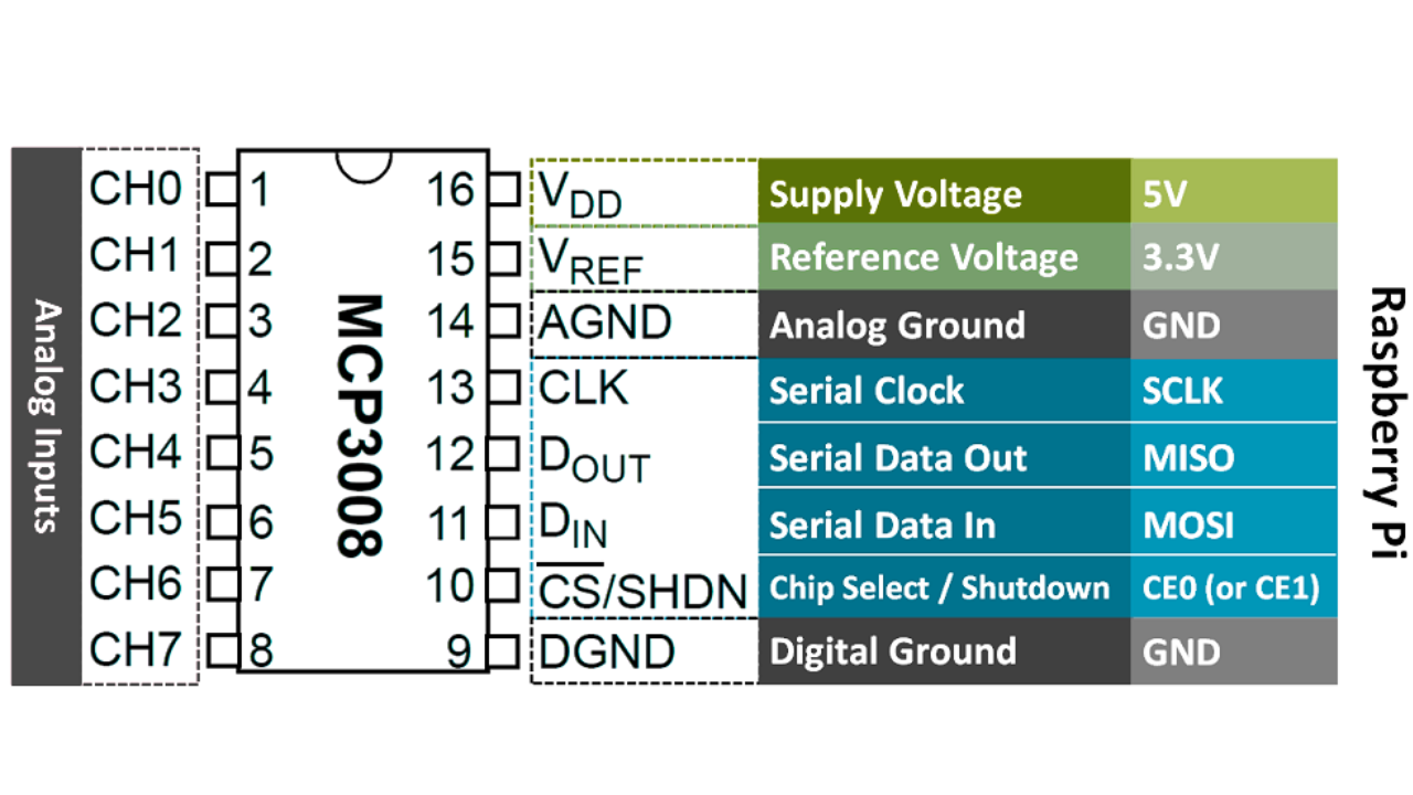
This pin layout allows easy interfacing with Raspberry Pi GPIO pins. It helps to make it available for USA-based hobbyists who create homebrew projects. For a picture reference point, refer to the datasheet or manufacturer sites such as FlyWing-Tech for high-quality pinout diagrams.
MCP3008 Features and Advantages
Technical Features Breakdown
MCP3008 is a highly adaptable 10-bit ADC IC from Microchip Technology that is suitable for analog-to-digital conversion for electronics projects. MCP3008 has a maximum sampling frequency of 200 ksps and interfaces with microcontrollers using SPI.
It has eight analog channels with support for both single-ended and differential inputs to suit different applications. The MCP3008 ADC IC has a rail-to-rail analog input ranging from 0V to reference voltage. It is low power consumption to suit projects where batteries power an application.
The MCP3008 IC has a lower resolution than others such as ADS1115 but has a higher channel density and easier integration. It is therefore a more cost-effective solution for projects where density and cost accountability matter most.
Benefits for Raspberry Pi Users
The MCP3008 is an affordable analog-to-digital converter (ADC) ideal for Raspberry Pi enthusiasts in the USA, retailing for under $5. It allows users to connect multiple analog sensors, such as thermistors and photoresistors, through its eight input channels.
The chip features a straightforward SPI interface that is easy to set up with Python libraries like spidev. With a low power draw and a wide voltage range of 2.7V to 5.5V. It is compatible with the Raspberry Pi’s 3.3V logic.
The MCP3008 enhances the capabilities of Raspberry Pi projects, making it a great choice for both beginners and experienced makers.
MCP3008 Datasheet: Essential Insights and Download Guide
Where to Download the Official MCP3008 Datasheet

sFor hobbyists and engineers in the USA, accessing the official MCP3008 datasheet is easy and free. The datasheet is published by Microchip Technology, which produced the MCP3008 ADC IC, and can be downloaded as a PDF from their official website. For the most up-to-date version, navigate to the product page of Microchip (microchip.com/en-us/product/MCP3008) and click the documentation section of the product. Locate the datasheet (DS20001295, version E from 2022 which contains 40 pages on the MCP3004/MCP3008 family). The datasheet contains the electrical characteristics, timing diagrams, and application notes one needs to incorporate the MCP3008 into a project.
For USA users FlyWing-Tech, which an authorized distributors, happens to have the MCP3008’s datasheet accessible in a similar way. Just search for “MCP3008” and all of the product specifications will appear in the product details. Sometimes these distributors will have the same place to order the components that are necessary to fully integrate the MCP3008 with a Raspberry Pi. I always recommend downloading the datasheet from the manufacturer regardless, because other revisions of the datasheet could include errata or revised specifications. The bytes to download is approximately 777KB, and is in a PDF format that is generally compatible with any PDF viewer on a PC.
Key Sections of the MCP3008 Datasheet
The MCP3008 datasheet is a crucial resource for Raspberry Pi users involved in analog-to-digital conversion. It covers key specifications such as an operating voltage range of 2.7V to 5.5V, a 10-bit resolution, and a maximum conversion rate of 200 ksps at 5V. The accuracy is ±1 LSB for both integral and differential nonlinearity, with a typical quiescent current of 120 µA and shutdown mode below 1 nA, making it ideal for low-power applications. The datasheet also includes timing diagrams for the SPI interface, advice on channel configuration, noise reduction techniques, and guidance on SPI communication protocols, serving as a helpful reference for electronics projects.
How to Interface MCP3008 with Raspberry Pi: Step-by-Step Guide
Hardware Connections and Setup
Interfacing the MCP3008 ADC IC with a Raspberry Pi is straightforward, making it accessible for USA-based hobbyists building analog sensor projects. The MCP3008 uses the SPI interface to communicate with the Raspberry Pi, requiring a few simple connections. Start by gathering components: a Raspberry Pi (e.g., Pi 4 or 3), MCP3008 chip, breadboard, jumper wires, and an optional analog sensor like a potentiometer for testing. Connect the MCP3008 to the Raspberry Pi GPIO pins as follows:
| ADC Pin | Function | Raspberry Pi GPIO Pin | GPIO Number | Notes |
|---|---|---|---|---|
| 16 (VDD) | Power Supply | Pin 1 | 3.3V | Connect to 3.3V |
| 15 (VREF) | Reference Voltage | Pin 1 | 3.3V | Same 3.3V as VDD |
| 14 (AGND) | Analog Ground | Pin 6 | GND | Connect to ground |
| 9 (DGND) | Digital Ground | Pin 6 | GND | Connect to ground |
| 10 (CS) | Chip Select | Pin 24 | GPIO 8 (CE0) | SPI CE0 |
| 11 (DIN) | Data In (MOSI) | Pin 19 | GPIO 10 | SPI MOSI |
| 12 (DOUT) | Data Out (MISO) | Pin 21 | GPIO 9 | SPI MISO |
| 13 (CLK) | Clock | Pin 23 | GPIO 11 | SPI SCLK |
| 1–8 (CH0–CH7) | Analog Inputs | — | — | Example: CH0 → potentiometer wiper |
For safety, use 3.3V logic levels to avoid damaging the Raspberry Pi, as it’s not 5V-tolerant. Double-check connections using a multimeter to ensure proper voltage and grounding. A breadboard setup is ideal for prototyping, and USA suppliers like FlyWing-Tech provide MCP3008 breakout boards to simplify wiring. For visual guidance, refer to Raspberry Pi MCP3008 wiring diagrams on trusted sites like raspberrypi.org or FlyWing-Tech learning platform.
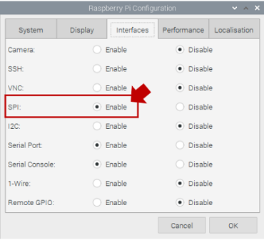
Software Installation and Configuration
For interfacing the MCP3008 with the Raspberry Pi, first configure the Raspberry Pi for SPI communication and install software. To configure the Raspberry Pi for SPI, enable the SPI interface. This was tested with Raspberry Pi OS, but versions Bullseye, Bookworm, and others are all compatible. From a terminal window on your Raspberry Pi, start the configuration utility by running sudo raspi-config and navigate to “Interface Options.” In the menu, select “SPI” and enable it. Finally, reboot the Raspberry Pi.
Now that the various configurations are completed, we need to install the proper Python libraries to communicate with the MCP3008. Using pip, install spidev with the command: sudo pip3 install spidev. If you want to control additional GPIO, you can install wiringpi with this command: sudo apt-get install wiringpi. After the installation is completed above, run lsmod | grep spi to verify the MCP3008 is detected. The spi_bcm2835 module should be listed as loaded. Once the MCP3008 is detected, create a Python script to initialize it:
import spidev

import time

# Initialize SPI

spi = spidev.SpiDev()

spi.open(0, 0)  # Bus 0, Device 0 (CE0)

spi.max_speed_hz = 1350000  # Set SPI clock speed (1.35 MHz, within MCP3008 specs)
This code sets up the SPI connection, ensuring compatibility with the MCP3008’s timing requirements (per the datasheet, max clock 3.6 MHz at 5V, adjusted for 3.3V). Save this as a starting point for reading analog data, and test the setup with a simple sensor connected to CH0.
Reading Analog Values: Code Examples
Reading analog values from the MCP3008 on a Raspberry Pi involves sending SPI commands to retrieve 10-bit data from the selected channel. Below is a Python script to read from a single channel (e.g., CH0, connected to a potentiometer):
import spidev

import time

# Initialize SPI

spi = spidev.SpiDev()

spi.open(0, 0)

spi.max_speed_hz = 1350000

def read_adc(channel):

    if channel < 0 or channel > 7:

        raise ValueError("Channel must be 0-7")

    # SPI command: Start bit (1), single-ended (1), channel (3 bits), MSBF (0)

    adc = spi.xfer2([1, (8 + channel) << 4, 0])

    # Combine 10-bit result from response

    data = ((adc[1] & 3) << 8) + adc[2]

    # Convert to voltage (assuming 3.3V VREF)

    voltage = (data * 3.3) / 1023

    return data, voltage
try:
while True:

        raw, volts = read_adc(0)  # Read from CH0

        print(f"Raw ADC: {raw}, Voltage: {volts:.2f}V")

        time.sleep(0.5)

except KeyboardInterrupt:

    spi.close()
This script reads the raw 10-bit value and converts it to a voltage based on a 3.3V reference, printing results every 0.5 seconds. To read multiple channels, loop through channels 0-7:
for channel in range(8):

    raw, volts = read_adc(channel)

    print(f"Channel {channel}: {raw}, {volts:.2f}V")
Common issues include SPI clock mismatches (e.g., exceeding 1.35 MHz at 3.3V) or incorrect wiring. If readings are erratic, verify connections, ensure VREF is stable, and check the datasheet’s timing requirements (e.g., 40 ns minimum SCK period). For USA hobbyists, forums like Reddit’s r/raspberry_pi or FlyWing-Tech’s tutorials offer troubleshooting tips tailored to MCP3008 Raspberry Pi setups.
Example:
A few noteworthy points may be found in the Python code for the example, which is displayed below:
With a sampling time of 0.02 seconds, the sampling rate is 50 samples per second. That is far less than the 6.25 kSamples/s hardware SPI implementation limit and even the 1.72 kSamples/s software limit.
To guarantee a somewhat accurate sample period, the execution loop idea with a time step clock is employed.
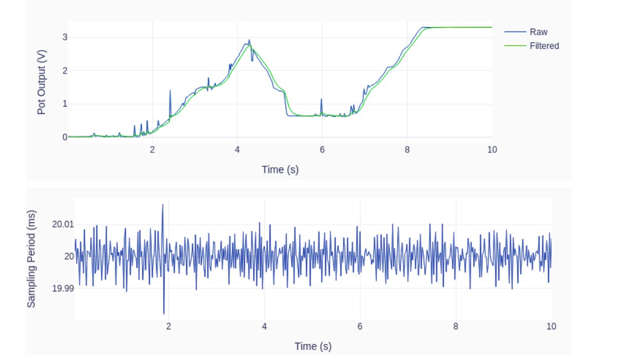
Tasks involving computation and input/output are completed in a time step with lots of leeway. A digital low-pass filter is used in the code to reduce the noise in the analog signal, which is probably caused by the potentiometer’s dubious quality. To further explore its impact, the 2 Hz cutoff frequency can be changed.
A handy Python plotting package, a module called utils.py must be available for import in order for the plotting of the sampled signal to function.
import time
import numpy as np
from utils import plot_line
from gpiozero import PWMOutputDevice, MCP3008

# Creating LED PWM object
led = PWMOutputDevice(16)
# Creating ADC channel object
pot = MCP3008(channel=0, clock_pin=11, mosi_pin=10, miso_pin=9, select_pin=8)
# Assining some parameters
tsample = 0.02  # Sampling period for code execution (s)
tstop = 10  # Total execution time (s)
vref = 3.3  # Reference voltage for MCP3008
# Preallocating output arrays for plotting
t = []  # Time (s)
v = []  # Potentiometer voltage output value (V)
vfilt = []  # Fitlered voltage output value (V)
# First order digital low-pass filter parameters
fc = 2  # Filter cutoff frequency (Hz)
wc = 2*np.pi*fc  # Cutoff frequency (rad/s)
tau = 1/wc  # Filter time constant (s)
c0 = tsample/(tsample+tau)  # Digital filter coefficient
c1 = tau/(tsample+tau)  # Digital filter coefficient
# Initializing filter previous value
valueprev = pot.value
time.sleep(tsample)
# Initializing variables and starting main clock
tprev = 0
tcurr = 0
tstart = time.perf_counter()

# Execution loop
print('Running code for', tstop, 'seconds ...')
while tcurr <= tstop:
    # Getting current time (s)
    tcurr = time.perf_counter() - tstart
    # Doing I/O and computations every `tsample` seconds
    if (np.floor(tcurr/tsample) - np.floor(tprev/tsample)) == 1:
        # Getting potentiometer normalized voltage output
        valuecurr = pot.value
        # Filtering value
        valuefilt = c0*valuecurr + c1*valueprev
        # Calculating current raw and filtered voltage
        vcurr = vref*valuecurr
        vcurrfilt = vref*valuefilt
        # Updating LED PWM output
        led.value = valuefilt
        # Updating output arrays
        t.append(tcurr)
        v.append(vcurr)
        vfilt.append(vcurrfilt)
        # Updating previous filtered value
        valueprev = valuefilt
    # Updating previous time value
    tprev = tcurr

print('Done.')
# Releasing pins
pot.close()
led.close()
# Plotting results
plot_line([t]*2, [v, vfilt], yname='Pot Output (V)', legend=['Raw', 'Filtered'])
plot_line([t[1::]], [1000*np.diff(t)], yname='Sampling Period (ms)')
The outcomes of a single run on my Raspberry Pi 4B are displayed in the graphs below. As I turn the potentiometer knob, watch how the low-pass filter eliminates the noise from the raw data. Naturally, there is a cost to that: the filtered signal now lags behind the original signal. “Zero-lag” filtering techniques can be used after the signal has been acquired in DAQ situations when real-time filtering of the signal is not required. Additionally, take note of the constant 20 ms sampling time step.
Case Studies: Real-World MCP3008 Projects
Home Automation with Temperature Sensors
A home automation project in the USA utilizes the MCP3008 ADC IC to connect multiple LM35 temperature sensors to a Raspberry Pi for indoor climate monitoring. A maker in California developed a smart thermostat using three sensors for different rooms.
The Raspberry Pi processes the data and sends it via MQTT to a Home Assistant server, allowing remote monitoring through a smartphone app. The MCP3008 offers 10-bit resolution and is low-cost, with components priced under $10. This project caters to hobbyists looking to create affordable home automation systems, with resources available on platforms like FlyWIng-Tech.
Robotics with Analog Joystick Control
A robotics hobbyist located in Texas used the MCP3008. To interface an analog joystick with a Raspberry Pi for controlled motor movements in a homemade robotic arm. The analog joystick’s X and Y axes were connected to the MCP3008. It provided control movements with 10-bit resolution and very good responsiveness.
The data from the joystick was in the form of analog voltage, which the Raspberry Pi converted to adjust the PWM signals from the Pi to control servo motors for movement. It would allow the user to fine-tune the various movements of the arm.
The hobbyist posted the project on FlyWIng-Tech, which demonstrated the ease of use of the MCP3008 SPI on the Raspberry Pi. To integrate the analog interface as well as the use of multiple analog inputs. The MCP3008 is an inexpensive option for a hobbyist that costs less than $5.
Environmental Monitoring System
A group of students based in New York created a system for environmental monitoring for a community garden based on the MCP3008 to connect soil moisture and air quality sensors to a Raspberry Pi. The MCP3008 enabled sensors to take readings at the same time, the data was logged to a CSV file (for all the world to see!), and the data was also displayed on a web dashboard using Flask.
This project was cheap and accessible for educational use, costing $2.750 for the MCP3008. The project could be expanded to include more sensors while following the guidelines. It demonstrates the utility of the MCP3008 for various environmental purposes and was advertised around the web forum sharing of documents, for example on the Raspberry Pi Foundation’s blog.
Conclusion
The MCP3008 ADC IC is a popular choice for electronics enthusiasts in the USA, providing an affordable solution for analog-to-digital conversion in Raspberry Pi projects. The MCP3008 is an 8-channel, 10-bit ADC. It works well with SPI (Synchronous Peripheral Interface) and is great for many types of projects in automation, IoT (Internet of things), and simply making things! You will be able to connect and easily read many analog sensors, such as potentiometers, thermisters, air quality monitors, and more using the MCP3008 ADC IC.
In this post, you will find a summary of the features of MCP3008 ADC IC as well as step-by-step guide to interface with and use in your next Raspberry Pi project. We will also include some common FAQs at the bottom of this post. For even more information you can research the MCP3008 at Microchip Forums, Raspberry Pi, and/or online retailers like FlyWing-Tech. You are now ready to begin your next Raspberry Pi project using the MCP3008 and enter into the maker community!
Call to Action
Ready to dive into your next electronics project? Download the official MCP3008 datasheet from Microchip’s website to understand its specifications and applications. Follow a Raspberry Pi tutorial to connect analog sensors, like temperature or light sensors. In the USA, you can buy the MCP3008 ADC IC from retailers like FlyWing-Tech for under $3.
Engage with maker communities on platforms like Reddit, and the Raspberry Pi Foundation forums to share projects and find inspiration. For further development, explore advanced Raspberry Pi sensor projects or IoT integrations. Start building and showcase your work to inspire others!
FAQs About MCP3008 ADC IC
The MCP3008 has a 200 ksps sampling rate and 2.7V-5.5V range; MCP3208 offers 250 ksps and 2.7V-5.0V. MCP3008 is cheaper and ideal for Raspberry Pi projects.
Yes, MCP3008 works with Arduino, ESP32, and STM32 via SPI. Use 3.3V or level shifters for compatibility.
Check wiring, enable SPI in raspi-config, and set clock speed to 1.35 MHz. Ensure stable VREF and grounding.
The MCP3008 supports analog sensors like thermistors, photoresistors, or potentiometers. Connect up to eight sensors to its channels for Raspberry Pi projects.
The MCP3008 offers 10-bit resolution (±1 LSB accuracy) and a 200 ksps sampling rate, ideal for precise analog to digital conversion.
Yes, it supports up to 200 ksps at 5V, sufficient for most Raspberry Pi applications like audio or sensor monitoring.