Introduction
DC motors are electronic devices that are fundamentally used to convert electrical energy into mechanical energy. In robotics and embedded systems, motors are becoming a crucial component for various applications, such as controlling the wheel direction of an electric vehicle, moving the robotic arm in a specified direction, and in pick-and-place automation systems.
DC motors draw high currents, and a microcontroller provides a low-power signal. To control the DC motor, it becomes essential to interface the DC motor with the microcontroller. Therefore, it is difficult to directly interface the motor with the microcontroller because a DC motor operates on high currents, and a microcontroller provides a very low current. This is where the motor drive IC comes into play. Motor driver ICs like L293D amplify the low-power signal from the microcontroller and provide high-current and voltage signals to the DC motor. Therefore, the L293D motor drive IC acts as a bridge between the microcontroller and DC motor to provide precise control over speed and direction.
The L293D is a quadruple high-current motor drive IC design to provide bidirectional drive currents of up to 600 mA at voltages ranging from 4.5V to 36V. This motor drive IC is design to drive inductive loads such as DC motors, solenoids, and relays. The L293D IC features two H-bridge circuits, enabling it to drive two DC motors simultaneously. The H-bridge is a simple electronic circuit that is capable of controlling the direction of a DC motor in either forward or reverse direction.
What is L293D and Why Do We Use it?
L293D is a popular motor drive IC that is widely used in applications that require precise control over motor speed and direction. L293D is a 16 PIN motor drive IC that consists of two independent H-bridge circuits that enable it to control the two DC motors simultaneously.
To interface the microcontroller with a DC motor, you must use a motor drive IC like L293D, because the microcontroller provides a low current, and the DC motor operates in higher currents. The L293D fills this gap by acting as a bridge between the microcontroller and the DC motor. It accepts the low-power signal from the microcontroller and then amplifies it, and provides a high-current and voltage signal to the DC motor.
The L293D also features internal clamping diodes that protect when the motor suddenly stops and generates back EMF. Another prime feature of L293D is its compatibility with both TTL and CMOS logic families. Therefore, it can be easily interface with Arduino, microcontrollers like STM32, and Raspberry Pi. All these features and the L293D capability to act as a bridge between the microcontroller and the DC motor make it useful in various embedded and robotics applications.
L293D PIN Configuration
L293D is a 16-pin motor drive IC that mostly comes in DIP package, and PDIP packages. The PDIP package of L293D has a dimension of 19.80 mm × 6.35 mm. This makes it easy to use in circuit boards and breadboards. The 16 pins of L293D have a unique function and role in controlling the precise control over motor speed and direction. To use L293D in your design application, you must be aware of the role and function of each pin of L293D to efficiently utilize it.
L293D Motor Drive IC PIN Configuration
| PIN Number | PIN Name | Function |
| 1 | 1,2 EN | Enable driver channels 1 and 2 (active high input) |
| 2 | 1A | Controls the direction of Motor 1 (works with IN2). |
| 3 | 1Y | Connects to Motor 1 terminal A. |
| 4 | GND | Common Ground (includes heat sink and GND) |
| 5 | GND | Common Ground (includes heat sink and GND) |
| 6 | 2Y | Connects to Motor 1 terminal B. |
| 7 | 2A | Controls the direction of Motor 1 (works with IN1). |
| 8 | VCC2 | Power VCC for drivers 4.5 V to 36 V |
| 9 | 3,4 EN | Enable driver channels 3 and 4 (active high input) |
| 10 | 3A | Controls the direction of Motor 2 (works with IN4). |
| 11 | 3Y | Connects to Motor 2 terminal A. |
| 12 | GND | Common Ground (includes heat sink and GND) |
| 13 | GND | Common Ground (includes heat sink and GND) |
| 14 | 4Y | Connects to Motor 2 terminal B. |
| 15 | 4A | Controls the direction of Motor 2 (works with IN3). |
| 16 | VCC1 | 5V supply for internal logic translation |

L293D Circuit and Working Operation
The L293D motor driver IC, in its internal circuit, consists of two H-bridge circuits that control the two motors simultaneously and independently. When we interface the L293D motor driver with the microcontroller, it takes the low power input signal from the microcontroller (typically 3V3 volts and 50mA), and provides the high current (typically up to 600mA), and voltages between 5V and 36V. These high currents and voltages drive the DC motors connected at the output pins of the L293D motor driver IC.
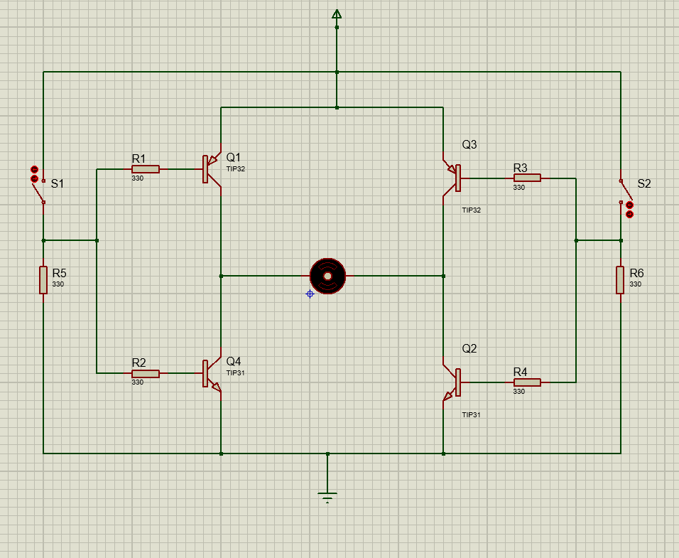
An H-bridge is an electronic circuit use to control the motor direction in forward and reverse. The basic H-bridge circuit consists of four transistors connected in a fashion to control the motor direction in both forward and backward, as shown in the figure below.
Working Operation
An H-bridge circuit consists of four transistor switches. By turning them ON and OFF in a specific manner, we can easily control the direction of the motor. In the circuit shown, the H-bridge consists of four transistor switches Q1, Q2, Q3, and Q4.
When S1=0 & S2=1
When Switch 2 is at high logic, the transistors Q2 and Q1 will conduct and drive the motor in the forward direction. As Switch 1 is open, there is no sufficient base voltage for Q4 to Turn ON, hence Q3 and Q4 will remain in the off condition, and the motor will smoothly run in the forward or clockwise direction as shown in the figure below.

When S1= 1 & S2=0
When Switch 1 is at high logic, the transistors Q3 and Q4 (TIP31) will conduct and drive the motor in the reverse direction. As Switch 2 is open, there is no sufficient base voltage for Q2 to Turn ON, hence Q1 and Q2 will remain in the off condition, and the motor will smoothly run in the reverse or anti-clockwise direction as shown in the figure below.
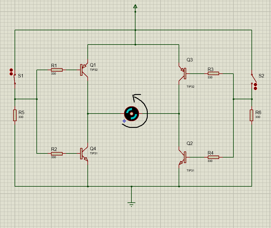
When both switches S1 and S2 are in the ON condition, the motor does not run in either direction and brakes immediately. This condition is the short-circuit condition. When both switches S1 and S2 are in the OFF condition, none of the transistors will Turn ON and the motor will be in a stop condition. The L293D motor driver IC contains two such H-bridge circuits to run the two motors simultaneously in any direction. The working operation of both H-bridge circuits is the same.
Technical Specifications & Parameters
The L293D motor driver IC is famous and widely use in robotic and embedded applications. However, to use the L293D motor drive IC in your design application, understanding and knowledge of its technical specification and parameters are essential for design engineers to efficiently utilize it in design applications and avoid design failures. To get an in-depth analysis of the technical specification and parameters of L293D, refer to its datasheet.
L293D Motor Drive IC Technical Specifications and Parameters
| Parameter | Specification | Function |
| Operating Voltage (Logic supply, VCC1) | 4V to 7V | It is the power to the internal logic circuitry of L293D |
| Motor supply voltage (VCC2) | 4V-36V | Its function is to provide power to motors |
| Output current | Up to 600mA | This is the current per motor |
| Peak output current | Max 1.2A | This is the maximum peak current for short pulses. Exceeding this can damage the IC |
| Input Logic High | Minimum 2.3V | Any voltage value higher than this is recognized as high logic |
| Input Logic Low | Maximum 1.5V | Minimum voltage value to be recognized as low logic |
| Enable pin control | TTL compatible | High = enable motor channel, Low disable motor channel |
| Switching Frequency | Maximum 5KHz | This is use to control the speed of the motor using PWM |
| Thermal shutdown | Available | The L293D internal circuit contains a thermal shutdown feature and protects itself from overheating |
| Internal clamp diodes | Available | Protect the L293D in case back EMF is generated by the motors |
| Operating temperature range | 0°C to +70°C | Suitable for robotic and industrial automation applications |
Circuit Design with L293D
Designing a motor application with L293D requires a comprehensive understanding of its pinout, along with each pin’s function and role. The role and function of each pin is already discussed in the Pin configuration section of this article. In this section, we will discuss how to design an application circuit with the L293D motor driver IC.
Power Supply Connections
The L293D motor driver is a 16-pin IC. VCC1 (pin 16) is a logic power supply, and therefore, connect it with a +5V voltage supply. VCC2 (pin 8) provides voltage to the motors; therefore, connect it according to the motor voltage rating. The pin (4,5,12,13) is the GND pin and thus connect it with the common circuit GND.
Input Control Signals
The pins 1A and 2A (pin 2 & pin 7) are the logic inputs of motor A. The pins 3A and 4A (pin 10 & pin 15) are also the logic inputs, but for motor B. These logic inputs control the direction and speed of motors. The input signal comes from the microcontroller (STM32F103C4) and therefore, connect these pins with the GPIO pins of the microcontroller as shown in the figure below.

For example, when the input 1A is HIGH and the 2A input is LOW, and motor A is connected between the output pins 1Y and 2Y (pin 3 & pin 6), it will start rotating in the forward direction. Similarly, when the input 1A is LOW and the 2A input is HIGH, it will start rotating in the reverse or anticlockwise direction.
Enable Pins Connection
There are two enable pins (1,2 EN & 3,4 EN) for controlling the state of motor A and motor B. When 1,2 EN is high, the motor A responds to the logic input signals. However, when the 1,2 EN pin is low, motor A does not respond to the logic inputs and will be in the OFF condition.
Output Connections
Motor A is connected across the pins 1Y and 2Y (pin 3 & pin 6), and Motor B is connected across the pins 3Y and 4Y (pin 11 and pin 14).
External Components Connections
L293D contains built-in flyback diodes that protect the circuit from the back EMF of motors. Always, connect the 100nF to 47uF capacitor across the supply (VCC2) pin to reduce noise. In a typical application circuit of L293D, the microcontroller provides the input logic and PWM signals to the L293D motor driver. We connect the logic supply (VCC1) with +5V and the motor supply (VCC2) with an 8-36V source, depending on the motor’s operating voltage. We connect the two DC motors across the output terminals of the L293D. By applying the appropriate logic signals and PWM from the microcontroller, we control the speed and direction of the motor.
Common Circuit Applications with L293D Motor Drive IC
Bidirectional Control of DC Motor using L293D and Direction Indicator
The L293D consists of two H-bridge circuits that can precisely control the speed and direction of two DC motors. In this section, we have made a bidirectional motor control circuit that controls the direction of DC motor with direction indicator.
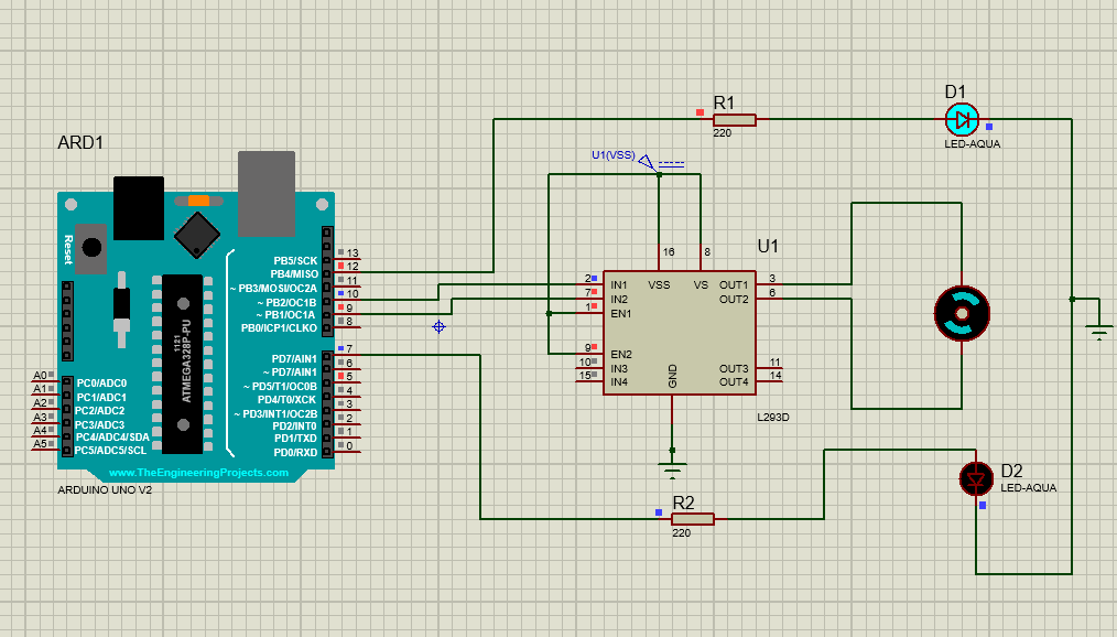
The circuit consists of an Arduino UNO board, two LEDs, DC motor, and one L293D motor drive IC. The microcontroller provides the logic input signals to the L293D motor driver, and at the output of the driver IC, we connect the DC motor. Moreover, connect two LED indicators to show motor is rotating in a clockwise or anticlockwise direction. The Proteus simulation circuit is shown in the figure below.

Both enable pins are connected with positive logic to make both motors respond to the logic input signals. Connect pin 8 and pin 16 with the supply voltage as explain in the circuit design section.
The Arduino IDE is use to write the code for controlling the motor in forward and reverse directions. In the setup() section of code, all the pins are define as outputs, and the motor is running at full speed.
In the loop() section, motor A is set to rotate for 2 seconds and then stops for one second. After that, motor B is set to rotate for 2 seconds and then stop for one second. This process is repeated using the loop function. When the motor starts running, its corresponding LED will also start to blink.
Motor is Rotating in the Forward Direction

Motor is Rotating in the Reverse Direction
Arduino Code
const int IN1 = 9;    // Motor direction pin 1
const int IN2 = 10;   // Motor direction pin 2
const int EN = 5;     // Enable pin (PWM)
const int LED_FWD = 12; // Forward LED
const int LED_REV = 7;  // Reverse LED

void setup() {
  pinMode(IN1, OUTPUT);
  pinMode(IN2, OUTPUT);
  pinMode(EN, OUTPUT);
  pinMode(LED_FWD, OUTPUT);
  pinMode(LED_REV, OUTPUT);
  analogWrite(EN, 255); // Full speed (0-255 range)
}

void loop() {
  // Forward direction
  digitalWrite(IN1, HIGH);
  digitalWrite(IN2, LOW);
  digitalWrite(LED_FWD, HIGH);
  digitalWrite(LED_REV, LOW);
  delay(2000);

  // Stop motor
  digitalWrite(IN1, LOW);
  digitalWrite(IN2, LOW);
  digitalWrite(LED_FWD, LOW);
  delay(1000);

  // Reverse direction
  digitalWrite(IN1, LOW);
  digitalWrite(IN2, HIGH);
  digitalWrite(LED_REV, HIGH);
  delay(2000);

  // Stop motor
  digitalWrite(IN1, LOW);
  digitalWrite(IN2, LOW);
  digitalWrite(LED_REV, LOW);
  delay(1000);
}
Automatic Curtain Opener/Closer using L293D
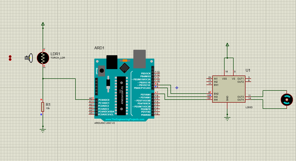
Another interesting home automation application of the L293D motor driver IC is an automatic curtain opener and closer. In the daylight, the curtains are automatically open, and at night, the curtains are automatically closed.
Working Operation
This home automation application requires a DC motor, L293D motor driver IC, Arduino/microcontroller, and an LDR (Light Dependent Resistor). The LDR output acts as a sensor input to the Arduino. The motor will stay OFF in the daylight due to the high resistance of the LDR. The Arduino or microcontroller compares the sensor value with the fixed threshold.
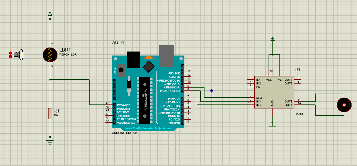
In the daytime, when the light is above the threshold, the Arduino generates the logic inputs such that it will start the motor to run, resulting in the opening of the curtains.
In the nighttime, when the light is below the threshold, the Arduino generates the logic inputs such that it will start the motor to run again, resulting in the closing of the curtains.
Arduino Code
float stepsize = 0.0048;   // Not used here, but kept in case you need later

// L293D connections
// IN1 = pin 7
// IN2 = pin 8
// ENA (Enable pin for Motor 1) = pin 9 (PWM)

void setup() {
  pinMode(9, OUTPUT);   // ENA (Enable for motor)
  pinMode(8, OUTPUT);   // IN2
  pinMode(7, OUTPUT);   // IN1

  // Initialize motor off
  digitalWrite(9, LOW);
  digitalWrite(8, LOW);
  digitalWrite(7, LOW);
}

void loop() {
  int x = analogRead(A0);                 // Read potentiometer value (0–1023)
  int motorSpeed = map(x, 0, 1023, 0, 255); // Map to PWM (0–255)

  // Set motor direction → Forward
  digitalWrite(7, HIGH);   // IN1 = HIGH
  digitalWrite(8, LOW);    // IN2 = LOW

  // Control speed with PWM
  analogWrite(9, motorSpeed);

  delay(10);
}
Practical Application with Simulation: DC Motor Speed & Direction Control with LCD Display
In this section, I will explain the DC motor speed and direction control application with real-time status monitoring of the motor using the LCD (16×2 display), and provide real-time feedback to the user.
Design Statement
Design a low-cost and effective system that can control the speed and direction of the DC motor and provide the real-time status of the DC motor (Motor stopped, forward direction, reverse direction) on the LCD panel.
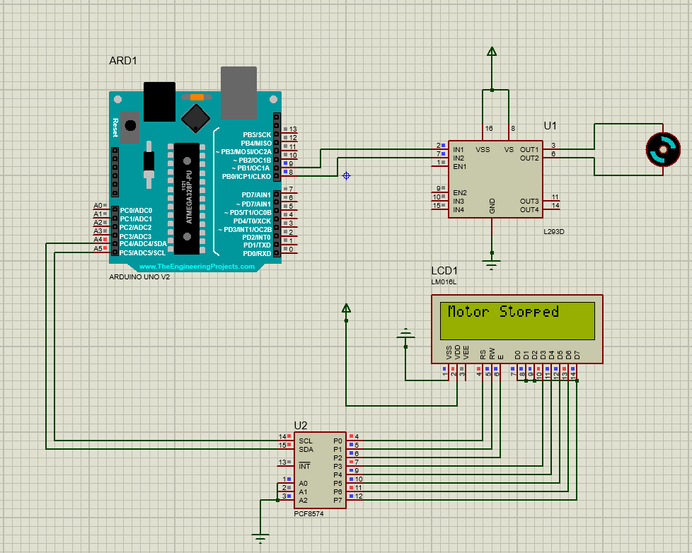
This design can be made using the L293D motor driver IC, Arduino UNO, power supply, LCD (16×2) display, DC motor, and I2C module.
Circuit Diagram and Working Operation
The Arduino UNO in this application acts as the main controller. The code written in the controller generates the logic input signals to the input pins of the L293D motor driver IC. The L293D motor driver rotates the motor in either direction, forward or reverse, using the logic input signals from the microcontroller.
Now, connect the PCF8574 I2C module with the 16×2 LCD (Liquid Colour Display) and interface it with Arduino using the SCL and SDA pins as shown in the circuit diagram. The SDA and SCL are the two pins use in the I2C communication protocol. The SDA is the data line, and the SCL is the clock line.

When the motor is running in the forward direction, the LCD shows the real-time status “Forward Direction” on the LCD. Similarly, when the motor is running in the reverse direction, the LCD shows the real-time status “Reverse Direction” on the LCD. When the motor stops, the LCD shows “Motor Stopped” status on the LCD.


Arduino Code Explanation
The controlling operation and showing the real-time status of the motor is done using the code written in Arduino IDE, and then embedding the .hex file into the Arduino UNO board. The snippet of the code is also shown in the figures below.
The pins 8 and the pin 9 of the motor are configure as the output pins in the code that are going to the L293D as the logic inputs. Three motor functions are define as clockwise, anticlockwise, and motor stopped. Under each function, the logic input of the motor is defined.
In the clockwise function, the logic inputs are define, i.e., pin 8 is HIGH and pin 9 is LOW. In such a situation, the motor will run in the forward/clockwise direction, and the forward direction status will be displayed on the LCD. The anticlockwise and brake functions are also defined in the same way as shown in the code.
Arduino Code
#include <Wire.h>
#include <LiquidCrystal_I2C.h>

// Change 0x20 or 0x3F if LCD does not display
LiquidCrystal_I2C lcd(0x20, 16, 2);

int motorPin1 = 8;
int motorPin2 = 9;

void setup() {
  lcd.init();
  lcd.begin(16, 2);     // Important for Proteus
  lcd.backlight();
  delay(200);           // Allow LCD to settle

  pinMode(motorPin1, OUTPUT);
  pinMode(motorPin2, OUTPUT);

  lcd.print("Motor Control");
  delay(1000);
}

void loop() {
  clockwise();
  delay(5000);

  brake();
  delay(2000);

  anticlockwise();
  delay(5000);

  brake();
  delay(2000);
}

// Custom functions
void clockwise() {
  lcd.clear();
  lcd.setCursor(0,0);
  lcd.print("Forward Direction");
  digitalWrite(motorPin1, HIGH);
  digitalWrite(motorPin2, LOW);
}

void anticlockwise() {
  lcd.clear();
  lcd.setCursor(0,0);
  lcd.print("Reverse Direction");
  digitalWrite(motorPin1, LOW);
  digitalWrite(motorPin2, HIGH);
}

void brake() {
  lcd.clear();
  lcd.setCursor(0,0);
  lcd.print("Motor Stopped");
  digitalWrite(motorPin1, LOW);
  digitalWrite(motorPin2, LOW);
}
Advantages and Limitations of L293D
The L293D motor driver IC is, without a doubt, the most famous and cost-effective IC in controlling the DC motor speed and direction. It is widely use in robotics and embedded applications that such as line follower robots, home automation, and pick and place robotic devices. However, the L293D motor drive IC does have some limitations. In this section, we will explain the advantages and limitations of the L293D motor driver IC.

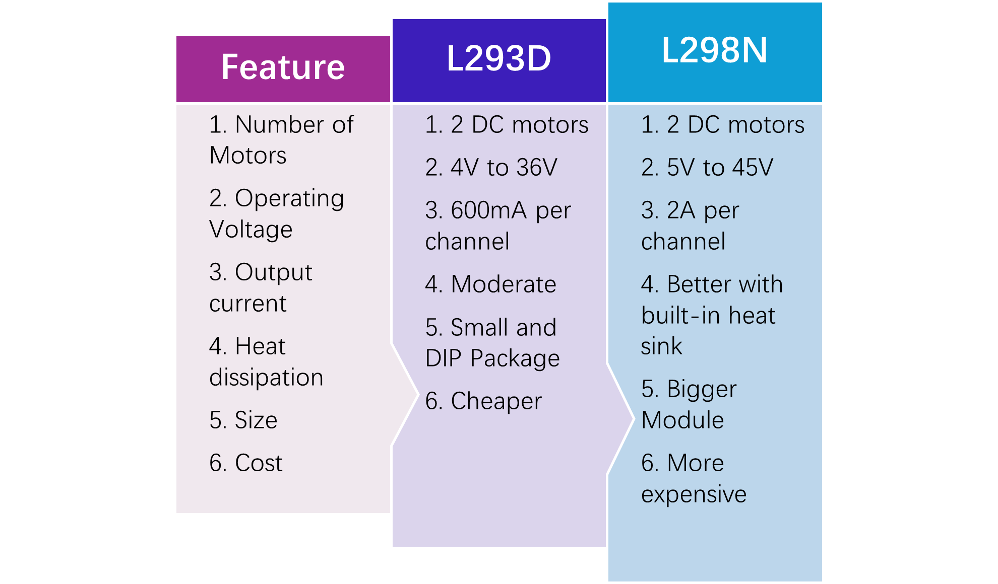
Which is Better: L293D VS L298N
L293D and L298N are both motor drive ICs that are primarily use for controlling the speed and direction of a motor. However, both motor driver ICs have some differences. Using these differences the designer can choose which one is suitable for their design applications.
Conclusion
To sum up, L293D is without a doubt a robust, cost-effective, and efficient motor drive IC that is widely use in robotics and automation applications such as line following robots, and home automation systems. Understanding the L293D pinout, circuit design, working operation, and technical specification is essential for hobbyists, electronic design engineers, and professionals to design efficient applications. This article covered a comprehensive guide on the L293D motor driver IC that includes its pinout, circuit design, working operation, and common design applications with software simulations.
Frequently Asked Questions (FAQ)
Q1. Can I directly connect the motor to the Arduino without the L293D?
No, Arduino only provides 20-50mA current, and the motor requires a higher current to operate. L293D takes the low current and amplifies it to drive the motor. Therefore, L293D must be use to drive the motor with Arduino.
Q1. Can L293D control motor speed?
Yes, L293D is specifically design for controlling the speed and direction of the motor. By using the PWM from the microcontroller, we can control the motor speed using the L293D.
Q2. Which one is better: L293D and L298N?
L293D handles current up to 600mA, and L298N handles current up to 2A. Therefore, the L293D motor driver is use for small motors and low-cost projects. Whereas the L298N high-power motors and industrial projects.
Q3. What is the maximum current the L293D motor driver can handle?
The L293D motor drive can handle a maximum of 600mA current.
Q4. Why use L293D instead of H-Bridge circuits?
The H-bridge requires transistors to construct a circuit. Whereas the L293D is a compact and ready-to-use IC that reduces design time and circuit board space.
Q5. Is L293D suitable for robotic applications?
Yes, L293D is widely use in small to medium robotic applications such as line follower robots, obstacle-avoiding robots, and robotic arms.