Introduction
Modern electronic devices are current sensitive, and accurate measurement of the current of these devices becomes crucial for device safety, control, and energy efficiency. One such module that is perfect for current measurement is the ACS712 current sensor IC. The ACS712 hall effect sensor is known for its ability to efficiently measure both AC and DC without having any direct electrical contact. Therefore, providing the isolation between high-power circuits and low-power circuits.
The ACS712 current sensor IC is manufactured by Allegro Microsystem, and it works on the principle of the Hall Effect. Therefore, also known as the ACS712 hall effect sensor. The Hall effect principle says that when a current-carrying conductor is placed in a perpendicular magnetic field, a voltage is produced. This voltage is known as the Hall voltage. As per this principle, the ACS712 IC senses the magnetic field that is generated by the current flowing through the conductor.
The ACS712 converts the proportion of this signal into an analog voltage output. The IC operates on a single supply of +5V only. Therefore, making it suitable to use with microcontrollers, data acquisition, and energy monitoring systems. The ACS712 current sensor IC comes in various variants, i.e., 5A,20A, and 30A, making it suitable for a wide range of applications.
The ACS712 has gained popularity because it eliminates the need for bulky transformers and precision shunt resistors. Its high sensitivity and built-in isolation features set it apart from other available solutions and therefore, it is widely use in both low current sensing and high current monitoring, such as battery systems and motor drives. This article provides a comprehensive guide to ACS712 circuit design, pinout, and typical circuit applications, accompanied by simulations.
Overview of ACS712 Current Sensor IC
The ACS712 current sensor IC is developed by Allegro Microsystems and is a highly accurate current-sensing device that operates on the principle of the Hall Effect. It is capable of measuring both AC and DC with a high degree of accuracy. It provides the analog output voltage at the output, which is directly proportional to the input current.
ACS712 has a compact size, which includes galvanic isolation, a signal conditioning circuit that makes it a perfect choice for power electronic and embedded systems applications. Overall, the ACS712 IC consists of three main sections known as a low resistance current conductor, a precision hall effect sensor, and a signal conditioning circuit.
The current to be measured will flow from the low resistance conductor. A precision Hall effect sensor is placed near the low resistance conductor so that it can measure the magnetic field generated by the current flow. This magnetic field generates the voltage known as the Hall Effect voltage. In section three, a signal conditioning circuit amplifies the Hall effect voltage and converts it to the analog output voltage that is proportional to the input sense current.
ACS712 Current Sensor IC Pinout & Package Details
The ACS712 comes in various variants based on the ability to measure the maximum current. All the variants of the ACS712 have 8 pins with different package types. Each pin serves a unique function and role for current sensing in the circuit. Therefore, always consult the datasheet before using it in the circuit because there are different variants of ACS712 are available based on the current measurement requirements. Mostly, it comes in a SOIC package. In this section, I will explain the ACS712 pinout with its different variants.
Pin Configuration of the ACS712 Current Sensor IC

ACS712 Current Sensor IC Package Details
Working Principle of ACS712 Hall Effect Sensor
The ACS712 current sensor IC works on the Hall Effect Principle. This is the magnetic field phenomenon which is discovered by Edwin Hall, hence known as the Hall Effect Principle. This principle says “When a current-carrying conductor is placed in a magnetic field, a voltage is induced known as Hall voltage, which is perpendicular to the magnetic field and direction of current flow.” The ACS712 exactly uses this principle to measure electric current without any direct electrical connection with the high and low power sides. This offers electrical isolation and device safety and making it perfect for various electronic applications.
When a current flows from the low resistance conductor, it generates a magnetic field and the Hall effect sensor senses the magnetic field and induces a voltage, known as the Hall voltage. This voltage is directly proportional to the magnetic field strength and therefore to the input current. The hall voltage is very small and in microvolts. Therefore, in ACS712 consists of a built-in amplifier and signal conditioning circuit that amplifies and filters the hall voltage and produces an analog output voltage on pin VOUT (Pin 7). Thus, the relationship of output voltage (Vout) is as follows;
\[
V_{OUT} = \frac{V_{CC}}{2} + (\text{Sensitivity} \times I_{sense})
\]
Where VCC is the operating supply voltage, sensitivity depends on the specific variant of ACS712 (For the 5A variant, sensitivity is 185mV/A), and Isense is the instantaneous current.
A step-by-step working operation of the ACS712 can be understood with the help of a flow diagram as follows;

Technical Specifications & Parameters
The ACS712 current sensor IC is an industry standard and a highly accurate current measurement IC that is able to measure both AC and DC currents. Therefore, it is one of the most popular choice for designers and electrical professionals to use it in a wide applications range including SMPS, inverters, battery management, EV chargers, microcontroller applications, robotics, power electronics, and industrial automation.
However, understanding the technical specification and parameters of ACS712 is essential for design engineers and professionals to accurately use it in their circuit design. There are various variants of ACS712 available in the market; therefore, always consult the datasheet for your specific variant’s technical specification and parameters. In this section, I will discuss and include the technical specification and parameters of the ±5 A ACS712 current sensor IC (ACS712ELCTR-05B).
Technical Specifications of ACS712 Hall Effect Sensor
Design Guide & Calculations
The ACS712 current sense IC is a highly accurate current measurement IC. However, without a proper understanding of the current sense IC circuit design, one can end up with unstable and less precise current measurement, which can lead to circuit failures. Therefore, understanding and calculations of the ACS712 current sense IC help you to design a precise and stable current sensing circuit. In this section, I will provide a design guide with ACS712, including voltage to current conversion, zero current offset, and filtering.
Output Voltage Concept and Calculation
The output voltage of ACS712 is proportional to the measured current. When no current will flow from the conductor, the output voltage is kept at VCC/2, which is 2.5V in a 5V supply operation. However, when current flows from the conductor, the output voltage starts to increase above VCC/2 or 2.5V in the case of 5V supply operation. Similarly, when the current flows in the opposite direction, the output voltage starts decreasing below VCC/2 or 2.5V.
The relationship between the output current and the current being sense is as follows;
\[
V_{OUT} = \frac{V_{CC}}{2} + (\text{Sensitivity} \times I_{sense})
\]
So, for Isense, the equation can be written as;
\[
I_{sense} = \frac{V_{OUT} – \frac{V_{CC}}{2}}{\text{Sensitivity}}
\]
For example, if the output voltage is 3.425V, the sense current will be;
\[
I_{sense} = \frac{3.425 – \frac{5}{2}}{0.185}
\]
\[
I_{sense} = 5A
\]
Design of Measurement Circuit
- Connect the Vout (pin 7) to the microcontroller’s GPIO or ADC pin of the microcontroller. For full-scale utilization, use a 5V reference ADC.
- Always use a 0.1uF capacitor with Vout (pin 7) and GND (pin 5) to reduce the noise.
Power Supply and Layout Considerations
- ACS712 operating supply voltage is 5V. Therefore, use a 5V regulated supply with minimum ripple to ensure accuracy.
- Always use a decoupling capacitor of 0.1uF close to the VCC (pin 8)
Typical Circuit Connection
- VCC (Pin 1): Connect to a stable +5V DC regulated supply.
- GND (Pin 2): Connect to system ground.
- VOUT (Pin 7): Connect to an analog input pin of the microcontroller (e.g., A0 on Arduino).
- IP+ and IP− (Pins 3–6): Connect in series with the load circuit whose current you want to measure.
Common Circuit Applications with ACS712 Current Sensor IC
The ACS712 current sensor IC is primarily use to measure the current of sensitive circuits such as motor drive circuits, battery management systems, EV charger circuits, and Switch Mode Power Supplies. There are various circuits where we need to accurately measure the current drawn by the circuit to ensure circuit safety and protection. In this section, I have explain some typical application circuits of ACS712 and their interfacing with the Arduino UNO board.
DC Motor Current Measurement Circuit Using ACS712-05
The ACS712 current sensor IC is primarily use to measure the current of sensitive circuits. One such application where we need to measure the current for circuit safety and protection is a DC motor drive circuit. In this application, we are measuring the real-time current drawn by the motor using the ACS712 current sensor IC.
The output voltage from the ACS712 at pin 7 is given to the microcontroller, where we convert it into a readable current value and display it on the serial monitor.

In our application circuit, we have use an ACS712 current module for measuring the DC motor current continuously and sending it to the serial monitor. Connect the VCC pin of the sensor with the 5V regulated supply voltage, and connect pin 5 of ACS712 with the common GND. To interface the current sensor ACS712 with the microcontroller, connect the Vout (pin 7) of the sensor with the analog GPIO pin of A0, as shown in the figure. Now, we connect the pin IP+ and IP- of the current sensor module in series with the DC motor and the supply source, as shown in the figure.
When the motor starts to run, it draws the current depending on its speed and load. The ACS712 senses this current and generates the analog output voltage at Vout (pin 7). This analog output voltage is given to the microcontroller input pin A0. The microcontroller converts this analog voltage to a digital value using the ADC and displays it on the serial monitor as shown in the figure. This circuit is use in various applications that include DC motor current control, protection circuits when overcurrent is detected, motor control systems, and battery management systems.
Arduino Code:
const int analogInPin = A0;     // Analog input pin
const float sensitivity = 0.185; // Sensitivity factor for ACS712-05 (185 mV/A)

void setup() {
  Serial.begin(9600);  // Initialize serial communication
}

void loop() {
  int sensorValue = analogRead(analogInPin);
  float current = ((sensorValue - 512) * (5.0 / 1023.0)) / sensitivity;

  Serial.print("Current (ACS712-05): ");
  Serial.print(current);
  Serial.println(" A");

  delay(1000);  // Delay for readability (adjust as needed)
}
DC Current Measurement & LCD Display System using ACS712 Current Sensor IC
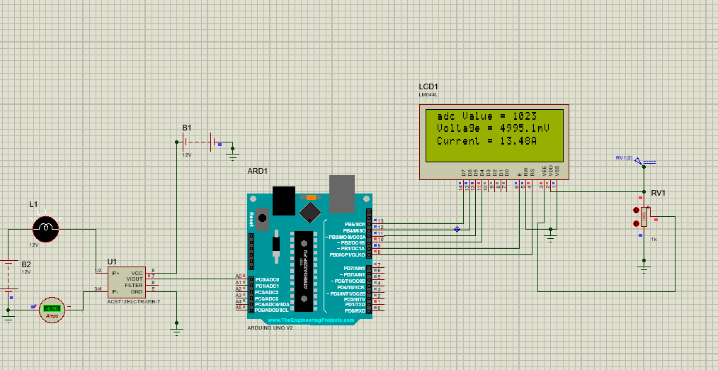
In this application circuit, we have use a current sense IC instead of the ACS712 current sense module. Using the current sense IC, Arduino, we have monitored the real-time current flowing through the DC load and displayed it on the LCD.
The ACS712 measures the current flowing through a DC load and outputs an analog voltage proportional to the current. The Arduino reads this voltage via its analog input (A0), processes it, and displays the real-time current (in amperes) along with the raw ADC value and corresponding voltage on both the LCD and the Serial Monitor. This circuit is useful in many applications that include DC load monitoring, battery performance monitoring, and power supply diagnostics.
When the current flows through the conductor, it produces the magnetic field, and the Hall Effect sensor ACS712 senses the magnetic field and measures the current flowing through the DC circuit. The load is connected with the terminals of IP+ and IP- of the sensor, ensuring that all current must pass through the sensor.
When the sensor detects the current flowing through the conductor, it produces the analog voltage at the Vout pin of the sensor. The reference of the sensor is set to VCC/2. When no current will flow from the conductor the the output will be 2.5V. However, when the current starts flowing from the conductor, this output voltage increases, and when the current flows in the opposite direction, it starts decreasing from 2.5V.
This output voltage is given to the analog GPIO of the Arduino, where it converts it into actual current and displays it on the LCD as shown in the figure below.

Arduino Code
// include the library code:
#include <LiquidCrystal.h> //library for LCD

// initialize the library with the numbers of the interface pins
LiquidCrystal lcd(8, 9, 10, 11, 12, 13);

//Measuring Current Using ACS712

const int analogchannel = 0; //Connect current sensor with A0 of Arduino
int sensitivity = 185; // use 100 for 20A Module and 66 for 30A Module
int adcvalue= 0;
int offsetvoltage = 2500;
double Voltage = 0; //voltage measuring
double ecurrent = 0;// Current measuring

void setup() {
 //baud rate
 Serial.begin(9600);//baud rate at which arduino communicates with Laptop/PC
 // set up the LCD's number of columns and rows:
 lcd.begin(20, 4); //LCD order
 // Print a message to the LCD.
 lcd.setCursor(1,1);//Setting cursor on LCD
 lcd.print("WELCOME TO FLYWING TECH LIMITED");//Prints on the LCD
 lcd.setCursor(4,2);
 lcd.print(".com");
 delay(3000);//time delay for 3 sec
 lcd.clear();//clearing the LCD display
 lcd.display();//Turning on the display again
 lcd.setCursor(1,0);//setting LCD cursor
 lcd.print("Reading Values from");//prints on LCD
 lcd.setCursor(1,1);
 lcd.print("DC Current Sensor");
 lcd.setCursor(5,2);
 lcd.print("ACS 712");
 delay(2000);//delay for 2 sec
}

void loop() //method to run the source code repeatedly
{

 adcvalue = analogRead(analogchannel);//reading the value from the analog pin
 Voltage = (adcvalue / 1024.0) * 5000; // Gets you mV
 ecurrent = ((Voltage - offsetvoltage) / sensitivity);

//Prints on the serial port
 Serial.print("Raw Value = " ); // prints on the serial monitor
 Serial.print(adcvalue); //prints the results on the serial monitor

 lcd.clear();//clears the display of LCD
 delay(1000);//delay of 1 sec
 lcd.display();
 lcd.setCursor(1,0);
 lcd.print("adc Value = ");
 lcd.setCursor(13,0);
 lcd.print(adcvalue);

 Serial.print("\t mV = "); // shows the voltage measured
 Serial.print(Voltage,3); // the '3' after voltage allows you to display 3 digits after decimal point

 lcd.setCursor(1,1);
 lcd.print("Voltage = ");
 lcd.setCursor(11,1);
 lcd.print(Voltage,3);
 lcd.setCursor(17,1);
 lcd.print("mV");//Unit for the voltages to be measured

 Serial.print("\t ecurrent = "); // shows the voltage measured
 Serial.println(ecurrent,3);// the '3' after voltage allows you to display 3 digits after decimal point

 lcd.setCursor(1,2);
 lcd.print("Current = ");
 lcd.setCursor(11,2);
 lcd.print(ecurrent,3);
 lcd.setCursor(16,2);
 lcd.print("A"); //unit for the current to be measured
 delay(2500); //delay of 2.5 sec
}
Advantages and Limitations of the ACS712 Current Sensor IC
Like every IC, the ACS712 current sensor IC comes with its own advantages and limitations. The ACS712 Hall Effect sensor is widely use in industry due to its ability to accurately measure both AC and DC currents without having any external components or precise shunt resistors. However, ACS712 has its own limitations. Therefore, it is important to consult the ACS712 current sense limitations when integrating it into your circuit design. In this section, I will cover the core advantages and major limitations of the ACS712 current sense IC.

ACS712 VS Alternatives
Conclusion
In conclusion, the ACS712 current sensor IC is a highly accurate and precise current measurement IC that is widely use in many electronic applications, including power electronics, microcontrollers, and robotics. The ACS712 works on the principle of the Hall effect and provides electrical isolation between high current and low voltage control circuitry. This ensures device safety and protection. Understanding the ACS712 circuit design, its pinout, design calculations, and technical specification & parameters are essential for design engineers and professionals to accurately integrate the ACS712 into their circuit applications. This article covers all these aspects with typical applications, circuits, and their simulations in Proteus software.
Frequently Asked Questions (FAQ)
Q1. What is the ACS712 current sense used for?
The ACS712 IC is primarily use to measure both AC and DC currents in electronic circuits. It produces the analog output voltage that is directly proportional to the measure current.
Q2. Can the ACS712 current sense IC measure both AC and DC currents?
Yes, ACS712 is a highly accurate and precise current sensor IC that is primarily use to measure both AC and DC currents in electronic circuits.
Q3. What are some of the available variants of ACS712?
The ACS712 current sensor comes in three variants: ±5A (ACS712-05B), ±20A (ACS712-20A), and ±30A (ACS712-30A). Each version has a different sensitivity and measurement range.
Q4. Why does the ACS712 output a voltage of 2.5V when no current is flowing?
The ACS712 supply voltage is 5V, and 2.5V is its zero-offset voltage, i.e., VCC/2. This represents the sensor midpoint bipolar range. Therefore, when no current flow, the sensor outputs 2.5V. However, when current starts flowing, it increases from 2.5V, and when current flows in the opposite direction, it decreases from 2.5V.
Q5. How can I reduce the noise in the ACS712 circuit?
To reduce the noise in the ACS712 circuit, always use a 100nF capacitor between the Filter (pin 6) and GND (pin 5).
Q6. Can the ACS712 Hall Effect sensor measure current in both directions?
Yes, a Hall Effect sensor or a current sense IC (ACS712) can measure current in both directions. When the current increases in one direction, it produces an output voltage above 2.5V, and when the current is flowing in the opposite direction, it produces an output voltage below 2.5V.
Q7. What are some common applications of the ACS712 current sense IC?
This current sense IC is use in many applications, including motor drive, battery management systems, power supply monitoring, inverter systems, robotics, IoT, and home automation systems.
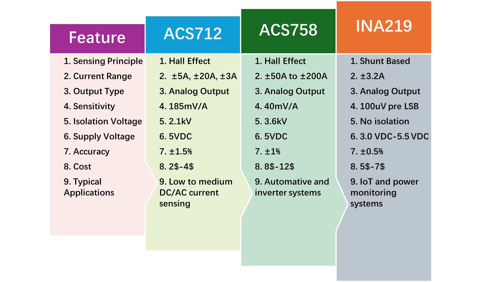
Q8. What are some of the alternatives to the ACS712 current sense IC?
Some of the widely available alternatives to ACS712 are ACS758, ACS770, INA219, and ACS723. Using any of these alternatives will depend solely on the specific application.
