A rocker switch looks simple from the outside. You press one side down, the other side rises, and the circuit turns on or off.
But once you look at the back of the switch, things can get confusing.
Some rocker switches have two pins. Others have three, five, six, or even seven. Some are marked with PWR, ACC, and GND, while others only use numbers. If the switch has an LED, you also need to know whether the light is powered by the load, by a separate backlight circuit, or by the vehicle’s dash light system.
That is where many DIY wiring jobs go wrong.
A rocker switch is one of the most common electrical switches used in vehicles, boats, appliances, control panels, power strips, and industrial equipment. It is popular because it is easy to operate, gives clear ON/OFF feedback, and can be used in many low-voltage and high-voltage applications.
In this guide, we’ll explain what a rocker switch is, how it works, the different types available, how to wire a rocker switch safely, and how to troubleshoot common problems.
We’ll also cover lighted rocker switches, pin configurations, relay wiring, IP ratings, and the key things to check before buying one.
What Is a Rocker Switch?
A rocker switch is an electrical switch that opens or closes a circuit using a rocking motion. When you press one side of the switch, it moves down while the other side moves up, similar to a seesaw.
This is why rocker switches are sometimes called seesaw switches.
The basic job of a rocker switch is simple: it controls whether current can flow through a circuit. In the ON position, the internal contacts connect and allow current to pass. In the OFF position, the contacts separate and stop the current.
You’ll find rocker switches in many everyday applications, including:
- Vehicle dashboards
- Marine switch panels
- Power strips
- Home appliances
- Industrial control panels
- Workshop equipment
- LED light bars
- Fans, pumps, and small motors
A rocker switch is often preferred when the user needs a clear, easy-to-press control with visible ON/OFF status.
If you are selecting a switch for a new design or replacement project, Flywing Tech offers a wide range of rocker switches for panel, automotive, appliance, and industrial applications.
How Does a Rocker Switch Work?
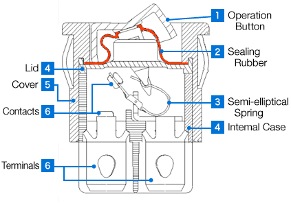
Inside a rocker switch, there is a small mechanical structure that moves when you press the actuator.
The actuator is the visible part you press with your finger. When it rocks to one side, it pushes internal contacts together or pulls them apart. These contacts are conductive metal pieces that either complete or break the circuit.
In a basic ON/OFF rocker switch, the operation is simple:
- Switch OFF: the circuit is open, so current cannot flow.
- Switch ON: the circuit is closed, so current flows to the connected device.
Some rocker switches stay in position after you press them. These are called maintained or latching rocker switches.
Others return to their original position when released. These are called momentary rocker switches.
A maintained rocker switch is used for lights, fans, pumps, and power controls.
Main Parts of a Rocker Switch
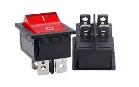
A rocker switch is small, but it has several important parts.

| Component | Purpose |
| Actuator / Rocker | The part you press to turn the circuit ON or OFF |
| Housing | The outer body that holds the internal mechanism |
| Contacts | Metal pieces that open or close the circuit |
| Springs | Help the switch latch or return to position |
| Terminals | Pins or tabs where wires connect |
| LED indicator | Optional light that shows switch status |
| Seal or gasket | Protects against dust, water, or moisture |
In automotive and marine applications, the terminal layout and sealing quality are especially important. A weak terminal, poor ground, or low IP rating can lead to intermittent operation, corrosion, or switch failure.
Rocker Switch vs Toggle Switch vs Push Button Switch
Rocker switches, toggle switches, and push button switches can all control electrical circuits. The difference is mainly in how they are operated and where they work best.
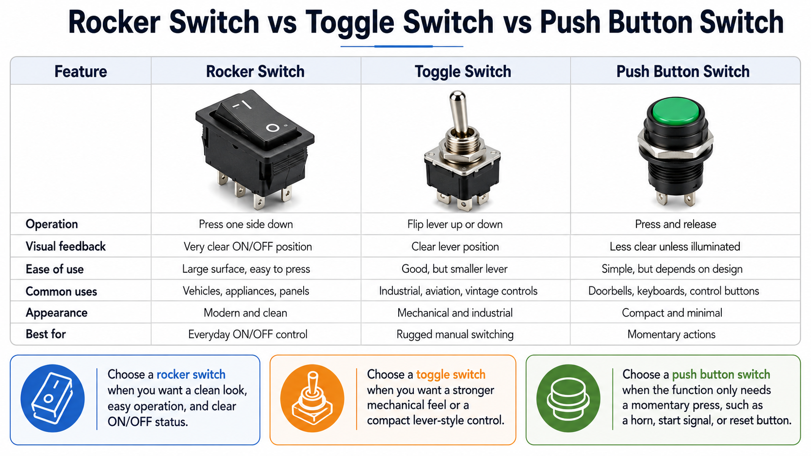
Choose a rocker switch when you want a clean look, easy operation, and clear ON/OFF status.
Then you can choose a toggle switch when you want a stronger mechanical feel or a compact lever-style control.
Choose a push button switch when the function only needs a momentary press, such as a horn, start signal, or reset button.
Types of Rocker Switches by Configuration
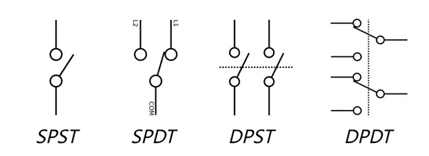
To understand rocker switches properly, you need to know two basic terms: pole and throw.
A pole means the number of separate circuits the switch can control.
A throw means the number of output paths each circuit can connect to.
For example, a simple ON/OFF rocker switch usually controls one circuit and has one output path. That makes it an SPST switch.
SPST Rocker Switch
SPST means Single Pole Single Throw.
This is the most basic rocker switch type. It controls one circuit and has two positions: ON and OFF.
It is commonly used for:
- LED lights
- Fans
- Small pumps
- Power strips
- Appliance power switches
- Basic vehicle accessories
A basic SPST rocker switch usually has 2 or 3 pins.
A 2-pin version simply switches power in and out. A 3-pin version often includes a ground terminal for an indicator light.
For basic ON/OFF control, a panel-mount SPST rocker switch such as the TE Connectivity / AMP 1-1571095-0 is suitable for applications where a durable 20A-rated switch is required.
SPDT Rocker Switch
SPDT means Single Pole Double Throw.
This type controls one circuit but can switch the input between two outputs. It may have ON-ON or ON-OFF-ON positions.
SPDT rocker switches are useful when you want to select between two options, such as:
- Two power sources
- Two lighting modes
- Two devices
- Navigation and anchor light functions
- Motor direction control in simple setups
A typical SPDT rocker switch has 3 pins.
DPST Rocker Switch
DPST means Double Pole Single Throw.
This switch controls two separate circuits at the same time. Both circuits turn ON or OFF together.
DPST rocker switches are common in:
- Appliances
- Industrial equipment
- Dual-circuit control systems
- Some AC power applications
A DPST rocker switch usually has 4 pins.
For applications where one switch needs to control two circuits at the same time, a DPST rocker switch such as TE Connectivity / Alcoswitch PRDDB1-16F-BA000 is a relevant example.
DPDT Rocker Switch
DPDT means Double Pole Double Throw.
This is a more advanced rocker switch. It is like having two SPDT switches inside one body. It can control two circuits and switch each one between two outputs.
DPDT rocker switches are commonly used for:
- DC motor reversing
- Polarity reversal
- Linear actuators
- Marine control panels
- Complex electrical switching
A DPDT rocker switch usually has 6 pins.
For applications that require polarity reversal or dual-circuit switching, a DPDT rocker switch such as TE Connectivity / AMP 1977069-6 is a better fit than a basic ON/OFF switch.
Rocker Switch Pin Configurations Explained
One of the most confusing parts of wiring a rocker switch is the number of pins on the back.
The pin count depends on the switch type, whether it has LED illumination, and whether it controls one or more circuits.
Always check the wiring diagram printed on the switch body or provided by the manufacturer. Pin layouts are not universal.
2-Pin Rocker Switch
A 2-pin rocker switch is the simplest version.
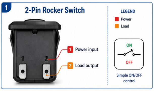
| Pin | Function |
| Pin 1 | Power input |
| Pin 2 | Load output |
This switch simply interrupts the positive wire going to the load.
When the switch is ON, power flows from Pin 1 to Pin 2. When the switch is OFF, the connection is open.
A 2-pin rocker switch is best for simple ON/OFF control where no LED indicator is needed.
3-Pin Rocker Switch
A 3-pin rocker switch is common in automotive and DIY projects.
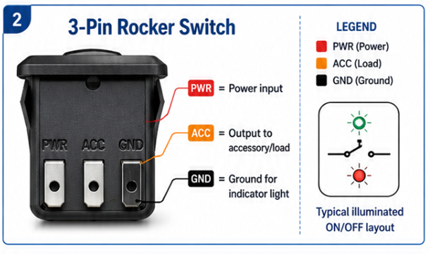
For a basic illuminated ON/OFF switch, the terminals are usually:
| Pin / Marking | Function |
| PWR | Power input |
| ACC | Output to accessory/load |
| GND | Ground for indicator light |
The switch controls power between PWR and ACC. The GND terminal is normally used for the built-in LED.
A 3-pin rocker switch is commonly used for:
- LED light bars
- Small fans
- Auxiliary lights
- Pumps
- 12V accessories
For SPDT rocker switches, the three pins may instead be:
| Pin | Function |
| Common | Input |
| Output 1 | First switched output |
| Output 2 | Second switched output |
This is why you should never assume the wiring based only on pin count.
4-Pin Rocker Switch
A 4-pin rocker switch is usually a DPST switch.

It controls two separate circuits at the same time.
| Pin | Function |
| Pin 1 | Power input for Circuit 1 |
| Pin 2 | Load output for Circuit 1 |
| Pin 3 | Power input for Circuit 2 |
| Pin 4 | Load output for Circuit 2 |
This is useful when one switch needs to control two lines together, such as live and neutral in some AC applications or two separate low-voltage circuits.
5-Pin Rocker Switch
A 5-pin rocker switch is very common in automotive and marine applications, especially when the switch has LED illumination.
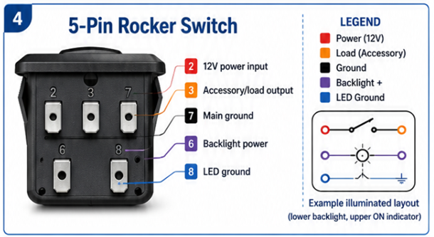
A common 5-pin layout may look like this:
| Pin | Function |
| Pin 2 | 12V power input |
| Pin 3 | Accessory/load output |
| Pin 7 | Main ground |
| Pin 6 | Backlight power |
| Pin 8 | LED ground |
However, pin numbers vary between manufacturers. Some switches use 1, 2, 3, 6, 7. Others use 2, 3, 6, 7, 8.
A 5-pin lighted rocker switch may have two lights:
- A lower backlight to help locate the switch in the dark.
- An upper indicator light that turns on when the accessory is active.
This type is popular for:
- Off-road lights
- Marine navigation lights
- Dash panels
- Vehicle accessories
- Work lights
- Switch banks
6-Pin Rocker Switch
A 6-pin rocker switch is usually a DPDT switch.
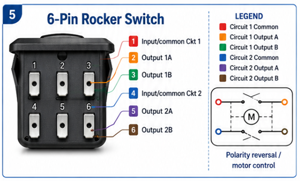
It is commonly used when you need to reverse polarity, such as for a small DC motor.
| Pin | Function |
| Pin 1 | Input/common for Circuit 1 |
| Pin 2 | Output 1A |
| Pin 3 | Output 1B |
| Pin 4 | Input/common for Circuit 2 |
| Pin 5 | Output 2A |
| Pin 6 | Output 2B |
This type is used in motor direction control, linear actuators, and more advanced control panels.
How to Wire a Rocker Switch Safely
Before wiring any rocker switch, treat the circuit as a full system, not just a switch connection. That means checking:
- Voltage rating
- Current draw
- Wire gauge
- Fuse size
- Ground quality
- Load type
- Relay requirement
- Environment
For automotive and marine wiring, the safest approach is to use a fused power source, correct wire size, and secure insulated terminals.
Before you start:
- Disconnect the battery or turn off the power source.
- Confirm the voltage rating of the switch.
- Check the current draw of the device.
- Use the correct wire gauge.
- Add an inline fuse close to the power source.
- Do not exceed the switch’s amp rating.
- Use heat shrink or insulated connectors.
- Test the circuit before final mounting.
A rocker switch should not act as a shortcut around proper circuit protection. If a short occurs and there is no fuse, the wire can overheat quickly.
Wire Gauge and Fuse Selection
Use the device’s current draw to choose the wire and fuse.
| Device Current Draw | Recommended Wire Gauge | Typical Fuse Rating |
| 0–5A | 18 AWG | 5A |
| 5–10A | 16 AWG | 10A |
| 10–15A | 14 AWG | 15A |
| 15–20A | 12 AWG | 20A |
| 20–30A | 10 AWG | 30A |
These are general guidelines. Always check the device specifications, wire length, and installation environment.
For continuous use, it is usually better not to run a switch at its maximum rating. A good rule is to keep the continuous load below around 80% of the switch’s rated capacity.
For 12V automotive circuits, we should select wire size based on current draw, wire length, temperature, and acceptable voltage drop. An automotive wire size chart can help readers understand why longer or higher-current runs often require thicker wire.
How to Wire a Basic 3-Pin Rocker Switch
A 3-pin rocker switch is one of the most common types used in 12V projects.
It usually has:
- Power input
- Accessory/load output
- Ground for LED
Step 1: Identify the Terminals
Look for markings on the switch body.
Usually:
| Marking | Connection |
| PWR | Fused 12V input |
| ACC | Output to accessory |
| GND | Ground |
If there are no markings, use a multimeter in continuity mode.
With the switch OFF, PWR and ACC should be open. With the switch ON, PWR and ACC should show continuity.
Step 2: Connect the Power Wire
Run a wire from the power source to the PWR terminal.
For automotive projects, this should come through an inline fuse placed close to the battery or fuse panel.
Do not connect directly to the battery without a fuse.
Step 3: Connect the Accessory Wire
Connect the ACC terminal to the positive wire of the device you want to control.
For example, if you are wiring an LED light bar, ACC goes to the positive input of the light bar.
Step 4: Connect the Ground Wire
Connect the GND terminal to chassis ground or battery negative.
Use a clean metal grounding point. Paint, rust, or loose bolts can create poor ground and cause the switch LED or accessory to work intermittently.
Step 5: Ground the Device
The device also needs its own ground connection.
The switch ground usually powers the switch LED. It does not always ground the connected device.
Step 6: Test the Circuit
Reconnect power and test the switch.
When the switch is OFF, the accessory should be off.
When the switch is ON, the accessory should turn on, and the indicator light should work if the switch has one.
Use a multimeter to confirm voltage at the input and output terminals.
How to Wire a 5-Pin LED Rocker Switch
A 5-pin LED rocker switch is common in automotive and marine switch panels. It usually has the main switching circuit plus separate LED connections.
A common layout is:
| Pin | Connection |
| Pin 2 | Fused 12V input |
| Pin 3 | Output to accessory |
| Pin 7 | Ground |
| Pin 6 | Backlight power |
| Pin 8 | LED ground |
Again, confirm the actual diagram on your switch.
Method 1: Dash-Controlled Backlight
This method is common in vehicles. The switch backlight turns on with the dashboard lights.
Typical wiring:
| Pin | Connection |
| Pin 2 | Fused 12V input |
| Pin 3 | Accessory positive |
| Pin 7 | Ground |
| Pin 8 | Jumper to ground |
| Pin 6 | Dash light circuit |
This keeps the lower backlight in sync with the vehicle’s lighting system.
Method 2: Constant Backlight
This method keeps the switch visible all the time.
Typical wiring:
| Pin | Connection |
| Pin 2 | Fused 12V input |
| Pin 3 | Accessory positive |
| Pin 7 | Ground |
| Pin 8 | Jumper to ground |
| Pin 6 | Jumper to 12V input |
This is useful for boats, tool panels, or equipment where the operator needs to locate the switch in the dark.
Wiring a Rocker Switch with a Relay
A relay is recommended when the device draws more current than the rocker switch should handle directly.
For example, large LED light bars, compressors, winches, and high-power fans should not be wired directly through a small rocker switch.
A relay lets the rocker switch control a low-current coil, while the relay handles the high-current load.
Standard Automotive Relay Pins
| Relay Pin | Function |
| 30 | Battery power input |
| 87 | Output to device |
| 86 | Relay coil positive |
| 85 | Relay coil ground |
Basic Rocker Switch + Relay Wiring
The rocker switch side:
| Rocker Terminal | Connection |
| PWR | Fused 12V input |
| ACC | Relay pin 86 |
| GND | Ground |
The relay side:
| Relay Pin | Connection |
| 30 | Fused battery positive |
| 87 | Positive input of device |
| 86 | From rocker switch ACC |
| 85 | Ground |
When you turn the rocker switch ON, it sends power to relay pin 86. The relay coil activates, closing the internal contact between pin 30 and pin 87. Power then flows directly from the battery to the device through the relay.
This setup protects the rocker switch and reduces voltage drop in high-current circuits.
Rocker Switch Installation and Panel Mounting
Wiring is only part of the job. The switch also needs to be mounted properly.
Most rocker switches are installed in a panel cutout. The size depends on the switch body.
Common cutout sizes include:
| Switch Type | Approximate Cutout |
| Mini rocker switch | 12mm x 6mm |
| Standard rocker switch | 20mm x 13mm |
| Large rocker switch | 30mm x 22mm |
Always check the switch datasheet or product page before cutting.
Installation Tips
Mark the panel carefully before drilling or cutting.
Use a step drill, hole saw, or panel cutter depending on the switch shape. Remove sharp edges with a file or deburring tool.
The switch should fit snugly, but you should not force it. If the hole is too small, the switch body or retaining clips can crack.
For outdoor, marine, or under-hood use, choose a weatherproof switch and seal the panel opening properly.
IP Ratings for Rocker Switches
If the switch will be exposed to water, dust, mud, or moisture, check the IP rating.
IP stands for Ingress Protection.
The first digit shows dust protection. The second digit shows water protection.
| IP Rating | Protection Level | Best Use |
| IP40 | Basic indoor protection | Indoor panels |
| IP54 | Dust and splash protection | Light outdoor use |
| IP65 | Dust-tight and water-jet resistant | Outdoor equipment |
| IP67 | Dust-tight and temporary immersion protection | Automotive, marine above-deck |
| IP68 | Dust-tight and continuous immersion protection | Harsh marine or wet environments |
For indoor applications, IP40 or IP54 may be enough.
For automotive under-hood, off-road, or marine use, IP67 or IP68 is usually the safer choice.
Common Rocker Switch Applications
Rocker switches are used across many industries because they are simple, durable, and easy to understand.
They are especially useful in panels where the operator needs clear ON/OFF feedback. Depending on the switch design, they can also support illumination, waterproofing, and high-cycle use.
Automotive Applications
In vehicles, rocker switches are commonly used for LED light bars, fog lights, work lights, auxiliary fans, air compressors, winch controls, inverters, interior lighting, and custom dash panels.
They are popular because they are easy to operate, even with gloves, and they can be illuminated for night use.
For high-current accessories, use a relay instead of running full load current through the switch. This protects the switch contacts and improves long-term reliability.
Marine Applications
Marine rocker switches are used for navigation lights, anchor lights, bilge pumps, livewell pumps, deck lights, cabin lights, fishfinder power, and washdown pumps.
Use tinned copper wire, waterproof connectors, and IP67 or IP68 switches where needed.
In exposed areas, avoid using indoor-rated switches. Moisture and salt can quickly corrode terminals and cause intermittent failures.
Industrial Applications
In industrial settings, rocker switches are used in control panels, machinery, pumps, HVAC equipment, conveyor systems, power control units, and lighting systems.
Here, voltage rating, current rating, certification, and durability matter more than appearance.
Industrial rocker switches may need higher mechanical life, stronger housing materials, and approved ratings for the equipment they control.
Home and DIY Applications
For home and workshop projects, rocker switches are often used in power strips, tool panels, aquarium systems, garden lighting, small appliances, DIY electronics, and workbench power controls.
For AC mains wiring, follow local electrical codes and use rated components. If you are not qualified, hire a licensed electrician.
How to Test a Rocker Switch with a Multimeter
A multimeter is the best tool for confirming whether the rocker switch is working.
Continuity Test
Disconnect the switch from power before testing.
Set the multimeter to continuity mode.
Touch one probe to the power input terminal and the other to the output terminal.
When the switch is OFF, the meter should show open circuit.
When the switch is ON, the meter should beep or show very low resistance.
If the reading changes randomly while you move the switch, the internal contacts may be worn.
Voltage Test
For a 12V system, set the multimeter to DC voltage.
With the circuit powered:
- PWR to ground should show battery voltage.
- ACC to ground should show 0V when OFF.
- ACC to ground should show battery voltage when ON.
If PWR has voltage but ACC does not when ON, the switch is likely faulty.
If ACC has voltage but the device does not work, check the device ground or the device itself.
When to Replace vs Repair a Rocker Switch
Most rocker switches are inexpensive, so replacement is often better than repair.
Replace the switch if:
- The housing is cracked.
- The actuator is loose or stuck.
- The switch gets hot.
- The internal contacts are burned.
- The LED has failed and is not replaceable.
- The switch works intermittently even after cleaning.
- There are signs of melting or discoloration.
You may be able to fix the problem if it is only:
- A loose connector
- A corroded terminal
- A weak ground
- A mounting issue
- A dirty external contact
But if the fault is inside the switch body, replacing it is usually safer and faster.
How to Choose the Right Rocker Switch
Choosing the right rocker switch depends on the circuit, environment, and load.
1. Check the Voltage Rating
Use a switch rated for your system voltage.
Common ratings include:
- 12V DC for cars, motorcycles, boats, and small DC projects
- 24V DC for trucks, buses, and some marine systems
- 125V or 250V AC for household or industrial applications
Do not assume an AC-rated switch is suitable for DC unless it is rated for both.
2. Check the Current Rating
The current rating tells you how much load the switch can handle.
Common ratings include:
| Switch Rating | Suitable Use |
| 10A | Small LEDs, light accessories |
| 15A | Medium-duty accessories |
| 20A | Larger lights, pumps, fans |
| 30A | Heavy-duty circuits, often larger switch body |
For continuous use, avoid running the switch right at its maximum limit.
If the device draws high current, use a relay.
3. Choose the Right Pin Configuration
Choose based on what the switch needs to do.
| Need | Recommended Switch |
| Simple ON/OFF | 2-pin or 3-pin SPST |
| ON/OFF with LED | 3-pin or 5-pin |
| Switch between two outputs | SPDT |
| Control two circuits together | DPST |
| Reverse motor direction | DPDT |
| Separate backlight and indicator | 5-pin or 7-pin |
4. Check the Terminal Type
Common terminal types include:
- Spade terminals
- Screw terminals
- Solder terminals
- PCB pins
For automotive and marine use, spade terminals are common because they are easy to crimp and service.
For industrial panels, screw terminals may be preferred.
5. Consider the Environment
For indoor use, a standard rocker switch may be fine.
For vehicles, boats, outdoor equipment, and dusty environments, choose a sealed switch with the right IP rating.
Also consider:
- UV resistance
- Heat exposure
- Vibration
- Saltwater corrosion
- Dust and mud
- Panel thickness
Common Mistakes When Installing Rocker Switches
Many rocker switch problems come from installation mistakes, not bad components.
Not Using a Fuse
A fuse is not optional.
Install an inline fuse close to the power source. If a short happens, the fuse blows before the wire overheats.
Using the Wrong Wire Gauge
Thin wire can overheat, especially with long runs or high-current accessories.
Match the wire gauge to the device current and wire length.
Mixing Up PWR and ACC
PWR is usually the input from the power source. ACC is usually the output to the device.
If you reverse them, the switch may not work correctly, and the LED circuit may behave strangely.
Poor Ground Connection
A bad ground can cause dim LEDs, intermittent operation, or complete failure.
Use clean bare metal, a proper connector, and a secure fastener.
Skipping the Relay for High-Current Loads
Large LED bars, compressors, winches, and high-power fans should usually be controlled through a relay.
The rocker switch should trigger the relay, not carry the full load current.
Using Indoor Switches Outdoors
Moisture can enter the switch, corrode terminals, and cause failure.
Use IP-rated rocker switches for outdoor, under-hood, off-road, and marine applications.
Final Thoughts
A rocker switch is simple to use, but proper wiring matters.
The most important things are choosing the right switch type, identifying the terminals correctly, using the correct wire gauge, and protecting the circuit with the right fuse.
If the device draws higher current, do not force the rocker switch to handle the full load. Use a relay and let the switch control the relay coil.
A good rocker switch installation should be safe, clean, and easy to troubleshoot. Take time to check the pin diagram, test the circuit with a multimeter, and make sure every connection is protected from vibration, moisture, and heat.
That is what separates a reliable installation from one that fails after a few weeks.
For engineers, repair technicians, and DIY builders sourcing reliable switch components, Flywing Tech offers a wide range of rocker switches for automotive, marine, industrial, appliance, and panel-mount applications.
Explore Flywing Tech’s rocker switch selection to compare different configurations, current ratings, terminal styles, and illuminated options for your next electrical project.
Rocker Switch FAQs
What is a rocker switch?
A rocker switch is an electrical switch that rocks back and forth to open or close a circuit. Pressing one side turns the circuit ON or OFF, depending on the switch design.
How do you wire a rocker switch?
For a basic 3-pin rocker switch, connect the PWR terminal to fused power, the ACC terminal to the device, and the GND terminal to ground. The device itself also needs a proper ground connection.
What is the difference between a rocker switch and a toggle switch?
A rocker switch uses a flat actuator that rocks back and forth. A toggle switch uses a lever that flips up or down. Rocker switches usually look cleaner and are easier to press, while toggle switches give stronger mechanical feedback.
How many pins does a rocker switch have?
A rocker switch can have 2, 3, 4, 5, 6, or 7 pins depending on the circuit type and LED configuration. The most common automotive versions are 3-pin and 5-pin rocker switches.
Can I use a rocker switch without a relay?
Yes, if the device current is within the switch rating. For high-current devices, use a relay so the rocker switch only controls the relay coil instead of carrying the full load.
Why does my rocker switch have three pins?
A 3-pin rocker switch usually has power input, accessory output, and ground. The ground is often used for the built-in LED indicator.
Why does my rocker switch LED not turn on?
The most common causes are missing LED ground, wrong polarity, no backlight power, or a failed LED. On many 5-pin switches, the LED ground must be connected separately.
What does IP67 mean on a rocker switch?
IP67 means the switch is dust-tight and protected against temporary water immersion. It is suitable for many outdoor, automotive, and marine above-deck applications.
What amp rocker switch do I need?
Choose a switch rated above your device’s current draw. For continuous use, avoid exceeding around 80% of the switch rating. If the device draws high current, use a relay.
COMMENTS