Introduction
Selecting the right power transistors between MOSFET vs. IGBT plays a crucial role in optimal electronic circuit performance. Against old-style BJT’s, MOSFET (Metal-Oxide Semiconductor Field-Effect Transistors) and IGBT (Insulated Gate Bipolar Transistors) are popular available options. Hobbyists often struggle with the choice between MOSFET and IGBT since both are fully controlled, voltage-driven switches.
MOSFETs and IGBTs have specific characteristics. These traits make each device suitable for different project types. This guide compares both components. It highlights their working principles, performance differences, and key hobbyist applications.
Basics of Power Switching Application Devices
At their core, both MOSFET and IGBT act as fast-switching applications devices used in electronics hobby projects. Their switching capability is utilized in different ways to achieve various results at the output. THe hobbyists therefore ask this questions: which is better MOSFET or IGBT for hobby projects? This guide is all about this question.
What Is a MOSFET?
A MOSFET is a unipolar transistor consisting of 3 terminals: A gate, source, and a drain, as shown in the representative drawing below:
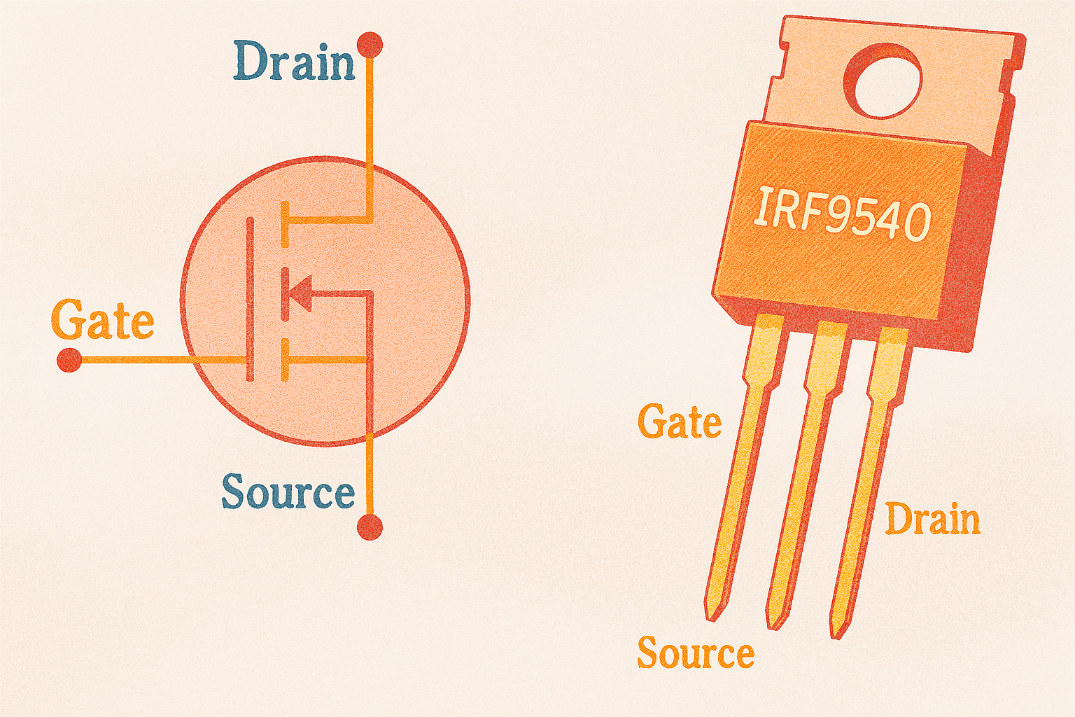
MOSFET uses a voltage-operated insulated gate to conduct the current between its source and drain. At a specific voltage ($V_{GS}$), the MOSFET allows current flow between the Drain and Source terminals. MOSFETs are particularly useful for high-efficiency, high-speed switching (no stored charge delays) because they conduct using majority carriers (electrons or holes only). This is why they are often used in battery-operated electronic loads, circuits, and devices.
They also possess low resistance, offering minimal power wastage due to heat dissipation offering better portability in battery-operated devices.
MOSFETs offer several key benefits. They have low voltage drops at low currents during ON-state. Gate driving for MOSFETs is easy and simple. MOSFET can operate at very high switching frequencies.
What Is an IGBT?
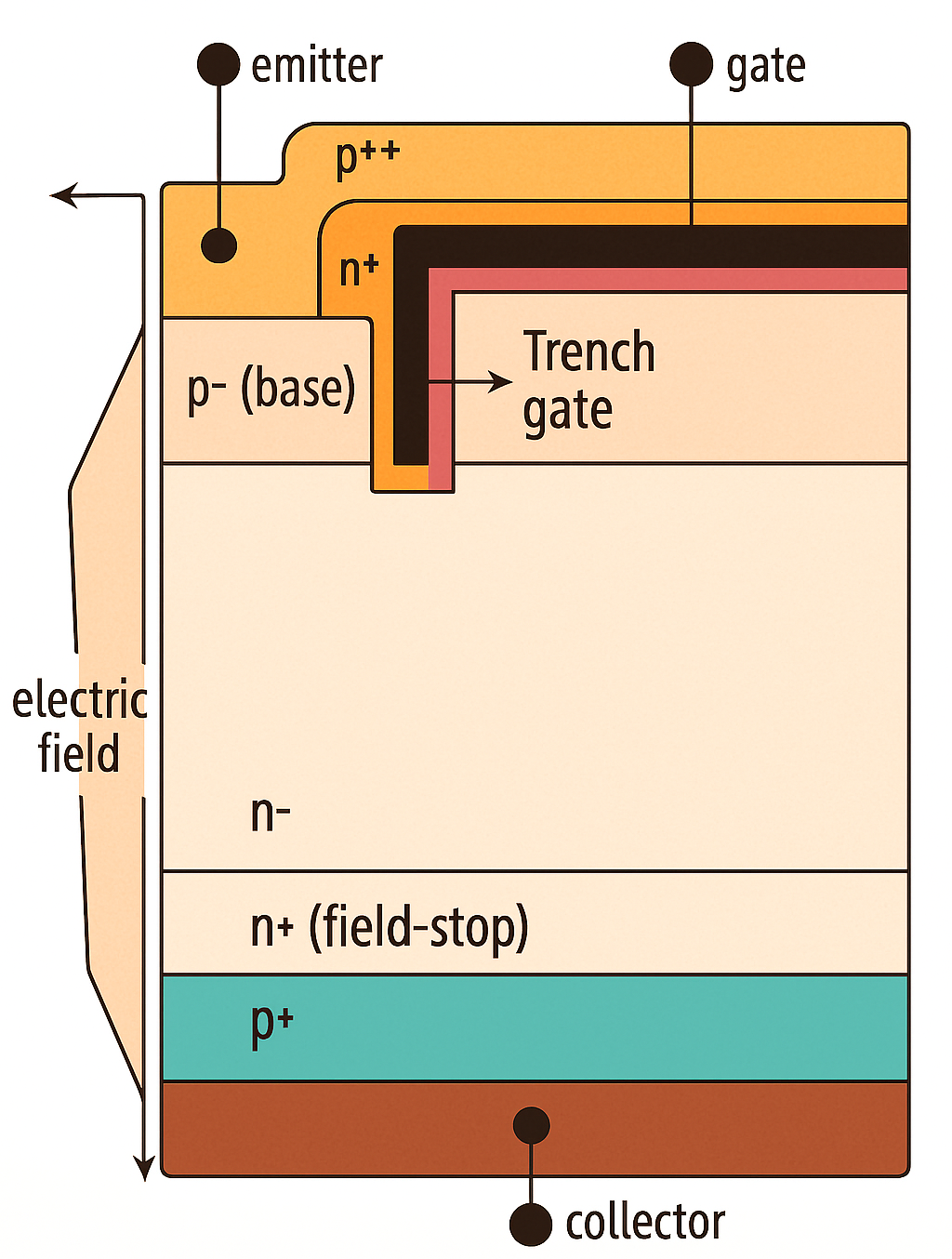
IGBT is a bipolar (conduction using both holes and electrons) electronic switching frequency device like MOSFET in operation. However, it has some advanced capabilities for high-power circuits. These capabilities arise from the fact that IGBT is a hybrid of BJT and MOSFET. At input, it has MOSFET-like voltage drive gate control, and at the output, it has a bipolar output structure that allows conduction using majority and minority carriers. Like MOSFET, an IGBT also consists of three terminals, however, named differently: A gate, collector, and emitter as depicted in the annotated drawing below:

Since an IGBT combines MOSFET’s voltage-driven input structure with BJT’s (Bipolar Junction Transistor), it boasts high-current output handling with balanced switching speed. These multidimensional IGBT capabilities are often suitable for medium-high voltage operating circuits.
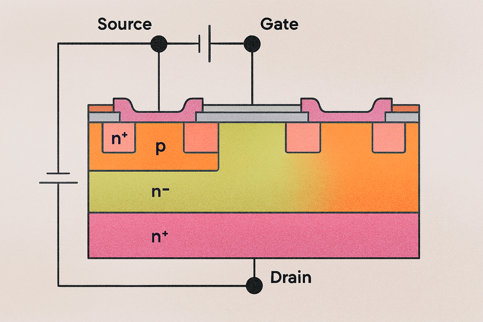
Unlike MOSFETs, typical IGBTs lack an intrinsic body diode, so you must add an external diode (for one-way current flow) to block reverse current in applications like H-bridges or half-bridges before using IGBTs in an electronic circuit. Below is a cross-section diagram of the internal structure of the IGBT:
IGBT offers high current density and low conductivity loss at high voltage levels. That is why a moderate-sized IGBT die can handle a large amount of current (in the range of 45A), with typical IGBTS able to perform well in 300V-600V ranges.
However, since IGBTs also conduct through minority carriers (holes), they leave behind stored charge (tail current), which makes them slow to turn off, effectively translating into relatively a slower switching frequency device.
Key Differences: MOSFET vs. IGBT Characteristics
Both MOSFET and IGBT are electronic switching devices. Which means practically, they have same faunction. Therefore, their performance metrics decide and differentiate their intended application and use cases. Below, we take an extensive and deep look into the key differences of MOSFETS compared to IGBT, considering their characteristics.
Conduction Behavior
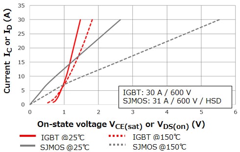
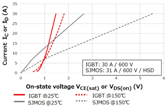
When in the On-state, a MOSFET behaves like a low-value resistor ($V_{DS(on)}=IR_{DS(on)}$). This behavior causes a substantially low voltage drop at low current (see formula above) and is consistently linear as the current increases.
On the other hand, IGBT behaves like a diode $V_{CE(sat)}$ combined with small resistive components. IGBTs excel at maintaining performance even at higher voltage and temperatures (150 °C). IGBT can also maintain a lower drop at these higher current and temperature conditions compared to MSOFET. The following diagram depicts this characteristic of MOSFET and IGBTs:
Switching Speed of MOSFET vs. IGBT
MSOFETs are unipolar devices that do not have any stored charge. Therefore, they are faster than IGBTs at switching. For MOSFETs, switching speed is only limited by charging or discharging at gate capacitances and the device’s intrinsic capacitance. Typical MOSFETS have switching speeds in the hundreds of kHz or even in the MHz range.
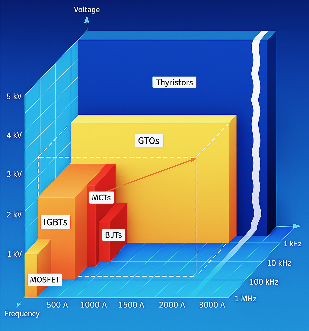
On the contrary, IGBTs have a slower switching speed compared to MOSFETs, due to the carrier accumulation effect, also called the “tail” current. Designers often confine this switching speed to the kHz range to avoid switching loss. Because of this slower switching speed, you will often find IGBTs better suited for projects that require very high voltage and current handling, where switching speeds below 20kHz perform well. The image above shows the switching speeds, current handling, and voltage handling of various power transistors.
Gate Drive Requirements
Both IGBT and MOSFET are voltage-driven devices, with MOSFET often requiring around 10-12V to get in the ON state, and 0V to shut off. IGBTs require comparatively higher voltage, up to 15 volts to get in the On-state; however, unlike MOSFETs, IGBTs may require negative gate bias (-5V or so) to turn off. Below are the MOSFET’s switching characteristics:
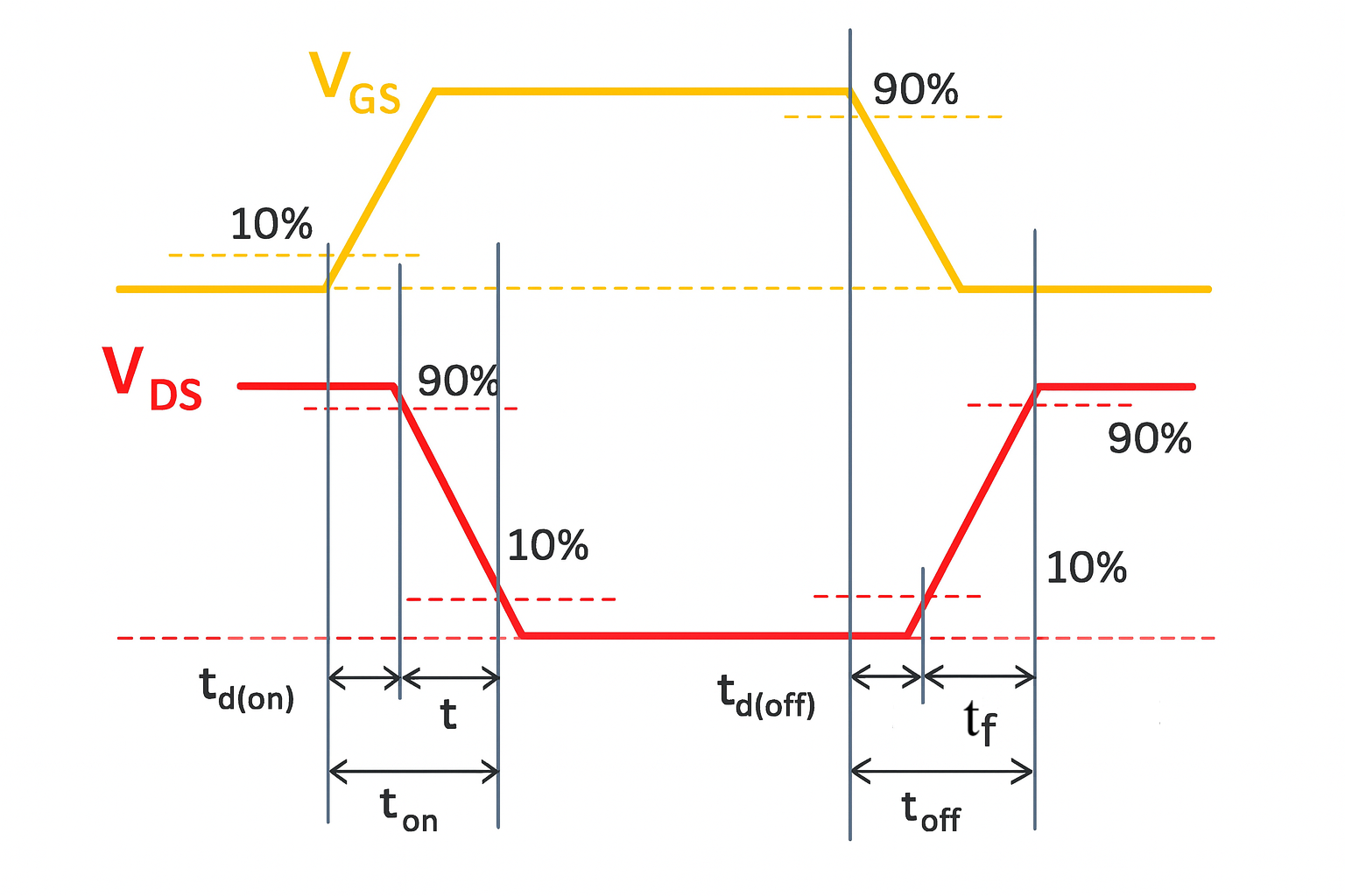
| Symbol | Definition | Detail |
| ${t}_{off}$ | Turn-on delay time | Time from when the gate-source voltage rises above 10% of ${V}_{GS}$ until the drain-source voltage reaches 90% of ${V}_{DS}$ |
| ${t}_{r}$ | Rise time | The time taken for the drain-source voltage to fall from 90% to 10% of ${V}_{DS}$ |
| ${t}_{on}$ | Turn-on time | The turn-on time is equal to ${t}_{don}$+ ${t}_{r}$. |
| ${t}_{{d}({off})}$ | Turn-off delay time | The time from when the gate-source voltage drops below 90% of ${V}_{GS}$ until the drain-source voltage reaches 10% of ${V}_{DS}$ |
| ${t}_{f}$ | Fall time | The time taken for the drain-source voltage to rise from 10% to 90% of ${V}_{DS}$ |
| ${t}_{off}$ | Turn-off time | The turn-off time is equal to ${t}_{doff}+ {t}_{f}$. |
MOSFETs and IGBTs have similar gate drive needs. Use a proper gate driver IC. This ensures reliable circuit operation. The IC should quickly charge and discharge the gate.
These switching speeds and gate charge characteristics also become crucial in deciding the right electronic switching device for the circuit application at hand. Texas Instruments provides these detailed characteristics in their TI Gate Driver Application Note.
Voltage & Current Ratings of MOSFET vs. IGBT
MOSFETS handle low voltage and high-speed switching effectively. Electronic circuits and loads that require low voltage (around 100V) and fast switching are a good fit to use MSOFET. A great example of a low-voltage, high switching MOSFET is a surface mount IRLTS2242TRPBF logic level MSOFET IC, which operates at 12V, and can handle around 7A of current.
On the other hand, IGBTs like RJP60D0DPP-M0#T2 are rated at 600V and can handle up to 45A current. For these specific IC examples of MOSFET and IGBT, an IGBT can handle more than 60 times the MSOFET’s voltage, and 6 times more current conductivity for the same. These IGBTs are often used in inverters as well as induction heating devices, where higher voltages are common occurrences.
Thermal Performance
Many people often overlook thermal performance when selecting between IGBTs and MOSFETs. In some cases, you will find that the thermal characteristics of both devices matter more than you initially expect for a particular application.
The power dissipation in MOSFET is higher than in IGBT for the same load and application. However, note that the IGBT at higher voltage dissipates less power as heat compared to the MOSFET at the same high current-voltage application.
In the above-described cases, particularly and in general as well, both MOSFETs and IGBTs require careful thermal management, taking the application into account for overall optimized performance.
MOSFET vs. IGBT: Safe Operating Area (SOA)
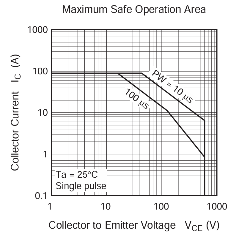
The Safe Operating Area (SOA) is the range of conditions under the curve of a graph where a electronic device can operate safely, without burning out, destroyed, or losing optimal performance. Simply put, the SOA pinpoints the maximum limits of an electronic component under which it can safely operate.
Typically, for MOSFETs and IGBTs, these conditions include voltage and current limits. However, devices are prone to thermal deterioration also includes the thermal characteristics SOA of the device.
An example Collector Current (${I}_{c}$) vs Collector-Emitter Voltage (${V}_{CE}$) SOA of an IGBT (RJP60D0DPP-M0#T2) is given below:
For a MOSFET of similar voltage and current handling capability (FCA36N60NF), an SOA graph of Drain Current (${I}_{D}$) vs Drain-Source Voltage (${V}_{DS}$) is given below:
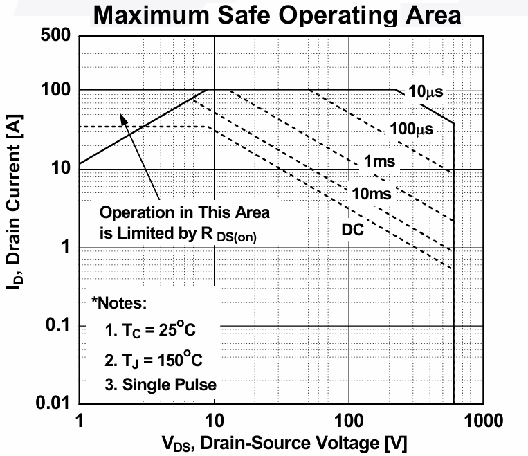
In the above SOA graphs, it is obvious that both IGBT and MOSFET have higher tolerance for short pulses (such as operation in practical PWM applications). However, MOSFET is sharply affected by thermal breakdown compared to IGBT.
Likewise, at higher voltage (up to 1000V), MOSFET has higher limitations, especially for DC current. whereas the IGBT still has better current handling compared to the MOSFET.
When to Use MOSFET vs. IGBT
While MOSFET vs. IGBT comparison includes wide range of factors, both are primary electronic power transistors. is needed in the electronic circuit. So, the decision between the two falls into three key factors:
- Operating voltage
- Operating Current
- Switching Frequency
Answering these questions accurately will allow you to select the right electronic switching device. Let’s look at the typical answers and what the corresponding selection is.
Low Voltage Requirements – Up to 50V
For low-voltage applications typically under 50V, use MOSFETs. This is because at these voltage levels, the ${R}_{DS(on)}$ is substantially low (within milliohms), therefore, offering low conduction loss.
For example, a typical MOSFET (IRFZ44N) rated 55V, 49A will drop approximately. 0.175V while an equivalently rated IGBT will drop upward of 1.5V, both drawing 10A. Additionally, MOSFETs offer higher switching frequency in the range of MHz, suitable for fast DC-DC conversion or in motor control circuit such as DC Motor Speed Controller Circuit.
Medium Voltage Requirements – 50 to 300V
Medium Voltage levels are an open area of contest between MOSFETs and IGBTs. The right selection then depends upon the current and frequency requirements. If high switching speed is still a priority, a super junction MOSFET is an option with a 600V-900V range. In this range, an example is a 200V, 20A switching power supply designer that might still select a MOSFET to operate the power supply at 100kHz for small magnet operation.
IGBTs, on the other hand, start becoming better options in this range when voltage ranges easily cross 200V, yet frequency requirements remain under 50kHz. Therefore, in the medium voltage range, a scenario develops: for less than 20kHz, select IGBT. For more than 50kHz, choose MOSFET. The in-between these frequency ranges, you might want to further analyze the thermal profile for optimal power switch selection.
High Voltage Requirements – Above 300V
This is clearly an IGBT area of dominance. To be clear, you can still use the MOSFET in this range as stated in the previous section, but the efficiency and conduction loss become difficult to ignore.
For example, IGBTs can comfortably handle 600V-1200V with large current conduction without substantial heat dissipation and conduction loss. An example of this will be driving a 230VAC motor, which an IGBT will drive at 10kHz without getting hotter compared to a MOSFET.
High Frequency Requirements – More than 50kHz
Like the High voltage to be the IGBT’s area of dominance, a high frequency (upward 50kHz) is an area of dominance for MOSFET. For an application like an ultrasonic inverter with switch-mode DC supply, operating at 100kHz will operate optimally by using an array of MOSFETs instead of using an IGBT, which will have much higher losses.
The fast switching and lack of tail current would mean the MOSFET array will stay more efficient than using an IGBT.
Current Levels
Both MOSFETs and IGBTs operate efficiently in handling the large currents. However, MOSFETs still outperform IGBTs for pulsed, low-voltage currents, while IGBTs deliver optimal performance for continuous high currents at high voltages, such as in inverter circuits.
For high current levels, you can connect multiple MOSFETs in parallel, whereas a single large IGBT package can handle higher currents independently.
Despite MOSFETs and IGBTs ruling their own territories of optimal switching operation, newer technologies are blurring these categorizations. For example, SiC MOSFET (such as APTMC120HM17CT3AG) can operate at 1200V, at up to 140A+ current, with higher switching frequency than typical IGBTs (crown of MOSFETs), and without tail currents. Since our aim in this guide is for hobbyists, and SiC MOSFETs are rarely used in hobbyist projects, you can check out our guide on wide-bandgap gate drivers, which discusses driving SiC and high-voltage transistors, if interested.
Typical Hobbyist Use Cases of MOSFET vs. IGBT
A typical questino a hoobyists will always stumble upon is choosing MOSFET vs. IGBT because both MOSFETS and IGBTs are extensively used in hobbyists’ projects. As long as the circuit requires timing or power switching, the MOSFET or IGBT is crucial for its smooth operation. Their application, as described earlier, varies depending on the requirements. Below, we list some distinct hobby projects specific to MOSFET and IGBT.
MOSFET in Hobby Projects
MOSFETs work at low voltages. They can handle current at higher switching frequencies. Engineers often use MOSFETs in motor controllers. They also use MOSFETs in LED controllers and audio amplifiers. One of the most prominent examples of MOSFET use is in the blog DC Motor Speed Controller Using 555 Timer Circuit.
LED Drivers
Another example of MOSFET use is a high-power LED Driver or Dimmer. To use PWM to dim high-power LEDs, and at >100kHz frequency, 5A, and 12V (such as in LED strobing), a typical MOSFET such as FQP30N06L can be used as a low-side switch with minimal switching loss (under <2W dissipation).
BMS & Battery Chargers
You can also find MOSFETs in battery chargers. They are used in Battery Management Systems (BMS) and for circuit protection. Additionally, MOSFETs efficiently charge and discharge batteries. MOSFETs operate in a low voltage range (4V-60V) and swiftly help (due to high frequency excellence) to cut off current draw to protect the battery from short circuit.
These examples demonstrate that for most low-voltage, or fast-switching circuits, MOSFETs are the go-to solution. Fly-Wing Tech offers a wide range of MOSFETs for such purposes, which you can browse at this extensive MOSFET catalogue.
IGBT in Hobbyists Projects
As discussed earlier, IGBTs work well for low-frequency, constant high-voltage, and high-current operations. Below are some examples of such high-power projects.
DIY UPS or Solar Inverter
IGBTs suit H-bridge circuits well. This is true for solar inverters. Solar inverters convert high DC voltage to low DC voltage. They also work for AC mains. Here, AC mains convert to DC for battery charging. A typical example of such an inverter is a 500W inverter that takes 300V DC switching at 20kHz.
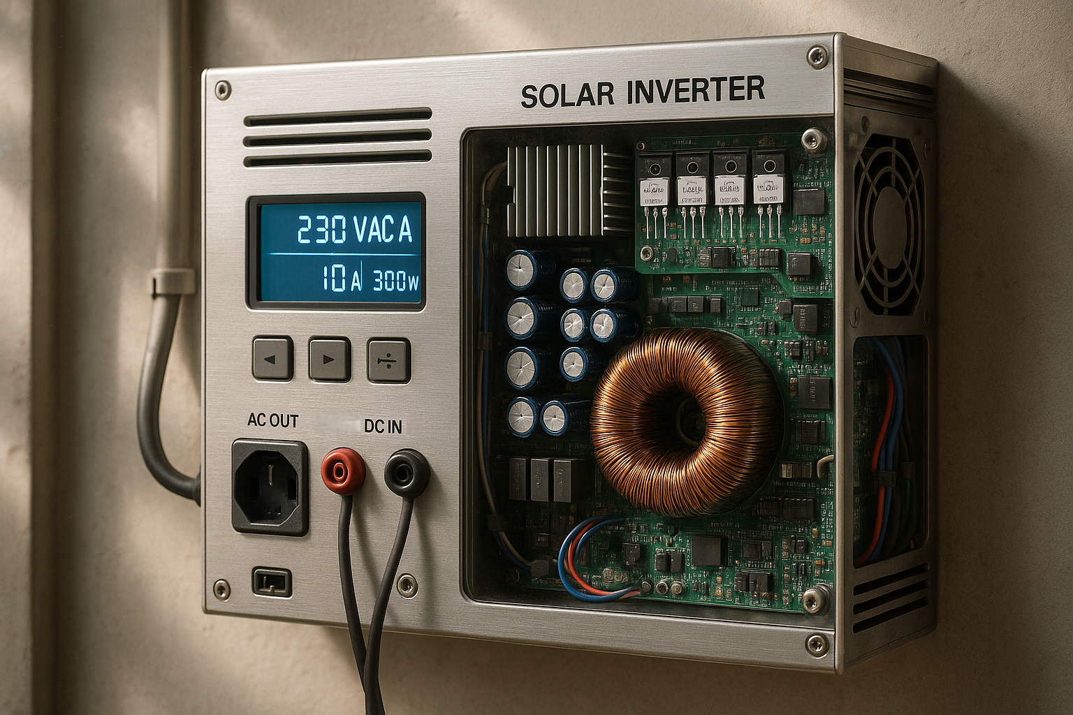
This inverter will operate smoothly using IGBTs (like IKP20N60T: rated 40A, 600V), where each IGBT in the H-bridge might drop approximately. 1.5V each at 10A (15W loss) compared to MOSFET loosing 3x – 4x conduction loss at 600V operation. Many commercial inverters use IGBT to drive high-torque, high-voltage motors and run cool, comfortably in TO-220 packages.
Electric Welding Machine
Many DIY welding machines or plasma cutters involve a circuit that converts higher (mains) VAC to lower VAC at higher current. A DIY homemade welding machine can optimally use an IGBT (such as IXFN48N50U2 or similarly rated 500V, 50A IGBT) to handle 50-100A current at approx. 300VDC with robust performance.
Although MOSFETs at 20 kHz switch fine, at ~320 V DC and 100 A, the efficiency and reliability of IGBTs make them better suited for the application.
High Power Induction Heating
Induction heating circuit utilizes resonant tanks operating at 20-100kHz. High-power induction heaters operating at 170V AC mains or higher to heat the sizable metal plates can utilize IGBTs.
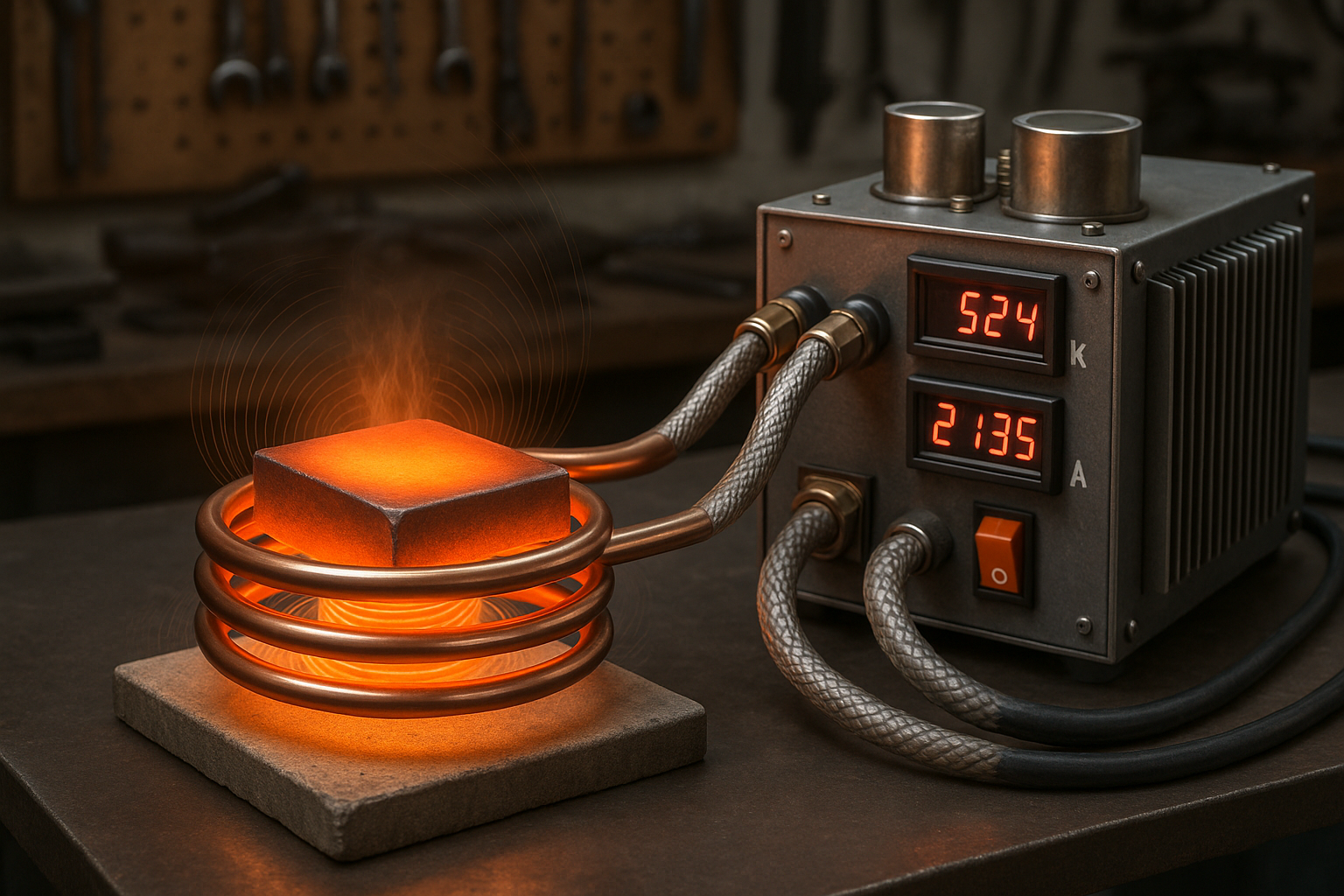
An induction heater operating at said 170V rectified AC can use 120A, 650V IGBT (FGA60N65SMD) to achieve several kilowatts of heating power. DIYers have experimented and found that pushing MOSFETs to that power leads to failures, whereas IGBTs in TO-247 packages can comfortably run the heater with proper gate drive and cooling
These examples show that IGBTs become better suited in comparison of MOSFET vs. IGBT, in high-voltage, high-power situations, commonly at the hobbyist level.
Practical Tips for Hobbyists
Although the guide above already provides many practical and numerical considerations, we offer additional tips below from hands-on experience for Electronics hobby projects working with MOSFETs or IGBTs.
Gate Driver Selection in MOSFET vs. IGBT
If your DIY electronics project uses MOSFETs, you can often drive the gate directly from a microcontroller using a resistor—this works well, especially for logic-level MOSFETs at lower frequencies.
For IGBTs, however, it’s best to use a dedicated gate driver that can provide around +15 V when on and -5 V when off. Many standard gate driver chips, like the FAN7388 or IR2110, are well-suited for driving both MOSFETs and IGBTs in half-bridge circuits.
Parallel & Series Connections of MOSFET vs. IGBT
Both MOSFETs and IGBTs can be paralleled when in need of more current handling. Observe caution when paralleling the MOSFETs, making sure they share the gate drive and each MOSFET has a small current balancing source resistor.
To parallel IGBTS, however, more caution is needed. They need to turn ON/OFF simultaneously, which indirectly means the value of the small gate resistor may matter more than you think.
We do not recommend adding MOSFETs or IGBTs in series (to achieve higher voltage handling) because balancing both timing and voltage becomes more difficult.
Thermal Management of MOSFET vs. IGBT
Both IGBTs and MOSFETs will need heat sinks in electronics hobby projects for efficient, optimal performance when operating at high power.
When designing your project, pass your circuit through a stress test and measure the heat at peak operation. If the temperature is reaching 80 °C, consider using a bigger heat sink or implementing active cooling for optimal operation. Note that MOSFETs have higher derating compared to IGBTs; therefore, to prolong MOSFET’s life and performance, implement better active cooling with MOSFET application.
Conclusion
Choosing between MOSFET vs. IGBT can make all the difference in bringing your DIY electronics project to life. You will find MOSFETs are often the best fit. This is true when you work with lower voltages. It also applies to higher frequencies. Consider Arduino gadgets, for example. Computer power supplies are another instance. MOSFETs operate efficiently in these cases. They are also easy to use.
On the other hand, IGBTs really shine in high-voltage, high-power scenarios. IGBTs handle demanding projects. Consider inverters or induction heaters. Electric vehicle chargers are another example. IGBTs offer superior power. They also provide more reliability. MOSFETs alone cannot match this.
Understanding where each device excels helps you pick the right tool for the job, setting your project up for success.