A voltage divider law explains how a simple resistor divider converts an input voltage into a predictable, lower output voltage.
If you have ever searched for the Vout formula, this is the core relationship behind it: two resistors in series, with the output taken as a fixed fraction of Vin based on their ratio.
Engineers rely on voltage divider circuits every day for practical tasks such as signal scaling, setting reference and bias voltages, and interfacing higher-voltage signals with sensitive inputs like microcontroller ADCs.
You will find voltage dividers everywhere from sensor front-ends and feedback networks to logic-level shifting between 5 V and 3.3 V systems.
However, real-world circuits are rarely ideal. The moment you connect a load to the divider output, the voltage can shift from its expected value.
This is where many designs fail quietly. Understanding the loaded voltage divider is just as important as memorizing the basic formula.
In this article, you will learn:
- What a voltage divider is and how it works
- The ideal voltage divider law and Vout formula
- How to select resistor values for a target output voltage
- Why loading affects Vout and how to calculate it correctly
- Practical worked examples, common mistakes, and design checks
- When a voltage divider is appropriate and when it is not
By the end, you will be able to design and analyze voltage divider circuits with confidence, avoiding the common pitfalls that cause inaccurate readings or unstable outputs in real electronic systems.
What Is a Voltage Divider?
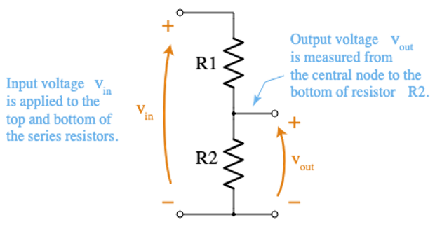
A voltage divider (also called a resistor divider) is two (or more) resistors connected in series across an input voltage Vin, without Vout taken from a node between them.
The key idea is simple: in a series path, the same current flows through every resistor. That means the input voltage is split into drops that are proportional to resistance. In the common two-resistor diagram:
- R1 is the “top” resistor (from Vin to the output node)
- R2 is the “bottom” resistor (from the output node to ground)
- Vout is measured across R2 (node-to-ground)
In series circuits, the same current flows through each resistor, which is why the voltage divider works as expected.
In contrast, parallel circuits split current instead of voltage, which is explained in our current divider formula guide.
Voltage Divider Law
For an ideal two-resistor voltage divider with no load connected to the output node, the output voltage is given by:
\[ V_{out} = V_{in} \cdot \frac{R_2}{R_1 + R_2} \]
This is the most-used voltage divider formula in electronics. It shows that the output voltage depends only on the ratio of the resistors, not on their absolute values.
If both resistors are scaled up or down by the same factor, the output voltage remains unchanged. The reason this works is simple. Because R1 and R2 are in series, the same current flows through both.
The total resistance seen by the source is R1+R2, so the circuit current is:
\[ I = \frac{V_{in}}{R_1 + R_2} \]
The output voltage is the voltage drop across R2:
\[ V_{out} = I \cdot R_2 \]
Substituting the current expression gives the standard divider equation.
Ratio Effects
You can think of the input voltage as being “shared” between the two resistors. The larger a resistor is, the larger the voltage drop across it.
- If R1=R2 the voltage splits evenly, so Vout = Vin /2
- If R2 is larger than R1, more voltage appears across R2 and Vout moves closer to Vin.
- If R2 is smaller than R1, only a small portion of the voltage appears at the output.
A good rule of thumb is that the output voltage “follows” the larger resistor. This equation is called ideal because it is only accurate under specific conditions.
Assumptions Behind the Ideal Equation
The output must be effectively unloaded, meaning no significant current is drawn from the divider. In practice, this means the load impedance should be much higher than R2, such as an ADC input or an op-amp input.
It also assumes the resistors behave ideally: they are linear, within tolerance, and unaffected by temperature or power dissipation. Finally, it applies to DC or steady-state resistive conditions.
For AC signals, resistors are replaced by impedances, and the same ratio concept applies using complex values.
In real designs, absolute resistor values still matter. Very low values waste power, while very high values increase noise sensitivity and loading errors.
For most signal-level applications, resistor values in the range of a few kilohms to tens of kilohms provide a good balance.
How to Choose R1 and R2 for a Target Vout

A practical way to design a voltage divider is to start with the ratio, not the absolute resistor values. First define the fraction of the input voltage you want at the output:
\[ f = \frac{V_{out}}{V_{in}} \]
From the ideal voltage divider law, the resistor ratio that produces this fraction is:
\[ \frac{R_2}{R_1} = \frac{f}{1-f} \]
This form is especially useful in real designs because it gives you flexibility. Once the ratio is known, you can:
- Pick a convenient standard value for one resistor
- Calculate the other resistor directly from the ratio
- Adjust both values together later without changing Vout
A few quick intuition examples:
- f=0.5 → R2=R1 → output is half of the input
- f<0.5 → R2<R1 → output is a smaller fraction of Vin
- f>0.5 > → R2>R1 → output moves closer to Vin
While the ratio sets the output voltage, the absolute resistor values control real-world behavior.
Choosing Absolute Resistor Values
If the resistor values are too low (small ohmic values):
- Unnecessary current is drawn from the source
- Power dissipation increases
- Resistors and upstream circuitry may heat up
- The divider can load and disturb the signal source
If the resistor values are too high (hundreds of kilohms to megaohms):
- The output node becomes high impedance
- Noise pickup becomes more likely
- Leakage currents start to matter
- ADC readings can become unstable or inaccurate
A common engineering guideline is:
- Choose the divider current to be comfortably higher than any expected leakage or bias current at the output node
- This keeps the voltage ratio stable across temperature and operating conditions
ADC and Input Loading Considerations
When the divider drives an ADC input, source impedance needs extra attention:
- Many ADCs momentarily draw current during sampling
- High divider impedance can cause the sampled voltage to droop
- This shows up as conversion error or jitter
Typical solutions are:
- Keep divider resistance within the ADC’s recommended source impedance range
- Or add a small capacitor from the ADC pin to ground to act as a local charge reservoir (datasheet-dependent)
In practice, the workflow is simple: design the ratio to hit your target voltage first, then select resistor values that balance power consumption, noise immunity, and the requirements of the circuit connected to the output.
Loaded Voltage Divider

In real circuits, the output of a voltage divider is rarely unloaded. Any circuit connected to Vout draws current.
Electrically, this load appears in parallel with R2, which reduces the effective resistance and causes the output voltage to drop. This effect is called loading.
Key effects of loading:
- The load draws current from the divider
- The effective bottom resistance decreases
- The divider ratio changes
- Vout is lower than the ideal value
If a load resistor RL is connected from Vout to ground, first compute the parallel combination:
\[ R_{bot} = R_2 \parallel R_L = \frac{R_2R_L}{R_2 + R_L} \]
Then use the divider equation with this new bottom resistance:
\[ V_{out,\;loaded} = V_{in}\cdot \frac{R_2 \parallel R_L}{R_1 + (R_2 \parallel R_L)} \]
Because R2 ∥ RL< R2, the output voltage is always lower than the ideal divider prediction.
A clean way to understand this behavior is with the Thévenin equivalent. The divider can be replaced by a voltage source and a series resistance:
\[ V_{th} = V_{in}\cdot \frac{R_2}{R_1 + R_2} \]
\[ R_{th} = R_1 \parallel R_2 \]
From the load’s point of view, the divider is a non-ideal voltage source. The load forms another divider with the internal resistance:
\[ V_{out} = V_{th}\cdot \frac{R_L}{R_{th} + R_L} \]
This directly explains the voltage droop:
- Smaller RL causes more drop
- Larger RL preserves the ideal voltage
In practice, loading is considered negligible when:
- RL≫R2 (rule of thumb: 10× or more)
- The resulting voltage error is within the allowed tolerance (1%, 5%, etc.)
If these conditions are not met, the divider must be treated as loaded, or the output should be buffered with a voltage follower or op-amp.
Worked Examples
Example 1 — Basic Vout calculation
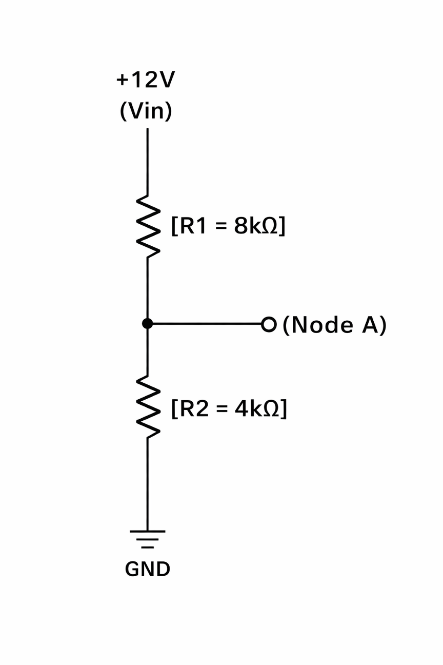
Given
\[ V_{in} = 12V \]
\[ R_1 = 8k\Omega \]
\[ R_2 = 4k\Omega \]
Output voltage
\[ V_{out} = V_{in}\cdot \frac{R_2}{R_1 + R_2} \]
\[ V_{out} = 12\cdot \frac{4k}{8k+4k} = 12\cdot \frac{4}{12} = 4V \]
Total resistance:
\[ R_T = R_1 + R_2 = 8k + 4k = 12k\Omega \]
Current:
\[ I = \frac{V_{in}}{R_T} = \frac{12}{12k} = 1mA \]
Power check
\[ P_1 = I^2R_1 = (1mA)^2\cdot 8k = 8mW \]
\[ P_2 = I^2R_2 = (1mA)^2\cdot 4k = 4mW \]
These are well within a typical 1/4W resistor rating.
Example 2 — Loaded divider (ideal vs real Vout)
Given
- Same divider as Example 1
- Load: RL=12kΩ from Vout to ground
Step 1: Combine R2 and RL in parallel
\[ R_2 \parallel R_L = \frac{R_2 R_L}{R_2 + R_L} \]
\[ R_2 \parallel R_L = \frac{(4k)(12k)}{4k + 12k} = \frac{48}{16}k = 3k\Omega \]
Step 2: Use the loaded divider equation
\[ V_{out,\;loaded} = V_{in}\cdot \frac{R_2 \parallel R_L}{R_1 + (R_2 \parallel R_L)} \]
\[ V_{out,\;loaded} = 12\cdot \frac{3k}{8k + 3k} = 12\cdot \frac{3}{11} = 3.27V \]
Compare
- Ideal (unloaded): 4.00V
- Loaded: 3.27V
Drop and error
\[ \Delta V = 4.00 – 3.27 = 0.73V \]
Percent low:
\[ \%\;low = \frac{0.73}{4.00}\times 100 \approx 18.25\% \]
So the load makes the divider read about 18% low, which is why loading is usually the #1 real-world divider mistake.
Example 3 — Choose R values for a target Vout
Given
\[ V_{in} = 9V \]
\[ V_{out} = 5V \]
Step 1: Compute the fraction
\[ f = \frac{V_{out}}{V_{in}} = \frac{5}{9} = 0.556 \]
Step 2: Compute the resistor ratio
\[ \frac{R_2}{R_1} = \frac{f}{1-f} \]
\[ \frac{R_2}{R_1} = \frac{0.556}{1-0.556} = \frac{0.556}{0.444} = 1.25 \]
So you want R2≈1.25R1.
Pick standard values (examples)
Option A:
\[ \frac{R_2}{R_1} = \frac{10k\Omega}{8k\Omega} = 1.25 \]
Option B:
\[ \frac{R_2}{R_1} = \frac{20k\Omega}{16k\Omega} = 1.25 \]
Quick verify
\[ V_{out} = V_{in}\cdot \frac{R_2}{R_1 + R_2} = 9\cdot \frac{10}{8+10} = 9\cdot \frac{10}{18} = 5V \]
If you need fine tuning:
- Use the nearest E-series pair and verify
- Or replace one resistor with a small trim potentiometer (then lock it after calibration)

Voltage Divider in AC Circuits (Impedance Form)
For AC signals, the voltage divider law stays the same, but resistances are replaced by impedances:
\[ V_{out} = V_{in}\cdot \frac{Z_2}{Z_1 + Z_2} \]
Here, Z1 and Z2 can be resistive, capacitive, inductive, or any combination. Because impedance is generally complex, the output voltage can change in both magnitude and phase as frequency changes.
This is why many basic filters are just frequency-dependent voltage dividers:
- RC divider → low-pass or high-pass behavior
- RL divider → frequency-selective attenuation and phase shift
At low frequencies, capacitive impedance is high and inductive impedance is low. At high frequencies, the opposite is true. As a result, the divider ratio becomes frequency-dependent instead of fixed.
The key idea is simple: AC voltage dividers follow the same math as DC dividers, but impedance replaces resistance.
Common mistakes to avoid
- Swapping R1 and R2. Vout is always taken across the bottom element (the one connected to ground).
- Ignoring load or input impedance: ADC inputs, sensor inputs, bias networks, and amplifier inputs still load the divider and change the effective impedance.
- Trying to power a load with a divider: Voltage dividers are for signals and references, not for delivering power. If you need real output current, use a linear regulator or a DC-DC converter instead of a resistor divider.
- Choosing extreme resistor values
- Too low → wasted power and unnecessary heat
- Too high → noise sensitivity, leakage errors, and unstable readings
- Too low → wasted power and unnecessary heat
Used correctly, impedance-based voltage dividers are the foundation of filters, bias networks, and signal conditioning.
Used incorrectly, they are a common source of amplitude errors, phase errors, and unstable measurements.
Final Thoughts
The voltage divider law is one of the most useful shortcuts in electronics: it gives you the Vout formula immediately for a two-resistor resistor divider.
In real designs, the section that matters most is the loaded voltage divider, because any finite load changes the divider ratio and pulls Vout down.
If you take only three habits from this guide:
- Confirm the network is truly a series divider and identify where Vout is measured.
- Check loading by replacing R2 with R2 ∥ RL when needed.
- Do a quick current and power sanity check so the divider is stable and safe.
If you are building dividers often, it helps to have standard resistor values on hand (resistor categories and networks), an adjustable trimmer for tuning, and a simple buffer/reference option when accuracy matters.
Choosing the right resistors is just as important as applying the voltage divider law correctly. In real designs, engineers select components based on tolerance, power rating, package type, and layout constraints.
Flywing Tech stocks resistors and voltage monitoring parts. We cover a wide range of resistor catalog including surface-mount chip resistors, through-hole resistors, resistor networks, and chassis-mount resistors.
FAQ – Voltage Divider Law
1) What is the voltage divider law used for in real circuits?
The voltage divider law is used to scale voltages, set reference and bias levels, and interface higher-voltage signals with lower-voltage inputs such as microcontroller ADCs, sensors, and comparators.
2) What is the standard voltage divider equation?
For an ideal two-resistor divider with no load, the output voltage is calculated as:
\[ V_{out} = V_{in} \cdot \frac{R_2}{R_1 + R_2} \]
The output depends only on the resistor ratio, not their absolute values.
3) Why does the voltage divider law fail in real circuits?
The law assumes the output is unloaded. In real circuits, the connected load draws current and appears in parallel with the bottom resistor, changing the divider ratio and reducing Vout.
4) What is a loaded voltage divider?
A loaded voltage divider is one where the output drives a real load. The load resistance combines with the bottom resistor in parallel, lowering the effective resistance and pulling the output voltage down.
5) How do I calculate Vout for a loaded voltage divider?
First replace the bottom resistor with its parallel combination with the load:
\[ R_{bot} = R_2 \parallel R_L = \frac{R_2R_L}{R_2 + R_L} \]
Then use the divider equation with the new resistance:
\[ V_{out,\;loaded} = V_{in}\cdot \frac{R_2 \parallel R_L}{R_1 + (R_2 \parallel R_L)} \]
6) When can loading be ignored safely?
Loading is usually negligible when the load resistance is at least 10× higher than the bottom divider resistor and the resulting voltage error is within your acceptable tolerance (for example 1% or 5%).
7) Can I use a voltage divider directly with an ADC input?
Yes, but you must consider ADC input impedance and sampling behavior. High divider resistance can cause sampling droop. Many designs either lower the divider resistance or add a small capacitor at the ADC pin for stability.
8) Why shouldn’t I power a device using a voltage divider?
Voltage dividers cannot regulate voltage under changing load current. As the load current varies, Vout shifts. For powering devices, always use a linear regulator or a DC-DC converter.
9) Does the voltage divider law work for AC signals?
Yes, but resistors must be replaced with impedances:
\[ V_{out} = V_{in}\cdot \frac{Z_2}{Z_1 + Z_2} \]
Because impedance is frequency-dependent, both amplitude and phase of Vout can change with frequency.
10) What resistor values should I choose for a stable divider?
Typical signal dividers use resistor values in the 1 kΩ to 100 kΩ range. Very low values waste power, while very high values increase noise sensitivity and loading errors. Choose values based on power, noise, and input impedance requirements.
11) How do I prevent voltage divider errors in precision designs?
Use tight-tolerance resistors (1% or better), check loading effects, perform current and power sanity checks, and buffer the output with an op-amp follower if accuracy matters.
12) What is the most common voltage divider mistake?
The most common mistake is ignoring loading and assuming the ideal divider equation still applies after connecting a real load.