Introduction
TIP122 is a Darlington power transistor widely used in electronic applications, including motor control, high-current switching, high amplification, relay drivers, and power supply circuits. TIP122 Darlington pair can easily handle medium to high current loads. Therefore, it is one of the popular choice for design professionals and electrical engineering enthusiasts.
The TIP122 transistor essentially combines two NPN transistors into a single package, creating a Darlington pair. The small base current on the base of this Darlington can control a large current at the collector. Its ability to control a large collector current (up to 5 amps) makes it suitable for applications that require interfacing with microcontrollers, such as motor control, relay circuits, solenoids, and high-current power supplies.
The Darlington TIP122 combines two bipolar transistors that offer high DC current gain up to thousands, and provide continuous collector current up to 5 amperes. It also offers a wide voltage collector-to-emitter voltage of up to 100V DC. Different variants of TIP122 have varying collector currents and collector-to-emitter (VCE) voltages. For example, TIP120 has a collector to emitter (VCE) up to 60 volts, and TIP121 has a VCE up to 80 volts. So, different variants of TIP transistors have different VCE and collector current ranges. Therefore, you should always check the datasheet for accurate and exact device limits.
What is TIP122 and Why Do We Use it?
TIP122 is a powerful Darlington transistor that is primarily use for medium to high switching and amplification applications. Its large collector current and wide collector to emitter voltage range make it perfect for medium to high current applications.
A Darlington pair is a transistor that combines two bipolar junction transistors to achieve high current gain, resulting in a small input base current able to control the large output collector current. Therefore, the TIP122 transistor is among the most frequently use in applications that require interfacing with microcontrollers, Arduino, and Raspberry Pi, such as motor control, relay drivers, and sensor interfacing.
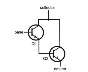
A Darlington pair, such as TIP122, consists of two bipolar transistors such that the first transistor amplifies the base current. The output of the first transistor Q1 (emitter terminal) will become the input (base terminal) for the second transistor Q2. The collector terminals of both transistors are tied together as shown in the basic circuit diagram below. This type of configuration of two bipolar junction transistors is known as the Darlington pair.
Why Do we Use it?
The emitter current of Q1 will become the base current of Q2, and the current gain of both transistors, Q1 and Q2, will multiply to make the large DC current gain. Therefore, the main advantage of using this Darlington configuration is that it offers high current gain (β).
\[ \beta_{\text{total}} = \beta_{1} \times \beta_{2} \]
For example, if the current gain of Q1 is 100 and the current gain of Q2 is also 100. The cumulative gain of a transistor when use in a Darlington configuration will become;
\[
\beta_{\text{total}} = 100 \times 100
\]
\[
\beta_{\text{total}} = 10{,}000
\]
Its simple design, high DC current gain, wide collector to emitter voltage range, and large output current handling capability of up to 5 amperes, make it a perfect device to use in most electronic applications such as motor PWM control, solenoids, LED dimmers, sensors interfacing with microcontrollers, and actuator circuits. Apart from these, it is also cost-effective and only consists of three terminals, i.e., emitter, collector, and base.
TIP122 PIN Configuration
TIP122 has a simple design and consists of three pins. It mostly comes in a TO-220 package and is manufactured by STMicroelectronics and Texas Instruments. It is a high current gain transistor and therefore requires a heatsink for high current handling applications. The TIP122 transistor has three terminals known as base (B), Emitter (E), and Collector (C).
Pin Configuration of TIP122 Transistor

TIP122 Internal Working and Characteristics
TIP122 Darlington transistor offers high current gain and current amplification. The Darlington pair consists of two transistors connected in such a way that the output of the first transistor becomes the input of the second transistor. Its high current and amplification capability make it suitable for high switching and amplification applications. However, understanding the TIP122 internal circuit and its working operation is essential for design engineers and electrical enthusiasts to know how it efficiently achieves high current gain.
Internal Working of TIP122
The internal circuit of TIP122 consists of a Darlington pair, i.e., two bipolar junction transistors. These two transistors, Q1 and Q2, are connected such that the output of transistor Q1 (emitter terminal) acts as an input signal to the base terminal of transistor Q2. The collectors of both transistors are combined. The collector terminal provides the output current that drives the load. This configuration known as the Darlington pair, allows the transistors to act as a single transistor and provide a cumulative gain that is the product of the individual gains of both transistors.
The working flow of TIP122 goes: the Q1 receives the input signal at the base terminal. The base signal is amplified with a current gain of β1. The output of the Q1 will become the input signal of the Q2 transistor. The amplified input signal of Q2 is further amplified with a current gain of β2. The overall gain of Darlington is found by multiplying the individual gains of both transistors.
Therefore, when we apply a small base current at the base terminal, it controls the large current at the output terminal due to the high current gain of TIP122. Thus, TIP122 provides a high current gain and wide collector to emitter voltage that is suitable for a wide range of applications, including motor drive, relay circuits, and solenoids.
Technical Specifications & Parameters
There are a lot of variants of Darlington pair transistors available, and one such transistor is TIP122. Every variant has different technical specifications and parameters. Engineers and designers need to understand and grasp the core technical specifications of TIP122 to efficiently design applications as per the defined upper and lower limits.
Technical Specifications of TIP122 Transistor

Circuit Design with TIP122
Designing the circuit with a TIP122 Darlington transistor is straightforward because it only consists of three terminals. TIP122’s ability to drive high current loads, such as motors and relays, using a small current signal, makes it perfect for interfacing with microcontrollers and Arduino boards. In this section, I will explain how to design a circuit with TIP122 that includes its biasing, load connection, base resistor calculation, and heat management considerations.
In typical applications, the base terminal is usually the input terminal, and we connect it with the GPIO of the microcontroller using a base resistor. The collector terminal is the output terminal, and we connect it with a load such as a motor, relay, or solenoid. The emitter terminal acts as the common GND for the circuit. However, a step-by-step guide is essential to efficiently design the specific application circuit with the TIP122 transistor.
Select the Load
The most important step in designing the circuit with TIP122 is the identification of the load. For example, motor, relay, or coil, etc. By determining the type of load, you will be able to identify the output current requirement of your circuit. The TIP122 maximum provides 5 amperes of current. Therefore, ensure that your application load current should be below 5A for safe and smooth operation.
Base resistor calculation
The base resistor is essential because it controls the current entering the TIP122 base. With appropriate base resistance, it ensures that the transistor does not overdrive and also ensures that it is in saturation mode. The formula to calculate the base resistance is;
\[
R_b = \frac{V_{in} – V_{be}}{I_b}
\]
Where Vin is the control input voltage, e.g., from Arduino, VBE is the 2V, and ib is
\[
I_b = \frac{I_c}{\beta}
\]
For example, to drive a motor of 12V and 2A, the base resistor value will be;
\[
I_b = \frac{I_c}{\beta}
\]
\[
I_b = \frac{2\text{A}}{500} = 0.004\text{A} = 4\text{mA}
\]
\[
R_b = \frac{V_{in} – V_{be}}{I_b}
\]
\[
R_b = \frac{5\text{V} – 2\text{V}}{0.004\text{A}} = 750\,\Omega
\]
Flyback diode protection
When using inductive loads as the output, such as motors and coils, always connect the flyback diode, like 1N4007, to protect the TIP122 from high voltage spikes generated from inductive loads.
Power dissipation and heat sink
TIP122 can easily handle 65 watts of power. However, without a heatsink, it can overheat and damage the device. Therefore, it is recommended to use a TO-220 heatsink when dealing with the TIP122 transistor.
Common Circuit Applications with TIP122 Darlington Transistor
TIP122 is a powerful Darlington pair transistor that is famous for its high current gain and switching efficiency. In this section, I have included four common circuit applications using the TIP122 transistor. All these application circuits are demonstrated using the Proteus software.
Auto LED Dimmer Circuit Using TIP122
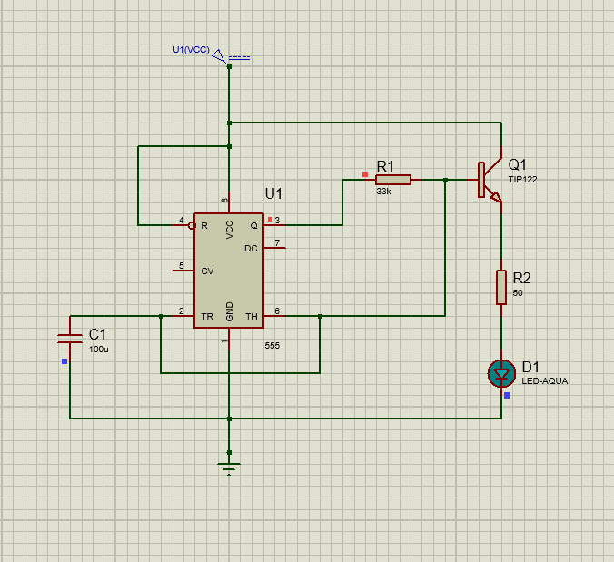
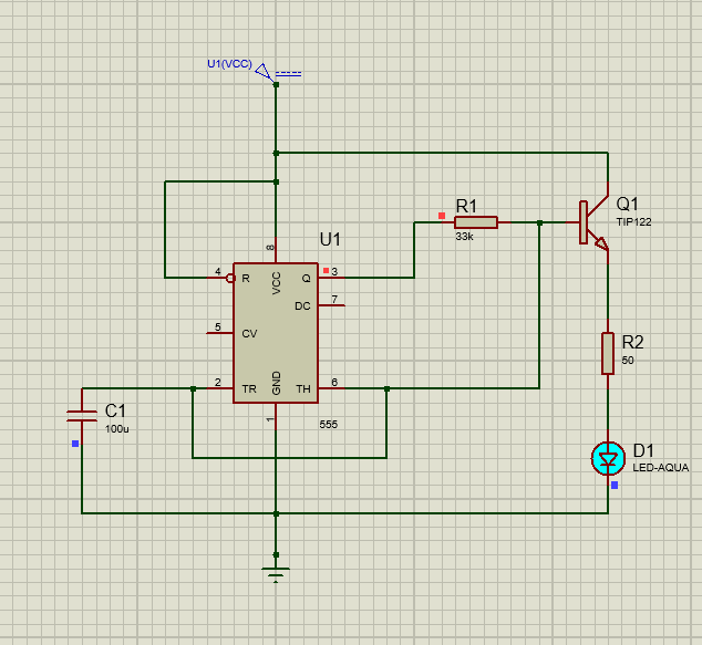
One simple and useful application circuit that can be built using TIP122 is an LED dimmer circuit. The LED dimmer circuit allows you to control the brightness of the LED using PWM. The dimmer circuit consists of a 555 timer IC, a resistor, an LED, and one TIP122 transistor.
The 555 timer IC generates the continuous square waveform at pin 3. The PWM is use as an input to the base terminal of TIP122 using a resistance of 33KΩ. The timing capacitor of 100uF continuously charges and discharges, thus generating the varying duty cycle.
When the capacitor charges, the duty cycle also increases, resulting in an increase in the ON time compared to the OFF time of PWM. This makes the LED glow brighter with the increase in ON time.
However, when the capacitor discharges, the duty cycle decreases, resulting in a decrease in the ON time compared to the OFF time of PWM. This makes the LED slowly fade with a decrease in ON time, as shown in the circuit diagram below.
DC Motor Speed & Direction Control with PWM Using TIP122
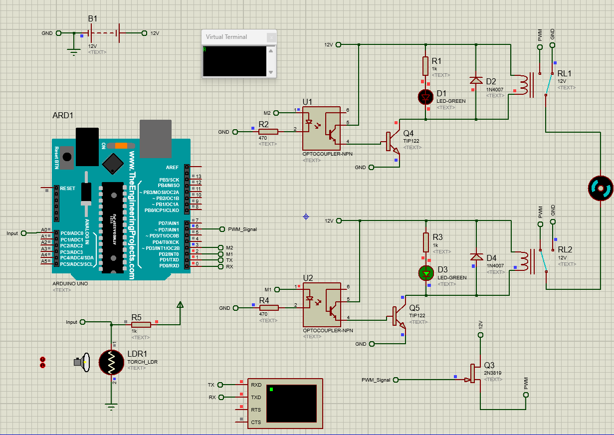
TIP122 is a powerful Darlington pair that can provide high current gain and collector current up to 5 amperes. Therefore, it is suitable for applications that require interfacing with a microcontroller or Arduino. Once such an application is a DC motor speed control using varying PWM with a Light Dependent Resistor (LDR). The Arduino provides a low current signal that is used at the base terminal of TIP122, and it provides a high current that can easily drive the DC motor.
Speed & Direction Control Mechanism
In this application, TIP122 is use as a motor driver, Arduino as the controller, and LDR as a light sensor. In the daylight, the LDR shows low resistance, and in the darkness, the LDR generates high resistance. The LDR is use along with a resistor (R5) to form a voltage divider network. This pin is then connected to the Arduino pin A0. The Arduino continuously monitors the voltage on this pin and then converts it into the PWM signal. This PWM signal is output through pin 6 of the Arduino as shown in the circuit diagram.
The output PWM from Arduino is passed through he optocouplers acting as the isolation between Arduino and the TIP122 transistor. The transistors TIP122 receive a signal from the optocouplers and, as a result, turn ON or OFF the relays. The ON/OFF sequence of both relays (RL1 and RL2) decides the direction of the motor.
Motor Direction Control using RL1 and RL2
</p>
<!-- wp:preformatted -->
<pre class="wp-block-preformatted">int Motor1 = 2;
int Motor2 = 3;
int PWMControl= 6;
int PWM_Input = A0;
int PWM_Value = 0;
void setup() {
  pinMode(Motor1, OUTPUT);
  pinMode(Motor2, OUTPUT);
  pinMode(PWMControl, OUTPUT);
  pinMode(PWM_Input, INPUT);
  Serial.begin(9600);
}
void loop() {
  PWM_Value = analogRead(PWM_Input);
  PWM_Value = map(PWM_Value, 0, 1023, 0, 255);
  analogWrite(PWMControl, PWM_Value);
  if(Serial.available())
  {
    char data = Serial.read();
    Serial.println(data);
    if(data == 'C'){MotorClockwise();}
    if(data == 'A'){MotorAntiClockwise();}
    if(data == 'S'){MotorStop();}

  }
}
void MotorAntiClockwise()
{
  digitalWrite(Motor1, HIGH);
  digitalWrite(Motor2, LOW);
}
void MotorClockwise()
{
  digitalWrite(Motor1, LOW);
  digitalWrite(Motor2, HIGH);
}
void MotorStop()
{
  digitalWrite(Motor1, HIGH);
  digitalWrite(Motor2, HIGH);
}</pre>
<!-- /wp:preformatted -->
<p class="has-text-align-left">
Arduino code Explanation
The Arduino code reads the analog input from the LDR and converts it to a PWM signal using this “ PWM_Value = map(PWM_Value, 0, 1023, 0, 255)“ function. Two Relays, RL1 and RL2, control the direction of motors using serial commands are A, C, and S. When the user enters A, the motor will start rotating anticlockwise, C for clockwise, and S for the motor stop command.

LED Flasher Circuit Using TIP122
The LED flasher circuit is one of the interactive circuits that can be easily built using the TIP122 transistor and a number of LEDs. This flasher circuit consists of a 555 timer IC that is responsible for generating the continuous square wave output. This square waveform is use to turn ON and OFF the LEDs, resulting in a flashing of LEDs. The circuit also consists of a shift register 74AC164 and a TIP122 transistor. The shift register is use to connect the group of LEDs to form the flashing effect.
The shift resistor sequentially shifts the logic output to glow the LEDs in a pattern. The TIP122 transistor acts as the current amplifier that drives the group of LEDs efficiently. This design is very useful in applications such as decorative lighting and automatic indicators.


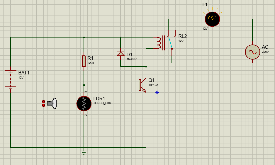
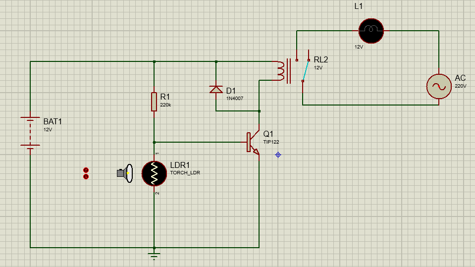
Automatic Night Light Circuit Using LDR and TIP122
Another useful application of TIP122 is an automatic night light circuit. This circuit consists of an LDR, relay, and TIP122 Darlington transistor. The LDR acts as the light sensor, and TIP122 drives the relay, and the relay is use to control the 220VAC lamp.
In daytime, the LDR shows low resistance due to the light, and therefore, the TIP122 will remain in the OFF state. However, at night, the LDR resistance increases, and this also increases the voltage at the base terminal of TIP122 using the resistor R1 (220KΩ). When the voltage at the base increases, such that it crosses the threshold, TIP122 turns ON. When the TIP122 turns ON, it energizes the relay that switches ON the AC lamp. The IN4007 diode is use for protection against back EMF. This application is widely applicable in garden lights and home gardens.
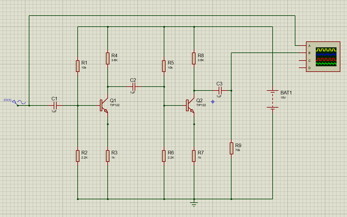
Practical Applications with Simulations: Two-Stage Audio Amplifier Circuit using TIP122
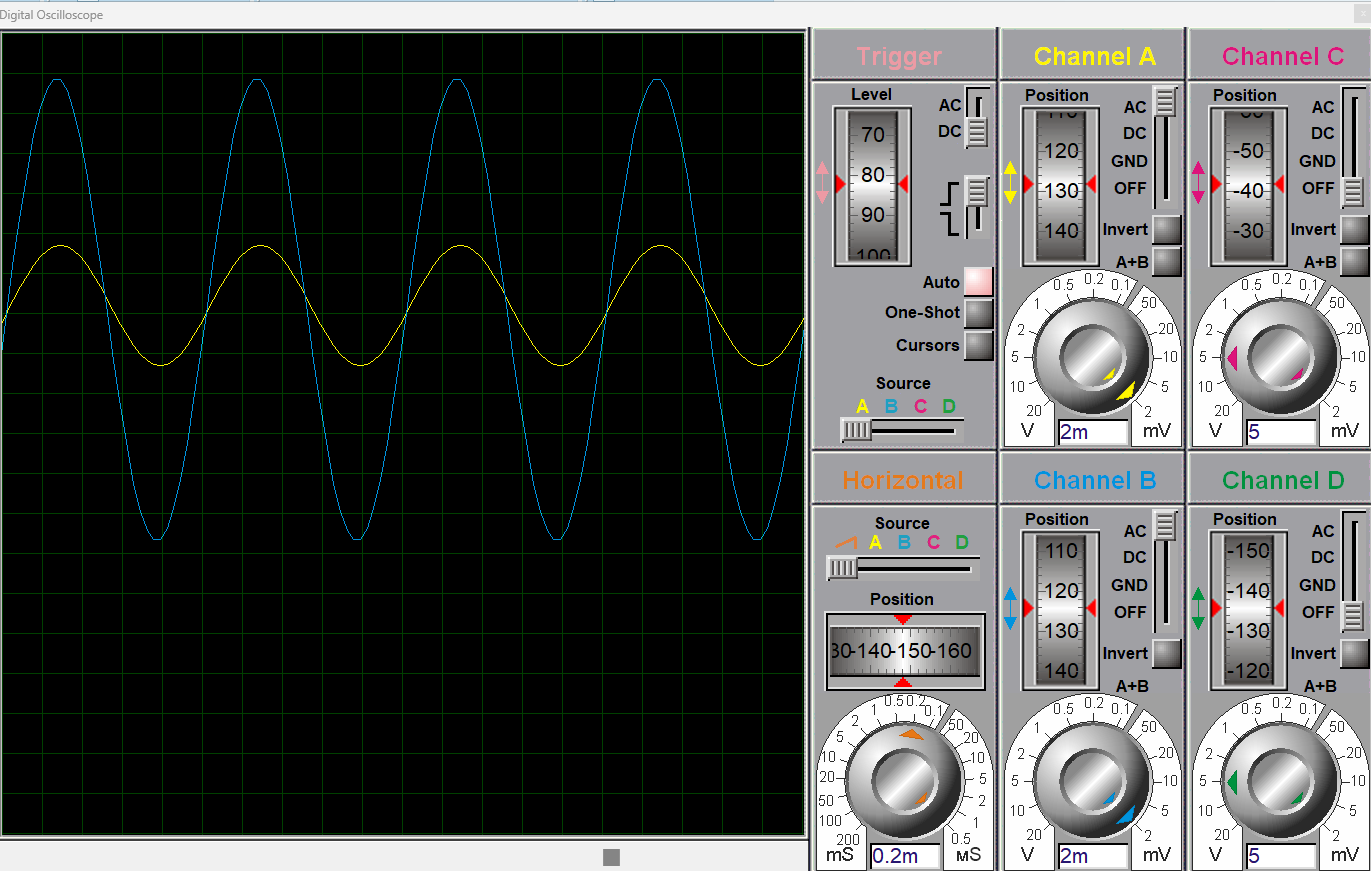
In this section, I have simulated the two-stage audio amplifier circuit using the powerful high-current gain TIP122 transistor. This audio amplifier circuit consists of two stages; the first stage amplifies the small input audio signal that can drive the next stage. The second stage further boosts the signal and finally drives the loudspeaker.
In the first stage, we apply the small audio signal of 3mV into the base terminal of TIP122 (Q1). A coupling capacitor of 1uF is also use at the input to block the DC and only allow the AC audio signal. This stage amplifies the input signal such that it can easily drive the second stage. A voltage divider configuration is use to ensure that the TIP122 will stay in the active region for signal amplification.
The output from the collector terminal of Q1 in stage one, through the coupling capacitor, is fed into the base terminal of TIP122 (Q2). The transistor Q2 amplifies the input signal such that it can easily drive the loudspeakers. This circuit is most suitable for low-power audio applications such as microphones.
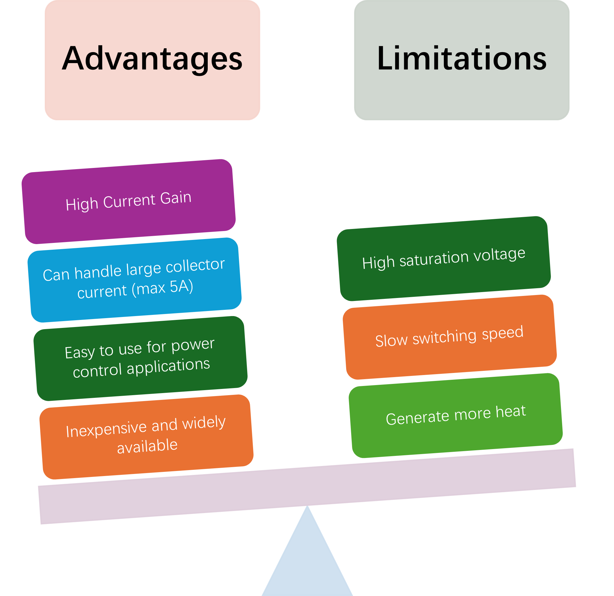
Advantages and Limitations of TIP122 Transistor
TIP122 Darlington pair is a powerful transistor that is suitable for a wide range of applications due to its high current gain and wide collector to emitter voltage. However, TIP122 has some limitations compared to its advantages, which are the topic of discussion in this section.
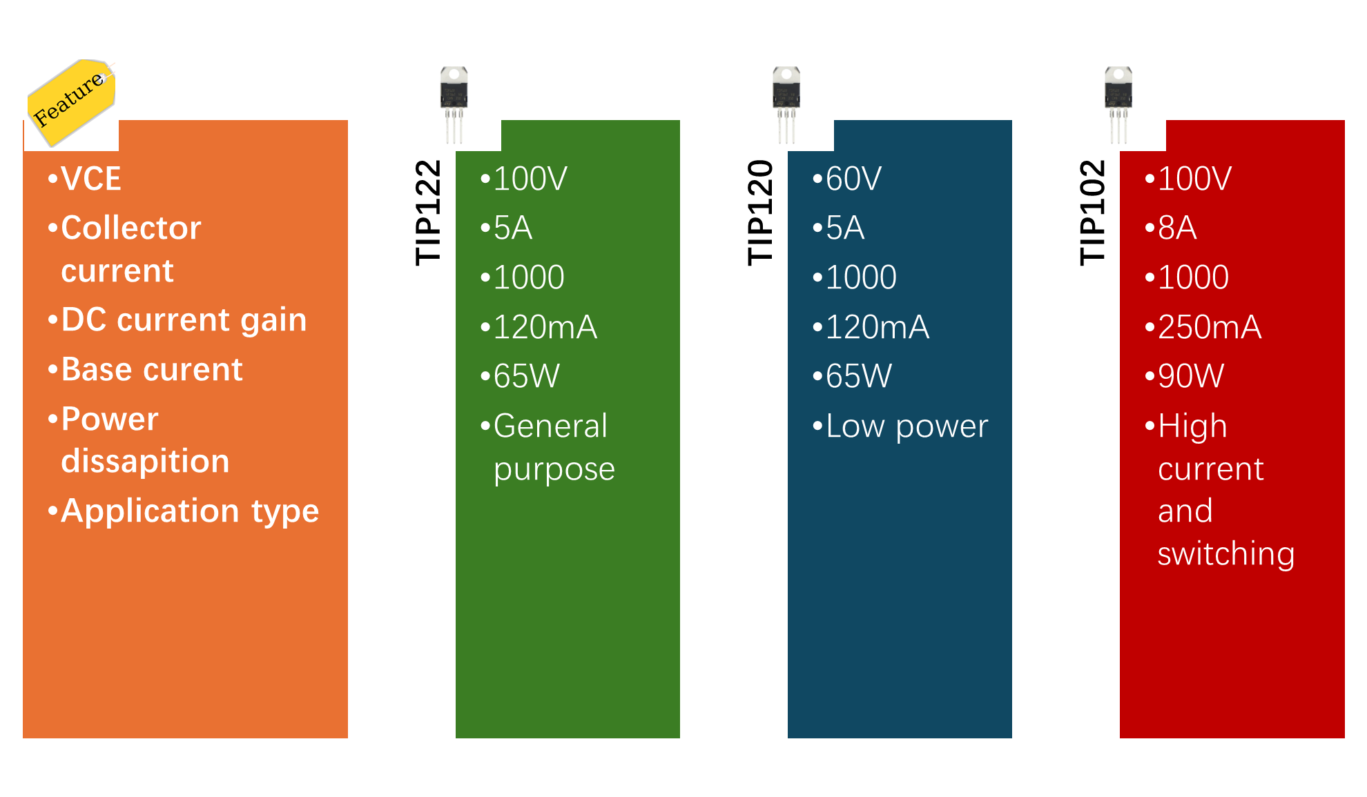
Which is Better: TIP122 VS TIP120 VS TIP102
There are other variants of the TIP122 Darlington transistor are also available in the market, such as TIP120 and TIP102. In this section, we will discuss what are the major differences between these different variants of the Darlington pair. Understanding the differences between these helps you accurately choose the best suitable transistor for your application.
Conclusion
In conclusion, TIP122 is a versatile and powerful Darlington pair transistor that offers high current gain and a wide collector-to-emitter VCE voltage. Therefore, it is widely use in switching and amplification applications such as motor control circuits, relay circuits, and interfacing devices with microcontrollers. Understanding the TIP122 circuit design, technical specifications, and function of its pinout is essential for engineers to effectively utilize it in their circuit applications. Apart from its high gain and large collector current, it has more voltage drop and heat dissipation compared to other transistor families.

Frequently Asked Questions (FAQ)
Q1. What is the maximum current TIP122 can handle?
The maximum current at the collector terminal of TIP122 is 5A to drive the loads such as motors, relays, or solenoids.
Q2. What is the difference between TIP122 and IRF7360 MOSFETs for switching?
TIP122 is for general-purpose switching and amplification applications. Whereas MOSFET switches are specifically design for efficient and faster switching applications.
Q3. Does TIP122 require a heatsink?
Yes, generally for applications that require above 1A of current heat sink is required. This will ensure smooth and efficient device operation.
Q4. What is the typical gain of TIP122?
Typically, the TIP122 transistor provides a DC current gain in the range of 1000 at 3A.
Q5. Is TIP122 an NPN or a PNP transistor?
TIP122 is an NPN transistor, and TIP127 is a PNP transistor.