Every electronics designer eventually hits the same roadblock: how do you efficiently control high current at low voltage without wasting power or overheating your circuit?
Traditional bipolar transistors drop too much voltage and burn up energy as heat, while smaller MOSFETs can’t handle heavy loads.
That’s where the IRFZ44N comes in. This N-channel MOSFET has been a go-to choice for decades because it strikes the perfect balance between high current capacity, low on-resistance, and fast switching speed.
Whether you’re building a 12 V motor driver, a DC-DC converter, or a battery management circuit, the IRFZ44N delivers the performance you need without breaking the bank.
In this article, we’ll unpack everything you need to know about the IRFZ44N transistor, from how it works and what makes it unique, to practical design tips, datasheet insights, and real-world applications.
What is IRFZ44N transistor?
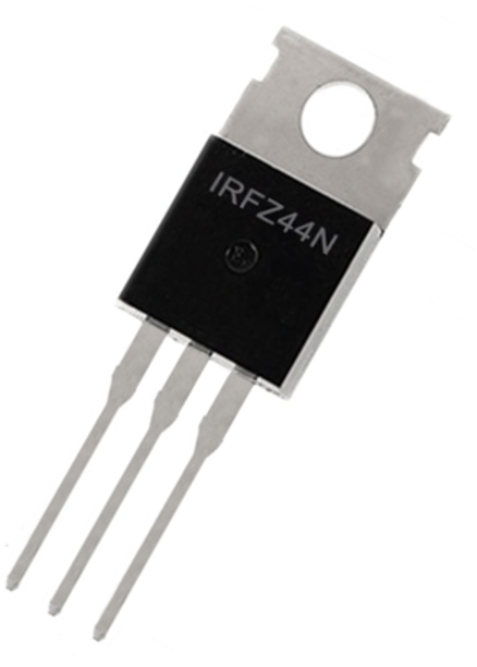
The IRFZ44N is a 55 V, 49 A N-channel enhancement-mode power MOSFET in a TO-220 package.
As an “Advanced HEXFET” device, it uses specialized processing to achieve extremely low on-resistance and fast switching with high ruggedness.
For example, at 10 A load the IRFZ44N drops only about 0.175 V on‑resistance, whereas an equivalent IGBT would drop ~1.5 V under the same conditions.
In practice the IRFZ44N begins to turn on around V_GS(th) ≈2–4 V, but requires ~10 V gate drive for full conduction.
The device is avalanche‑rated and has a built‑in body diode (from drain to source) for inductive loads. Its tab (metal back) is tied to the Drain and is designed for mounting to a heatsink to dissipate up to 94 W (at case temperature).
Pinout and Package
The IRFZ44N is usually supplied in a through-hole TO-220 case (with a metal tab) or an alternate I²PAK/TO-262 (long‑lead) variant.
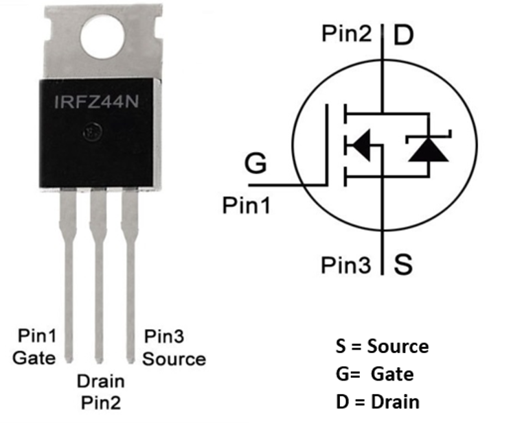
In the TO-220 package, the three leads are (looking at the front): Pin 1 = Gate (left), Pin 2 = Drain (middle, also metal tab), Pin 3 = Source (right).
| Pin No. | Pin Name | Description |
| 1 | Gate | Controls the biasing of the MOSFET |
| 2 | Drain | Current flows in through Drain |
| 3 | Source | Current flows out through Source |
The metal tab is connected to the drain and serves as a heat-sinking surface. The backside of the tab usually has a mounting hole so the MOSFET can be bolted to a heatsink or chassis.
The body‑diode (intrinsic FET diode) is oriented from source→drain (i.e. anode at Source, cathode at Drain), so it conducts when VDS is negative (driving current back into the supply).
In circuit diagrams, the IRFZ44N symbol is the standard N-channel MOSFET with the arrow (body diode) pointing from S to D.
Electrical Characteristics and Performance
To get the most out of the IRFZ44N in your design, it’s important to understand what makes it tick electrically.
Here are the key electrical characteristics that define the IRFZ44N’s performance:
- Drain–Source Voltage (VDS): The maximum voltage that can safely exist between the drain and source terminals is 55 V. Exceeding this can permanently damage the device.
- Continuous Drain Current (ID): The IRFZ44N can handle up to 49 A of continuous current under ideal conditions, though this depends on temperature and cooling.
- Gate–Source Voltage (VGS): The gate can tolerate up to ±20 V. Staying within this range is crucial to prevent gate oxide breakdown.
- Gate Threshold Voltage (VGS(th)): This is the voltage needed to begin turning the transistor on, typically between 2 V and 4 V.
- On-Resistance (RDS(on)): When fully switched on, the resistance between drain and source is around 17 mΩ, ensuring very low conduction losses.
- Total Gate Charge (Qg): About 44 nC of charge is required to switch the MOSFET on or off. This determines how powerful your gate driver needs to be for fast switching.
- Gate–Source Capacitance (CGS): Roughly 2000 pF, this capacitance influences how quickly the gate can charge or discharge.
- Power Dissipation (PD): The IRFZ44N can safely dissipate up to 94 W when the case temperature is 25 °C.
However, as the temperature rises, its capacity to handle power decreases at about 0.63 W per °C.
View the official IRFZ44N datasheet for detailed specifications and thermal characteristics.

Designing Circuits with the IRFZ44N MOSFET
When you’re designing a circuit around the IRFZ44N, the goal is to switch efficiently, stay cool, and last long.
But achieving that requires careful attention to how you drive the gate, manage heat, and handle switching transients.
1. Gate Drive
Start with the gate drive, because that’s where most designs either succeed or fail. The IRFZ44N needs a solid 10–12 V at the gate to fully turn on and achieve its low on-resistance (~17 mΩ).
If you’re driving it directly from a microcontroller, you’ll quickly find that typical logic-level outputs (3.3 V or 5 V) aren’t sufficient. In those cases, use a dedicated MOSFET driver IC such as the TC4420 or IR2110.
These drivers deliver the current needed to charge and discharge the gate capacitance quickly, ensuring sharp switching edges and minimal power loss. Adding a small gate resistor (10–100 Ω) in series can also help reduce oscillations and protect the gate from voltage spikes.
2. Thermal Management
Thermal management is often underestimated. Even with a low RDS(on), the IRFZ44N can heat up quickly under heavy current loads.
A simple rule: if your circuit handles more than a few amps continuously, use a heatsink or mount the MOSFET to a metal surface. Applying thermal paste or a silicone pad between the transistor and the heatsink improves heat transfer and boosts reliability.
If your design requires stronger mechanical stability and better thermal dissipation, consider the IRFZ44NL, a TO-262 long-lead variant.
3. Handling Inductive Loads
When switching inductive loads like motors, solenoids, or relays, sudden changes in current can cause voltage spikes that exceed the MOSFET’s 55 V rating.
To prevent damage, always include a flyback diode, snubber network, or TVS diode across the load. These components safely redirect stored energy when the MOSFET turns off, protecting it from avalanche breakdown.
4. PCB Layout
Good PCB design is just as important as component selection. Keep gate, source, and driver traces short and wide to reduce inductance. Place decoupling capacitors close to the drain-source path, and use thick copper traces for high-current paths.t
Small layout details like these go a long way in reducing ringing, EMI, and heat buildup, especially in high-speed switching applications.
For space-constrained or automated PCB designs, the IRFZ44NSPBF offers the same electrical performance as the standard IRFZ44N but in a D²PAK surface-mount package.
It’s an excellent choice for switch-mode power supplies, automotive ECUs, and industrial control boards where thermal management and compact layouts matter.
Design Pitfalls and Failure Modes
Even a robust MOSFET like the IRFZ44N can fail if not handled correctly. Understanding the common failure modes and how to prevent them is essential for long-term reliability especially in high-power or switching applications.
Gate Overvoltage
The gate is one of the most sensitive parts of the IRFZ44N. It can only handle voltages up to ±20 V relative to the Source.
Exceeding this limit can permanently damage the thin silicon oxide layer that separates the gate from the channel, leading to leakage or complete failure.
Here’s how you can prevent it:
- Always include a gate resistor (10–100 Ω) to slow down transients.
- Add a zener diode (15–18 V) or TVS diode between Gate and Source to clamp any unexpected voltage spikes.
- Use ESD-safe tools and wrist straps during handling or assembly. Even a static discharge can destroy the gate insulation in seconds.
Proper gate protection ensures the IRFZ44N maintains its low RDS(on) and switching efficiency throughout its lifetime.
Inductive Spikes
When driving inductive loads such as motors, solenoids, or transformers, turning the MOSFET off suddenly releases stored magnetic energy as a high-voltage spike.
These spikes can exceed the 55 V drain-source limit, forcing the device into avalanche mode and causing localized heat damage.
Here’s how you can prevent it:
- Place a flyback diode (Schottky or fast-recovery) across the inductive load to safely discharge current when the MOSFET switches off.
- For faster switching applications, add an RC snubber or TVS diode across Drain–Source to suppress voltage overshoot.
- Keep wiring short to minimize parasitic inductance.
These techniques significantly extend the MOSFET’s life, especially in motor drivers, relays, and automotive control modules.
Thermal Runaway
As the IRFZ44N operates under load, it naturally generates heat. If that heat isn’t dissipated efficiently, the junction temperature TJ rises, which in turn increases RDS(on). This creates a vicious cycle of higher power loss and rising temperature, known as thermal runaway.
Here’s how you can prevent it:
- Always attach the MOSFET to a heatsink or metal baseplate, especially for continuous currents above 5–10 A.
- Apply thermal paste or silicone pad to improve conduction between the device and heatsink.
- Include temperature monitoring or current derating in high-power designs.
Following proper thermal design practices ensures the IRFZ44N stays within its 94 W dissipation limit and performs reliably even under sustained loads.
Shoot-Through
In H-bridge or half-bridge circuits, shoot-through occurs when both high-side and low-side MOSFETs conduct simultaneously. This causes a direct short from VDD to ground, leading to excessive current surges and instant component failure.
Here’s how you can prevent it:
- Use dead-time control between switching signals to ensure one MOSFET turns off completely before the other turns on.
- Employ driver ICs like the IR2110 or TC4420, which include built-in dead-time and cross-conduction protection.
- Verify timing through simulation or oscilloscope testing during circuit validation.
Proper synchronization of the gate signals is crucial for bridge-based applications like motor control, inverters, and DC-DC converters.
Layout and Oscillations
Poor PCB layout can create parasitic inductances and capacitances that lead to unwanted oscillations, ringing, or false triggering. This not only degrades performance but can also overstress the gate and cause premature failure.
Here’s how you can prevent it:
- Keep gate and source traces short and parallel to minimize loop inductance.
- Use wide copper traces for high-current paths to reduce voltage drops.
- Add a gate stopper resistor (10–47 Ω) close to the gate pin to damp ringing and stabilize transitions.
- Place decoupling capacitors (100 nF ceramic + 10 µF electrolytic) close to the Drain–Source power path.
Good layout design complements proper gate driving and thermal control, ensuring smooth switching and low EMI.
IRLZ44N vs IRFZ44N MOSFET
Both the IRFZ44N and IRLZ44N are popular N-channel power MOSFETs from the same family, often compared because they share similar electrical ratings but behave quite differently when it comes to gate drive requirements.
Understanding how they differ helps you choose the right one for your project:

1. Core Difference in Gate Drive Requirement
IRFZ44N is a standard N-channel MOSFET, meaning it requires a higher gate voltage (around 10–12 V) for full conduction. It’s designed for circuits where a dedicated MOSFET driver or 12 V control signal is available.
IRLZ44N, on the other hand, is a logic-level MOSFET. It can fully turn on with just 4–5 V on the gate, making it perfect for Arduino, Raspberry Pi, or other low-voltage microcontroller circuits.
In short:
→ Use IRLZ44N when your control signal is from a 5 V or 3.3 V logic source.
→ Use IRFZ44N when your design already includes a driver IC or 12 V gate signal.
2. Specification Comparison
| Feature | IRLZ44N | IRFZ44N |
|---|---|---|
| Type | N-Channel | N-Channel |
| Logic-Level Compatible | Yes | No |
| Typical Package | TO-220, TO-220AB | TO-220, TO-220F, DPAK, TO-247 |
| Drain–Source Voltage VDS | 55 V | 55 V |
| Gate–Source Voltage VGS | ±16 V | ±20 V |
| Gate Threshold Voltage VGS(TH) | 1–2 V | 2–4 V |
| Continuous Drain Current ID | 47 A | 49 A |
| Pulsed Drain Current ID pulse | 160 A | 160 A |
| Max Junction Temperature Tj max | 175 °C | 175 °C |
| Max Power Dissipation PD | 110 W | 94 W |
The IRFZ44N offers slightly lower resistance and higher efficiency at full 10 V drive, while the IRLZ44N sacrifices a bit of efficiency to gain direct compatibility with low-voltage controllers.
3. Dimensions and Package Options
Both MOSFETs are available in TO-220-style packages, ideal for through-hole mounting and heatsink attachment. The standard IRFZ44N also comes in TO-247 and D²PAK (surface-mount) versions, offering flexibility for compact or high-current PCB designs.
For detailed mechanical drawings and lead spacing, refer to the IRFZ44N datasheet, which provides 2D model dimensions and mounting hole measurements for thermal interface design.
4. Using IRFZ44N with Arduino
While the IRFZ44N isn’t a logic-level MOSFET, it can still function with an Arduino under certain conditions.
However, because it requires a 10 V gate signal for full conduction, driving it with a 5 V output means it will not fully switch on.
If you look at the ID vs VDS graph in the datasheet:
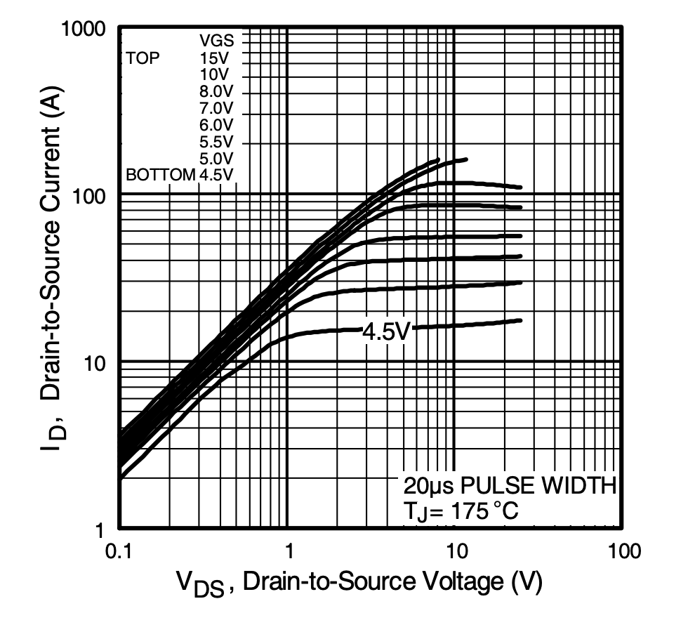
- At VGS = 4.5 V, the IRFZ44N can conduct 10 A or more, but not at minimal losses.
- At VGS > = 10 V, it reaches full conduction with an RDS(on) of ~17 mΩ.
So, when using it with Arduino:
- It can act as a switch, but not an efficient linear amplifier or PWM speed controller.
- Always use a heatsink if drawing more than 1 A, since partial conduction increases dissipation.
Comparisons with Similar MOSFETs
The IRFZ44N often gets compared with a few other well-known MOSFETs in its class, and understanding these differences helps you pick the right one for your design.
IRF540N:
This 100 V, 33 A HEXFET from the same family offers a higher voltage rating but at the cost of efficiency. Its on-resistance (RDS(on)) is around 52 mΩ at 10 V gate drive ,roughly three times that of the IRFZ44N’s 17.5 mΩ.
If your circuit runs above 55 V, the IRF540N is a safer choice. Otherwise, the IRFZ44N provides lower conduction losses and better efficiency.
IRLZ44N:
Think of this as the logic-level version of the IRFZ44N. It’s rated 60 V/50 A with (RDS(on))≈ 28 mΩ at just a 5 V gate drive. That makes it ideal for microcontroller-based circuits or low-voltage systems where you don’t have a dedicated gate driver.
The IRFZ44N, by contrast, needs about 10 V on the gate to switch fully but rewards you with even lower resistance and heat generation when driven properly.
IRFZ34N:
A smaller 55 V, 30 A MOSFET with (RDS(on))≈ 20 mΩ, it’s similar in design but handles less current and is less common in high-power builds.
The IRFZ44N stands out for its low on-resistance and strong current capacity within the 55 V range.
It’s not the best fit for direct logic-level control, but in systems with a 12 V or dedicated driver supply, it delivers excellent switching efficiency and reliability making it a favorite for motor drivers, DC converters, and power control circuits.
Applications of the IRFZ44N MOSFET
The IRFZ44N is one of the most widely used N-channel MOSFETs due to its balance of high current handling, low on-resistance, and fast switching performance. These qualities make it ideal for a broad range of power electronics applications from everyday DIY circuits to industrial-grade controllers.
1. Motor Control and Robotics
The IRFZ44N is a popular choice for DC motor drivers, PWM speed controllers, and robotic actuators.
Its 49 A continuous drain current capability allows it to switch large motor loads efficiently.
It’s commonly used in H-bridge circuits and half-bridge drivers, where precise gate control enables smooth and reversible motor operation.
2. Power Supplies and Converters
In buck, boost, and flyback converters, the IRFZ44N serves as the main switching element. Its low RDS(on) (≈17 mΩ) and high switching speed minimize conduction and switching losses, improving overall efficiency.
You’ll often find it in DC-DC converters, inverters, and battery charging circuits, where reliability and thermal performance are critical.
3. Audio Amplifiers

Although it’s primarily a power switch, the IRFZ44N also finds use in Class-D audio amplifiers and MOSFET output stages.
Its fast transition speed and low internal capacitance allow it to reproduce signals cleanly at high power levels without significant distortion.
4. LED and Lighting Drivers

In high-power LED systems, the IRFZ44N is used to switch current through LED arrays in response to PWM dimming signals. Its robust current handling ensures consistent brightness control while maintaining efficiency and thermal stability.
5. Battery Management and Solar Systems
The IRFZ44N is widely integrated into battery protection, charging controllers, and solar charge regulators. It can efficiently handle high currents in low-voltage DC systems such as 12 V or 24 V solar setups making it a dependable choice for renewable-energy projects.
6. Automotive Electronics
Because it operates comfortably in the 12 V range, the IRFZ44N is often found in automotive circuits such as headlight controllers, power window systems, electronic throttle controls, and inverter modules. Its rugged construction and avalanche energy rating make it reliable even in harsh environments.
7. General Switching Applications
Any circuit that requires high-current, low-voltage switching can benefit from the IRFZ44N from relay replacements and solenoid drivers to heater controllers and power distribution units.
Final Thoughts
The IRFZ44N has earned its reputation as a dependable, high-performance MOSFET that continues to hold its ground even in today’s fast-evolving electronics world.
Whether you’re building a DC motor driver, a solar power controller, or a high-current switching circuit, the IRFZ44N delivers the muscle and reliability you need.
Its low on-resistance, high current capacity, and fast switching speed translate directly into cooler operation and higher efficiency provided it’s driven and cooled properly.
What really sets the IRFZ44N apart is its versatility. It’s equally at home on a breadboard powered by a 12 V supply as it is inside an industrial inverter or a custom audio amplifier.
With a proper gate driver, solid thermal design, and attention to layout, this MOSFET can easily become the backbone of your power electronics projects.
In short, the IRFZ44N isn’t just another transistor , it’s a proven workhorse that bridges the gap between performance and practicality.
If your design calls for a rugged, efficient switch that can handle serious current without breaking the bank, the IRFZ44N remains one of the best choices you can make.
If you are looking to source this transistor, Flywing Tech offers the complete IRFZ44N MOSFET family, including through-hole and surface-mount options for every design need from prototyping to production-scale builds.
You can explore all available variants, compare specifications, and order in bulk directly from the product catalog.

Frequently Asked Questions (FAQs)
1. What is the IRFZ44N MOSFET used for?
The IRFZ44N is a power N-channel MOSFET commonly used for switching and amplification in circuits that handle moderate to high current. It’s popular in motor controllers, DC-DC converters, solar charge controllers, and automotive systems.
2. Is the IRFZ44N a logic-level MOSFET?
No. The IRFZ44N is not a true logic-level MOSFET , it requires around 10–12 V at the gate to fully turn on. For 5 V logic-level control, use IRLZ44N, which is designed for low-voltage gate drive.
3. What is the maximum voltage and current the IRFZ44N can handle?
It can handle up to 55 V Drain–Source voltage and 49 A continuous current when properly cooled. Short pulses can go as high as 160 A, depending on thermal limits.
4. How do I drive the IRFZ44N from a microcontroller?
Microcontrollers typically output 3.3–5 V, which isn’t enough to fully switch the IRFZ44N. Use a MOSFET driver IC such as TC4420 or IR2110 to boost the gate voltage to 10–12 V. This ensures efficient switching and prevents excessive heat buildup.
5. Can I use the IRFZ44N without a heatsink?
Only for low-current or short-duration switching. The device can dissipate up to 94 W with proper heatsinking, but without it, junction temperatures rise quickly. Always use a heatsink if the MOSFET carries more than a few amps continuously.
6. What is the difference between IRFZ44N and IRLZ44N?
The main difference is gate threshold voltage.
- IRFZ44N: Needs ~10 V to fully turn on (standard MOSFET).
- IRLZ44N: Fully turns on at ~4–5 V (logic-level MOSFET).
If you’re using 5 V logic signals, go with IRLZ44N. For higher-voltage driver circuits, IRFZ44N is more efficient.
7. Why is my IRFZ44N heating up?
It’s usually due to insufficient gate voltage, high switching frequency, or poor heat dissipation. Ensure the gate is driven at 10–12 V, use a driver IC, and mount the transistor on a heatsink. Also check that your load current doesn’t exceed safe limits.
8. How can I protect the IRFZ44N from voltage spikes?
Use flyback diodes, RC snubber networks, or TVS diodes across inductive loads. These components absorb or redirect energy spikes that could exceed the MOSFET’s voltage rating and cause avalanche failure.
9. Can the IRFZ44N be used in high-frequency circuits?
Yes, but within limits. It has fast switching times , so it performs well up to a few hundred kilohertz. For MHz-range switching, consider MOSFETs with lower gate charge and capacitance.
10. How do I test if my IRFZ44N is working?
Use a multimeter in diode mode:
- Test between Drain and Source , the body diode should show about 0.7–1.0 V forward drop.
- Apply a small voltage (5–10 V) between Gate and Source — Drain–Source resistance should drop significantly, showing that the MOSFET is turning on.
11. What causes IRFZ44N failure in circuits?
Common causes include:
- Gate overvoltage (> ±20 V)
- Excessive current or heat without a heatsink
- Inductive spikes without flyback protection
- Parasitic oscillations from long gate traces
Using proper gate resistors, diodes, and snubbers prevents most failures.
12. Can I parallel multiple IRFZ44Ns for higher current?
Yes, but match them carefully. Use small source resistors (0.01–0.1 Ω) for current balancing and ensure equal gate drive. Without balancing, one MOSFET may hog current and fail prematurely.
13. What are typical real-world applications of the IRFZ44N?
- PWM motor drivers and H-bridges
- DC-DC converters and voltage regulators
- Solar charge controllers and battery systems
- LED dimmers and lighting controls
- Audio power amplifiers (Class D)
- Automotive switching circuits (12–24 V systems)
14. Is IRFZ44N suitable for AC applications?
Not directly. It’s designed for DC or low-frequency switching. For AC loads, use it in an inverter or rectifier stage where the AC signal is converted to DC-controlled switching.
15. What makes the IRFZ44N so popular among hobbyists?
It’s affordable, widely available, and extremely tolerant of real-world conditions. Its 55 V / 49 A capability covers most DIY and educational projects, from motor controls to Arduino-based power circuits, making it a trusted choice for learners and professionals alike.