Introduction
Capacitors hold an essential role in any power supply design. Although they are smaller and cheaper than semiconductors and transformers, inappropriate choice of capacitor leads to overheating, ripple voltage, electromagnetic interference (EMI), reduced efficiency, and circuit failure.
Capacitors are widely used in DC-DC converters, motor controllers, linear regulators, and industrial power supplies. Therefore, to ensure long-term reliability and stable performance in such applications, it is critical to understand how to select the right capacitor for a specific application.
This article explains an engineering methodology for the Capacitor Selection of power supply design. This guide mainly focuses on voltage ratings, capacitance value, ripple current, temperature, lifetime, type of dielectric material, and proper placement. In addition, case studies based on real-world applications are also covered to help designers make better decisions.
Why Capacitor Selection is Important in Power Supplies?
When designing a power supply, designers mainly focus on controllers, MOSFETs and magnetics (check our MOSFET selection guide). However, capacitor selection is equally important because it directly impacts several system parameters.
Depending on the capacitor placement, choice of capacitor is directly related to output ripple voltage, input voltage stability, load transient response, thermal reliability, EMI performance, and lifetime of the device.
Therefore, a poor capacitor selection can lead to unstable regulation, excessive ripple, noise, and lower lifetime.
Role of Different Capacitors in Power Supply Design
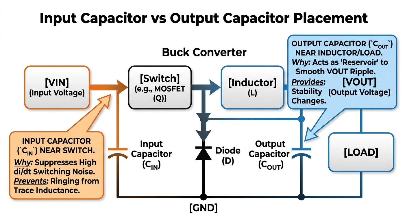
Before selecting a capacitor, it is essential to identify where it is used in the system. Based on the circuit placement, capacitors can serve different roles. Such as input capacitor is used to filter out transients coming from input supply, while decoupling capacitors are placed close to the IC pins to avoid high-frequency noise (see Fig-1).
The table below summarizes type of capacitors and their specific role in the power supply design.
| Type of Capacitor | Role |
| Input capacitor | It is placed near the input source and reduces input voltage dips |
| Output capacitor | Located at load/output side and helps in reducing load transients |
| Decoupling capacitor | This is used as close as possible to IC pins and suppress high-frequency noise |
| Bulk capacitors | Although there is no fix position, this provides stored energy for sudden load demand or startup. |
Important Key Parameters for Capacitor Selection
Capacitance Value
One of the most important and basic parameters is capacitance. This refers to amount of energy a capacitor can store and typically measured in µF, nF, pF. Higher capacitance value result in lower ripple voltage and better transient support (for example, see Samsung 47 µF MLCC).
Output ripple in many switching power supplies can be approximated by the equation given below:
\[\Delta V=\frac{I}{fC}\]
Where:
ΔV= Ripple voltage
I= Ripple current components
f= Switching frequency
C= Capacitance
According to given equation, ripple decreases as the capacitance value increases. However, excessive capacitance leads to higher startup inrush current, size and cost (Infineon’s MLCC DC bias guide).
Voltage Rating
It is the maximum voltage a capacitor can sustain. Rule of thumb is to always apply safety margin such that capacitors should be rated at least 1.25 times the operating voltage. Mathematically:
\[V_{rated}\ge1.25\times V_{operating}\]
For example: For a 12V rail, using a 16V capacitor is safer than using exact 12V capacitor.
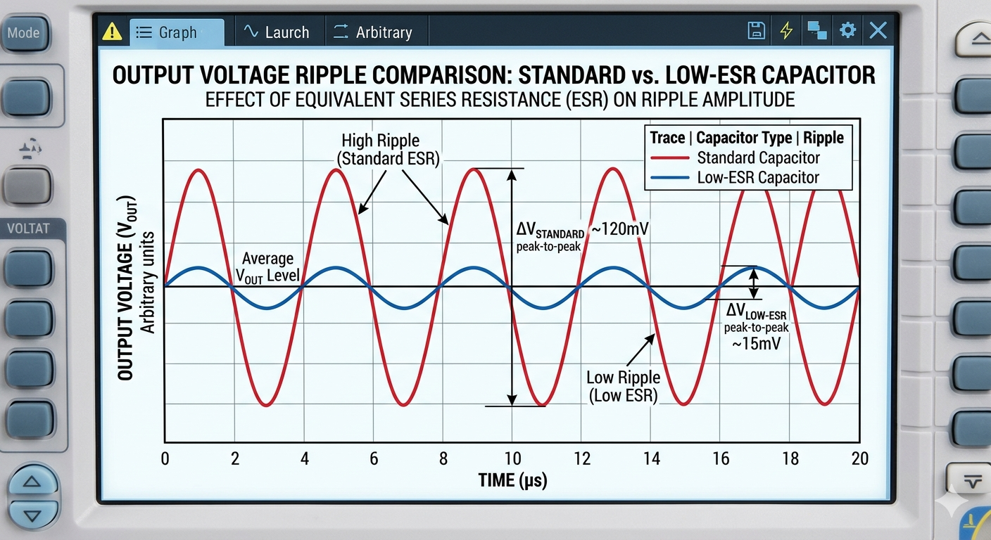
Equivalent Series Resistance (ESR)
ESR represents the internal resistance of a capacitor. The materials like electrolytes, foils, leads create a small amount of resistance that acts in series with capacitance.
Higher ESR results in higher ripple voltage, heat generation (P=I2R), reduced efficiency, and poor transient response. The ripple caused by ESR is estimated as:
\[V_{ESR}=I_{ripple}\times ESR\]
Therefore, low-ESR capacitors are preferred in power supply applications (For additional discussion check this guide).
Ripple Current
The ripple current for a capacitor is the maximum RMS alternating current it can handle without overheating or failure. It arises from AC voltage fluctuations on a DC line, such as in switching power supplies or input/output filters.
Datasheets generally provide maximum ripple current rating for every capacitor. If ripple current exceeds that value, internal heating increases leading to device failure (check ripple fundamentals here).
Temperature Rating
Like MOSFETs or other electronic components, temperature rating strongly affects capacitor lifetime. Common temperature ratings for capacitors are from 85°C-125°C (See why MOSFET fails in power circuits).
Choice of capacitor depends on environment they are going to be used. In hot environments such as motor drives, LED power supplies, and automotive electronics, higher temperature capacitors are used.
Capacitor Lifetime
Although not always explicitly mentioned in datasheet, Capacitor lifetime is critical parameter especially in products expected to operate continuously. Applications such as telecom systems, industrial power supplies, solar inverters, EV and auxiliary systems place strong emphasis on reliability.
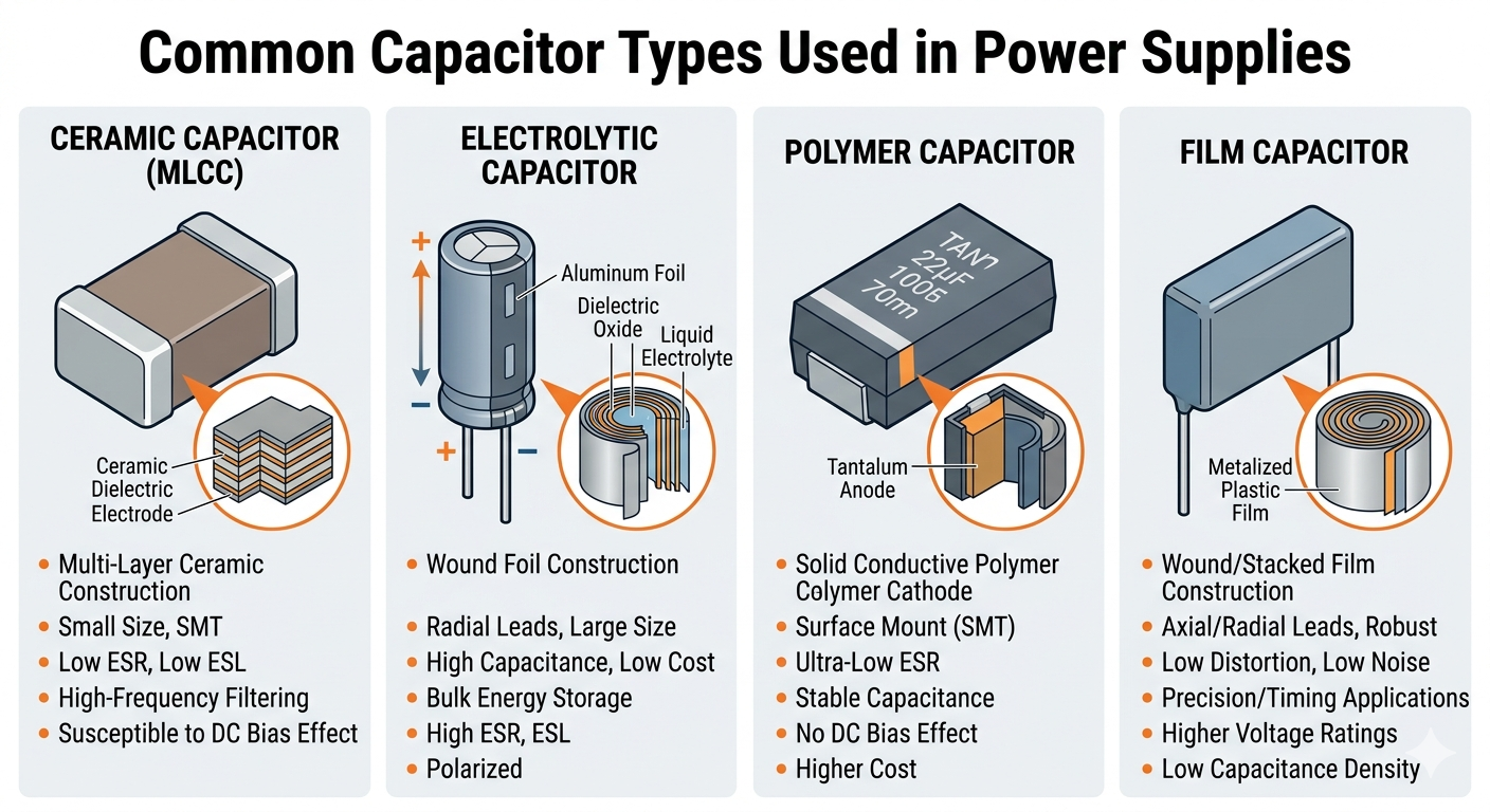
Type of Capacitors and Where to Use Them
| Capacitor type | Where to use | Advantages | Limitations |
| Ceramic capacitor | -High-frequency decoupling -Output filters -Compact designs | -Very low ESR -Small size -High reliability | -Capacitance drops with DC bias -Creates audible noise in some converters |
| Electrolytic capacitors | –Energy storage -Input filters -Low-cost power supplies | -High capacitance -Economical | -Higher ESR than ceramic capacitors -Lower lifetime |
| Film capacitors | -High voltage applications -Snubber circuits -AC filtering | -Excellent stability -Longer lifetime -Lower loss | -High cost -Lower capacitance |
| Polymer capacitors | -Low ESR applications -Fast transient loads | -Low ESR -Better ripple handling | -Higher cost compared to electrolytic capacitors -Lower voltage ratings in some cases |
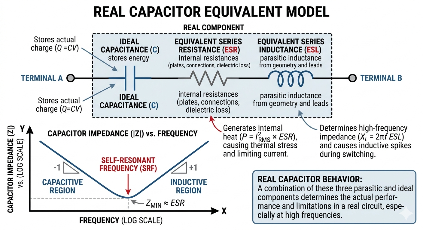
Capacitor Selection: Parasitic Issues (ESR and ESL)
Parasitic parameters, ESR and Equivalent Series Inductance (ESL) are as important as datasheet parameters. In real applications, the impedance (Z) of capacitor is defined by parasitic parameters:
ESR= The resistance of dielectric material, plates, and internal connections.
ESL= The inductance formed by leads and physical geometry of the component.
The impedance of capacitor at given frequency is given by:
\[Z=\sqrt{ESR^2+\left(X_C-X_L\right)^2}\]
Where:
\[X_C=\frac{1}{2\pi f C}\]
\[X_L=2\pi f \, L\]
WHY ESL and ESR Matter
These parasitic parameters significantly affect capacitor performance particularly in high-frequency switching applications (see Fig-3).
As shown in equation above, during the lower frequency operation, capacitive reactance (XC) dominates the capacitor behaviour. While as frequency increases, the capacitor approaches its self-Resonant Frequency (SRF). In this case, XC and XL cancel each other and impedance of capacitor is determined by its ESR.
Beyond SRF, the capacitor starts exhibiting inductive behaviour due to ESL. This becomes very critical in power converters where transient currents (di/dt) are present. If capacitor with high ESL is used, transient currents generate significant voltage spikes across the parasitic inductance resulting in degradation in capacitor performance.
Therefore, ESR and ESL are considered when selecting capacitors for power supply design.
Important Parameters in Capacitor Datasheet
- Capacitance
- Voltage ratings
- ESR/impedance curve
- Ripple current rating
- Temperature range
- Mounting style
- Dimensions
Output Filter Design for Buck Converter: A Case Study
To identify how capacitor selection affects real power supply performance, a buck converter design example is explained in this section.
Design Scenario
A designer needs to develop a synchronous buck converter with following requirements:
| Voltages levels (Vin and Vout) | 12V-3.3V |
| Load Current (Iload) | 10A |
| Type of Load | FPGA |
| Converter switching frequency | 500kHz |
| Allowable ripple (ΔV) | 30mV peak-to-peak |
In this type of application, choice of output capacitor is critical for voltage stability and noise performance.
Design Approach
To select an appropriate capacitor for a buck converter, several parameters need to be understood.
Step-1: Calculating required capacitance
Using the ripple approximation formula, (Assuming ΔIL=2A)
\[\Delta V=\frac{\Delta I_L}{8f_sC}\]
\[C=\frac{\Delta I_L}{8f_s\Delta V}\]
Substituting values:
\[C=\frac{2}{8(500\times10^3)(30\times10^{-3})}\]
\[C\approx16.7\mu F\]
This gives a theoretical value, however in real designs a capacitor with higher capacitance is usually selected to account for load transients.
Step-2: Voltage rating
The output voltage is 3.3V, however, designers always apply safety margin.
\[V_{rated}\ge1.25\times V_{operating}\]
Hence, capacitor should sustain minimum voltage of
\[V_{rated}\ge4.125V\]
Step-3: Understand ESR requirements
It is highly recommended to make sure that ripple due to ESR remain below specification.
\[\Delta V_{ESR}=\Delta I_L\times ESR\]
For the ripple below 20mV (keeping the safety margin), allowable ESR becomes
\[ESR\le\frac{20mV}{2A}=10m\Omega\]
(See Fig-4 to understand effects of ESR on ripple)
Step-4: Ripple current capability
Assuming ripple current stress is Iripple=2A, the selected capacitor should have higher ripple current rating.
Step-5: Consider ESL due to high frequency operation
Since the converter switching frequency is higher (500kHz), high transient suppression is also important.
This suggests that low ESL capacitor can be a suitable choice for this application.
Capacitor selection
| Parameter | Calculated Requirement | Potential Choice |
| Capacitance | 16.7µF minimum | 22–47 µF low-ESR capacitor |
| Voltage Rating | 4.125V | 6.3 V rated capacitor |
| ESR | 10mΩ | Low-ESR capacitor meeting requirement |
| Ripple Current | 3A | Capacitor rated above 3 A |
| High-Frequency Filtering | Low ESL preferred | Optional ceramic bypass capacitor |
A practical solution for this design should be a 22-47uF capacitor with low ESR. An optional ceramic capacitor can be used to decouple high-frequency noise.
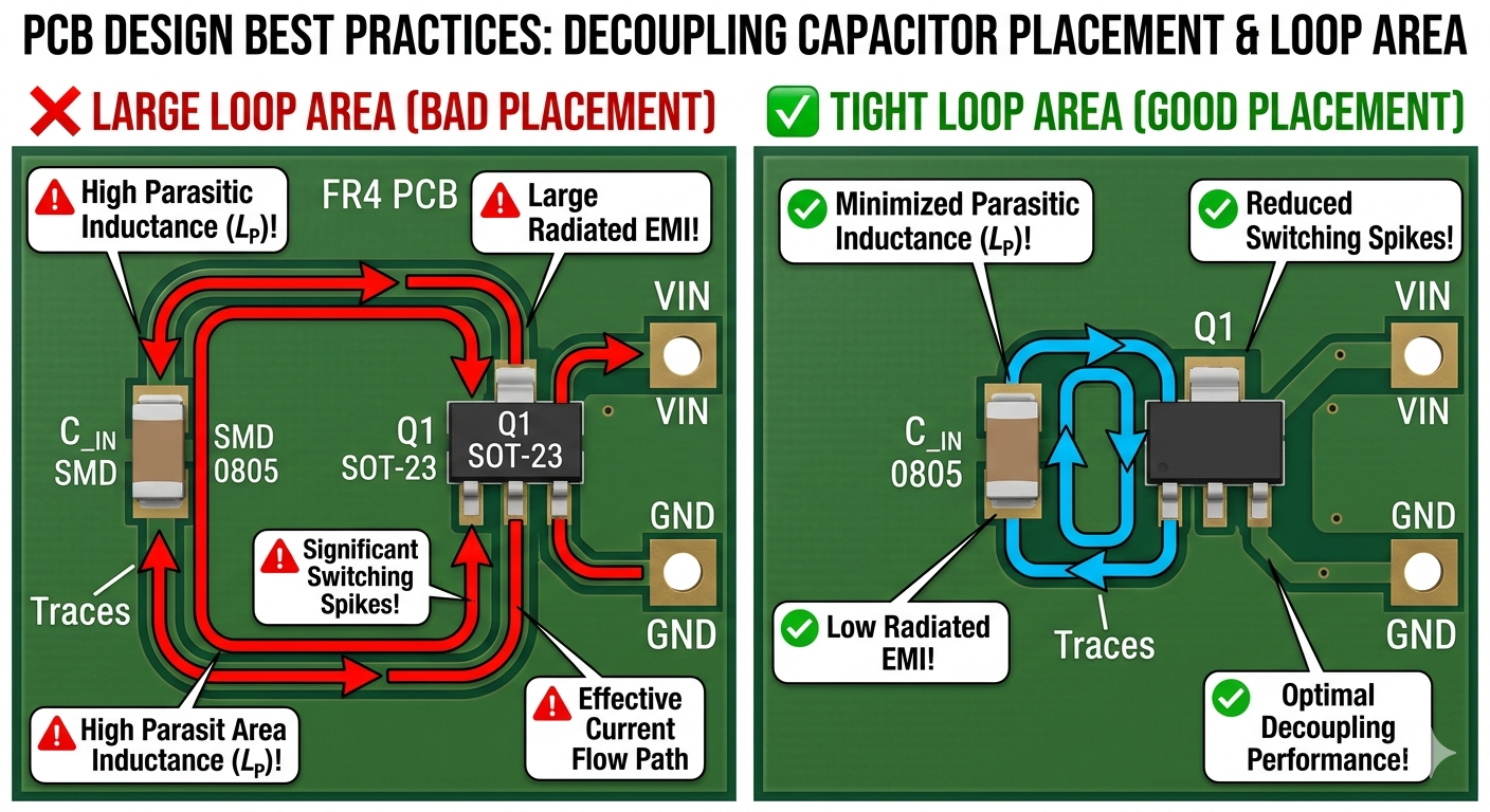
PCB Layout and Capacitor Placement
Proper PCB placement is equally important as selecting the right capacitor. The parasitics introduced by poor PCB layout can degrade capacitor performance (See Fig-5). The following practices help minimize these effects and improve power supply performance.
- Capacitor placement near switching nodes: Capacitors are placed as near as possible to switching devices to reduce parasitic inductance.
- Shorten loop area: Keep high di/dt current loop between input capacitor, switching device, and ground as small as possible to avoid voltage spikes, ringing, and EMI.
- Use vias carefully: Vias can add unwanted inductances. If vias are necessary, use multiple in parallel to lower net inductance.
Modern Trends in Power Supply Capacitors
Technologies continue to improve over time. Recent trends in capacitor technology include:
- Conductive polymer capacitors with very low ESR
- Hybrid capacitors combining advantages of multiple technologies
- High temperature capacitors
- High-capacitance MLCC capacitors in smaller packages
Capacitor Selection Checklist
Before making a final choice, multiple questions should be answered.
Q1: What is purpose of this capacitor?
Q2: What is operating voltage of system?
Q3: What ripple voltage does the system allow?
Q4: What maximum temperature must it withstand?
Q5: How big/small ESR is?
Conclusions
An appropriate choice of capacitor for power supply design requires more than selecting a capacitance value. Designers also need to consider voltage derating, ripple current, ESR, temperature, lifetime, PCB placement, and different operating conditions.
Whether designing a simple DC supply or advanced converters, capacitor selection has a direct impact on final system performance. Because a properly selected capacitor results in improved efficiency, lower ripple, enhanced stability and extended lifetime of product.
Frequently Asked Questions (FAQs)
Large value capacitors such as electrolytic capacitors often have higher ESL, which means they are not suitable for functioning at higher frequency. In contrast, capacitors with smaller capacitance (ceramic capacitors) have lower ESL but cannot store bulk energy.
Designers use multiple capacitors (with different capacitances) in parallel to create composite impedance curve that remains extremely low across a higher frequency range, suppressing high frequency noise. This phenomenon is often called broadband decoupling.
These codes refer to temperature range and maximum capacitance drift. X7R capacitors can operate between -55°C to 125°C with a capacitance drift of 15%. While X5R goes upto 85°C with the same capacitance drift.
Y5V operates under the range of -30°C to 85°C, however they can lose 22% to -82% of their capacitance across this range. From power supply perspective, X7R and X5R are strongly recommended.
Short answer is no. Replacing electrolytic blindly with a ceramic capacitor can lead to system instability. Switching regulators and linear regulators (LDOs) are carefully compensated for a specific range of ESR. Electrolytic capacitors inherently provide a “zero” in the control loop due to their high ESR, which aids in stability. Replacing it with an ultra-low ESR ceramic capacitor removes this zero, often causing the power supply to oscillate strongly.
Common reasons include overheating, excessive ripple current, overvoltage, poor quality parts, and aging.
COMMENTS