If you’ve ever worked with an Arduino Leonardo, Micro, or Pro Micro, you’ve already used the ATmega32U4. It is a small but capable microcontroller that gives those boards their native USB power.
Unlike most 8-bit chips, it doesn’t need an extra USB-to-serial converter. It can connect directly to your computer and act like a keyboard, mouse, or serial device, which makes it ideal for modern USB-based projects.
That built-in USB capability is what makes the ATmega32U4 so popular among makers, hobbyists, and embedded engineers alike.
In this guide, we’ll explore everything you need to know about the ATmega32U4, from its features and pinouts to how it’s programmed and used in real projects.
Whether you’re experimenting with your first USB gadget or integrating it into a professional design, you’ll see why this microcontroller has become a reliable favorite across the electronics community.
What is the ATmega32U4?
The ATmega32U4 is an 8-bit microcontroller developed by Atmel (now part of Microchip Technology), belonging to the popular AVR family of chips.

It’s best known for powering well-loved boards like the Arduino Leonardo, Arduino Micro, and SparkFun Pro Micro, all of which stand out because they can connect directly to a computer through USB.
At its core, the ATmega32U4 is designed for projects that need direct USB communication, moderate processing power, and low energy consumption in a compact package.
It brings together a mix of simplicity, versatility, and integrated peripherals that make it a go-to choice for both prototyping and product development.
ATmega32U4 Technical Specifications & Architecture
Before we get into pinouts and real-world use, let’s examine what makes the ATmega32U4 such a versatile microcontroller.
Its architecture blends the simplicity of an 8-bit AVR core with advanced peripherals like USB, multiple timers, and flexible power control.
Now lets dive deeper into technical specifications and architecture.

ATmega32U4 Core Architecture & Performance
At the heart of the ATmega32U4 is an 8-bit AVR enhanced RISC core, optimized for speed and low power.
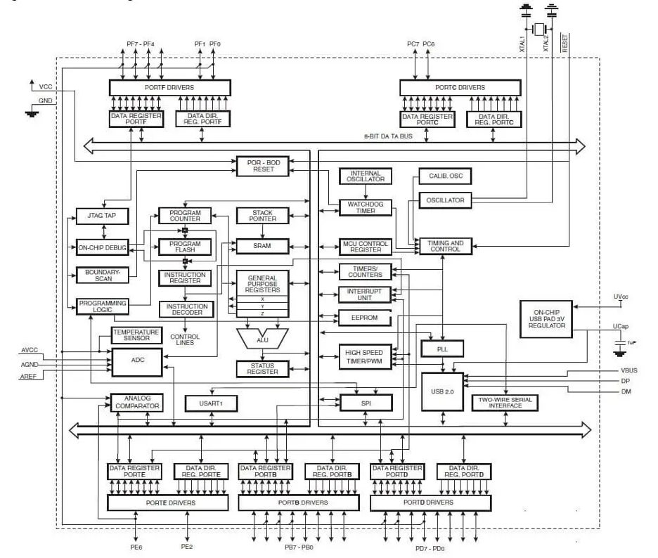
It features 32 general-purpose registers tightly coupled to the Arithmetic Logic Unit (ALU). Moreover, a built-in hardware multiplier accelerates math operations, making the device suitable for timing, control, and communication tasks without overloading the CPU.
For complete block-level details, see the official ATmega32U4 datasheet from Microchip.
Memory Organization
The ATmega32U4 provides a well-balanced memory layout for compact yet capable applications:
- Flash memory: 32 KB (about 28 KB available for user code when using the default USB bootloader).
- SRAM: 2.5 KB for variables, stack, and buffers.
- EEPROM: 1 KB for non-volatile data such as calibration or configuration settings.
Both the flash and EEPROM support in-system programming and read-while-write operation, meaning code can be executed from one flash section while another is being updated.
Operating Voltage & Frequency
The ATmega32U4 operates from 2.7 V to 5.5 V, allowing it to work equally well in 3.3 V battery systems and 5 V embedded environments.
At lower voltages, it’s limited to 8 MHz operation, while at 4.5–5.5 V it can safely run at the full 16 MHz.
The chip is rated for an industrial temperature range of –40 °C to +85 °C, making it suitable for portable, outdoor, or embedded use cases.
Instruction Set & Efficiency
Like other AVRs, it features a rich instruction set of 135 operations, most of which execute in one cycle.
The Harvard architecture (separate program and data buses) allows parallel instruction fetch and data access, improving throughput.
This, combined with the single-cycle instruction execution, makes the ATmega32U4 efficient for time-critical routines, bit manipulation, and interrupt-driven tasks.
Integrated Peripherals
Despite its small footprint, the ATmega32U4 integrates a range of useful on-chip peripherals:
- USB 2.0 Controller: The key differentiator. It supports full-speed (12 Mb/s) and low-speed (1.5 Mb/s) device operation with a dedicated 832-byte DPRAM buffer and up to six configurable endpoints. It can generate interrupts on transfer completion, making it ideal for HID and serial device emulation.
- Timers & Counters: Includes one 8-bit timer, two 16-bit timers, and one high-speed 10-bit timer with a PLL that can tick up to 64 MHz — perfect for precision PWM, frequency measurement, or signal generation.
- PWM Outputs: Up to 11 PWM channels for motor control, LED dimming, or analog signal generation.
- ADC (Analog-to-Digital Converter): A 12-channel, 10-bit ADC that can measure analog voltages (typically 0–5 V) and supports differential readings with programmable gain for sensor interfacing.
- Communication Interfaces:
- USART (UART) for serial communication with optional flow control.
- I²C (TWI) for sensor or peripheral interconnects.
- SPI for fast synchronous data transfer.
This combination allows the MCU to handle USB communication with a PC while simultaneously talking to sensors or other microcontrollers through serial, I²C, or SPI.
Complete ATmega32U4 Pinout & Pin Functions
The ATmega32U4 comes in a 44-pin TQFP or QFN package, offering a high level of functionality in a compact footprint.
Out of its 44 pins, several are reserved for power, ground, and special functions, while 26 pins can serve as general-purpose I/O (GPIO).
Let’s look at how these pins are organized and what each category does.
Power Pins
Stable power delivery is crucial for microcontroller performance. The ATmega32U4 includes several dedicated pins for clean and reliable operation:
- VCC (pins 14 & 34): Digital power supply pins.
- AVCC (pins 24 & 44): Analog supply pins. Connect these to VCC through a low-pass filter (typically a ferrite bead and capacitor) when using the ADC to minimize noise.
- GND (pins 15, 23, 35, 43): Four ground pins to ensure solid grounding and low impedance.
- AREF (pin 42): Analog reference voltage input for the ADC. Use this for an external reference or to decouple the internal reference for more stable analog readings.
Add 0.1 µF decoupling capacitors near each VCC and AVCC pin to maintain stable voltage and reduce noise.
USB Interface Pins
The native USB transceiver is what makes the ATmega32U4 stand out. It has dedicated USB lines for full-speed communication with a host system.
- D– (pin 3) and D+ (pin 4): Differential USB data lines. Add 22 Ω resistors in series for signal quality and include ESD protection near the connector.
- UVCC (pin 2): Provides 5 V power from USB to the internal 3.3 V regulator.
- UCAP (pin 6): Connect a 1 µF capacitor to stabilize the internal regulator.
- UGND (pin 5): USB ground reference.
- VBUS (pin 7): Detects the presence of 5 V from the USB host. Often connected through a resistor divider if used as a sensing input.
For reliable operation, all USB-related pins must be connected correctly and decoupled as recommended in the datasheet.
Crystal & Clock Pins
The ATmega32U4 can run on its internal 8 MHz RC oscillator, but most designs use an external crystal for precise timing, especially when USB is active.
- XTAL1 (pin 17) and XTAL2 (pin 16): Input and output pins for an 8 MHz or 16 MHz crystal oscillator.
If no external crystal is used, these can be left unconnected. However, for full-speed USB operation, an accurate 16 MHz clock source is recommended.
Reset & Bootloader Pins
The chip provides dedicated pins for manual reset and bootloader activation.
- RESET (pin 13): Active-low reset input. Usually connected to a push button and a pull-up resistor.
- HWB / PE2 (pin 33): Hardware Boot Enable pin. Holding this pin low during reset activates the DFU bootloader for USB programming. If not used for bootloader purposes, it can function as a regular I/O pin.
Digital I/O Pins
The ATmega32U4 includes 26 programmable digital I/O lines, distributed across Ports B, C, D, E, and F. Each pin supports multiple roles such as GPIO, PWM, communication, or analog input.
1. Port B (PB0–PB7)
- Multipurpose lines used for SPI and PWM.
- PB0: Often connected to the on-board RX LED.
- PB1: SPI clock (SCK).
- PB2: MOSI. PB3: MISO.
- PB4–PB6: Dual-function pins that can act as ADC inputs (ADC11–ADC13) and PWM outputs.
- PB7: Timer output (OC0A or OC1C).
2. Port C (PC6–PC7)
- Two digital I/O pins that also serve as timer outputs.
- PC7 can output the system clock or serve as capture input.
- On some boards, PC6 or PC7 is used for the “L” indicator LED.
3. Port D (PD0–PD7)
- A versatile port that handles several interfaces.
- PD0 (SCL) and PD1 (SDA): I²C (TWI) lines.
- PD2 (RXD1) and PD3 (TXD1): UART Serial1 interface.
- PD4, PD6, PD7: Can be used as analog inputs (ADC8–ADC10) or timer outputs.
- PD5: Connected to the TX LED on many Arduino Leonardo or Micro boards.
4. Port E (PE2, PE6)
- PE2: The Hardware Boot (HWB) pin, also usable as GPIO.
- PE6: Acts as an external interrupt input (INT6) or comparator input (AIN0–).
5. Port F (PF0–PF7)
- Main analog port for ADC0–ADC7.
- On Arduino boards, PF7–PF4 map to A0–A5, and PF1–PF0 may serve as A6–A7 if supported.
- PF4–PF7 also serve as JTAG interface pins (TCK, TMS, TDO, TDI). When JTAG is enabled, these pins cannot be used for analog or GPIO functions until disabled.
Many ATmega32U4-based boards reserve certain pins for built-in features.
- PB0: RX LED indicator.
- PD5: TX LED indicator.
These pins can be reassigned as GPIO if the LEDs are not required, though the logic is inverted (LOW turns the LED on).
Always verify the pin mapping if you’re using the Arduino IDE, since some pins may differ depending on the board layout.
How to Program ATmega32U4
One of the main reasons the ATmega32U4 is so popular is its flexibility in programming. You can upload code directly through USB, use the ICSP (In-Circuit Serial Programming) interface, or rely on JTAG for advanced debugging.
Each method has its own workflow depending on whether you’re building a prototype, manufacturing a board, or recovering a bricked device.
Let’s go through each method step by step.
USB Programming with the Built-in Bootloader
Most ATmega32U4 chips (like those on the Arduino Leonardo or Micro) come with a factory-installed USB bootloader.
This allows direct programming through a USB cable without needing extra hardware.
Steps to Program via USB (Arduino IDE Method)

- Connect the board: Plug your ATmega32U4 board into your computer using a standard USB cable.
- Install drivers (if required):
- On Windows, the board will appear as “Arduino Leonardo (COMx).”
- On macOS and Linux, no extra drivers are usually needed.
- Open Arduino IDE:
- Go to Tools → Board → Arduino Leonardo (or Micro, depending on your board).
- Select the correct COM port under Tools → Port.
- Write or open your code:
- Enter your sketch or open an existing program.
- Upload the program:
- Click Upload (the right arrow icon).
- The IDE resets the board automatically, puts it into bootloader mode, and sends the c ompiled code.
- The RX/TX LEDs blink during upload.
- Verify completion:
Once uploaded, the board restarts and runs your new code automatically.
If the upload fails or your board isn’t detected:
- Double-press the Reset button within 1 second to enter bootloader mode manually.
- The board should reappear as a different COM port (bootloader mode).
- Try uploading again immediately.
- If it still doesn’t respond, you may need to re-burn the bootloader using ICSP (see below).
You can also force the chip into bootloader mode by holding the HWB pin low during reset, though this is rarely needed on Arduino-compatible boards.
If your project requires leveraging bootloader space, Flash size, or specific package tradeoffs, check out Flywing’s full ATmega32U4 catalog e.g. ATmega32U4RC-AU or ATmega32U4RC-MU for small-footprint versions or variants with enhanced thermal margins.
ICSP Programming (In-Circuit Serial Programming)
ICSP is the standard method used to program AVR chips using the SPI interface.
It’s ideal for blank chips, custom boards, or recovering a microcontroller that lost its bootloader.
The ATmega32U4 has a 6-pin ISP interface that uses the following signals:
| Signal | Pin on ATmega32U4 | Typical Function |
| MOSI | PB2 | Master Out Slave In |
| MISO | PB3 | Master In Slave Out |
| SCK | PB1 | SPI Clock |
| RESET | Pin 13 | Resets the chip for programming |
| VCC | Pin 14/34 | Power Supply |
| GND | Pin 15/23/35/43 | Ground |
Steps to Program via ICSP (Using Arduino as ISP)

- Prepare your programmer: Upload the ArduinoISP sketch to an Arduino Uno (found in File → Examples → 11.ArduinoISP).
- Make the connections: Connect your Uno to the ATmega32U4 as follows:
- D11 → PB2 (MOSI)
- D12 → PB3 (MISO)
- D13 → PB1 (SCK)
- D10 → RESET
- 5V / 3.3V → VCC (match your target voltage)
- GND → GND
- Configure Arduino IDE:
- Go to Tools → Board → Arduino Leonardo (if you plan to burn the Leonardo bootloader).
- Select Programmer → Arduino as ISP.
- Burn the bootloader:
- Click Tools → Burn Bootloader.
- The IDE will write the bootloader to flash and set proper fuse bits.
- Switch to USB for regular uploads:
- After burning, unplug the ICSP wiring and connect your board via USB. You can now upload sketches directly through the built-in bootloader.
If you have a USBasp, Atmel-ICE, or AVRISP mkII, you can program the ATmega32U4 using AVRDUDE or Microchip Studio.
- Connect the programmer to the 6-pin ISP header on your board.
- Select the correct target device (ATmega32U4).
- Load your hex file or bootloader image.
- Start the write operation.
- Verify flash integrity after completion.
ICSP overwrites the existing bootloader. To return to USB uploads later, re-burn the bootloader first.
JTAG Programming and Debugging
The JTAG interface on the ATmega32U4 is designed for professional use. It not only allows programming but also provides in-circuit debugging, letting you pause and inspect your program while it runs.
Steps to Program via JTAG

- Connect your JTAG programmer: Use a device such as Atmel-ICE, JTAGICE mkII, or JTAGICE3. Connect it to the 6-pin or 10-pin JTAG header on your board.
- Open Microchip Studio:
- Select Device → ATmega32U4.
- Choose Interface → JTAG.
- Pick your connected tool.
- Write firmware: Load your compiled .hex file and click Program Device.
- Debug firmware (optional): You can now use breakpoints, watch variables, and step through code in real time.
Ensure JTAG is enabled in the fuse settings; if disabled, these pins act as GPIO and debugging won’t work.
If you’re manufacturing or recovering a device, ICSP is the reliable choice. And for professional debugging or fine-tuning firmware, JTAG provides the most control.
ATmega32U4 vs ATmega328P Comparison
Both the ATmega32U4 and ATmega328P are part of Microchip’s AVR 8-bit microcontroller family and power some of the most recognizable Arduino boards.
The ATmega32U4 is found in the Arduino Leonardo and Micro, while the ATmega328P drives the Arduino Uno and Nano.
At first glance, both chips look quite similar as they run at 16 MHz and have comparable flash memory sizes, and use the same AVR instruction set. But their internal architecture and connectivity options make them suited for slightly different kinds of projects.
Let’s explore where they differ and which one might be better for your design.
USB Integration
The biggest difference between the two is USB support.
The ATmega32U4 has a native USB 2.0 controller, which allows it to connect directly to a computer without any external interface chip. It can appear as a keyboard, mouse, joystick, or serial (CDC) device straight out of the box.
The ATmega328P, on the other hand, lacks native USB. Boards like the Arduino Uno and Nano use an external USB-to-serial converter (such as FT232R, CH340, or ATmega16U2) to communicate with a PC.
This built-in USB makes the 32U4 ideal for USB-based projects, such as HID devices, custom input controllers, or firmware tools. It also simplifies the circuit and can reduce the overall bill of materials (BOM) since you don’t need a secondary USB interface chip.
Core Performance
Both microcontrollers are 8-bit AVR RISC devices running at up to 16 MHz, and both achieve roughly 16 MIPS (Million Instructions Per Second).
Instruction sets are nearly identical (135 for ATmega32U4 vs 131 for ATmega328P), so you’ll rarely notice a difference in typical Arduino sketches.
In short, CPU speed and performance are virtually identical. The decision between the two comes down to peripherals and connectivity rather than raw power.
Memory Comparison
The ATmega32U4 reserves more flash for its USB bootloader, which slightly reduces available program space. However, it also offers 0.5 KB more SRAM, useful when working with large data buffers or libraries.
| Memory Type | ATmega32U4 | ATmega328P | Notes |
| Flash (Program Memory) | 32 KB (≈28 KB usable with bootloader) | 32 KB (≈31.5 KB usable with Optiboot) | 328P leaves more flash for user code |
| SRAM | 2.5 KB | 2.0 KB | 32U4 has a slight advantage for larger sketches |
| EEPROM | 1 KB | 1 KB | Same for both |
GPIO and I/O Capability
The ATmega32U4 comes in a 44-pin package, while the ATmega328P is available in 28-pin (DIP) or 32-pin (SMD) formats.
As a result, the 32U4 exposes more pins and analog inputs.
| Feature | ATmega32U4 | ATmega328P |
| Total GPIO Pins | 26 | 23 |
| Analog Inputs | 12 channels | 8 channels |
| PWM Outputs | 7 channels | 6 channels |
| Package Type | 44-pin (TQFP/QFN) | 28-pin DIP / 32-pin QFP |
The extra analog channels and PWM lines on the 32U4 make it better suited for sensor-rich or motor-control projects, while the 328P remains ideal for compact or through-hole designs.
Communication Interfaces
Both chips offer UART, SPI, and I²C, but the ATmega32U4’s native USB adds an additional communication channel:
- ATmega32U4: Has one hardware UART (Serial1) plus USB CDC (Serial). This means you can use one for debugging (over USB) while communicating with peripherals (like GPS or Bluetooth) via the other.
- ATmega328P: Has a single UART, typically used for the USB-to-serial link on Uno/Nano boards. If you use it for debugging, you lose it for peripherals unless you emulate another port with SoftwareSerial.
The 32U4 also includes Timer3 and high-speed Timer4 with PLL, which the 328P lacks. These extra timers make it more flexible for advanced PWM or frequency control tasks.
Power and Efficiency
Both MCUs are built on CMOS technology and exhibit similar active power consumption (in the tens of milliamps range at 16 MHz, 5 V).
However:
- The ATmega32U4’s USB module draws additional current when active.
- The ATmega328P can run slightly cooler and more efficiently in ultra-low-power applications, especially when USB isn’t needed.
In deep sleep, both can reach the microamp range, making either suitable for battery-powered devices with proper sleep management.
Form Factor and Ease of Use
- ATmega328P is available in a DIP-28 package, which makes it easy for breadboard prototyping and hobbyist projects.
- ATmega32U4 is SMD-only, meaning you’ll typically use it via a breakout board (like the Arduino Micro or SparkFun Pro Micro).
For beginners, the Arduino Uno (328P) remains more forgiving—if your sketch crashes, the separate USB interface still allows recovery.
On a 32U4-based board, a faulty USB configuration in code can temporarily make the port disappear until reset.
Cost and Availability
Both chips are priced similarly, typically between $2–$4 USD depending on source and quantity.
Because the ATmega32U4 removes the need for a USB interface chip, it can actually lower total board cost despite having more features.
Availability can fluctuate; the 328P remains more common in retail channels and hobbyist kits, while the 32U4 is often stocked in OEM and embedded development inventories.
When to Choose Which
If your project involves USB connectivity or custom HID behavior, choose the ATmega32U4. \ If you just need a stable, easy-to-use, and widely supported microcontroller, the ATmega328P remains a timeless workhorse.
| Use Case | Recommended MCU | Reason |
| USB devices (keyboard, joystick, serial, HID) | ATmega32U4 | Native USB connectivity |
| General-purpose Arduino projects | ATmega328P | Simpler, highly compatible |
| Breadboard or through-hole prototyping | ATmega328P | Available in DIP package |
| Multi-serial communication or advanced timing | ATmega32U4 | Extra UART and timers |
| Low-power battery designs | ATmega328P | Slightly simpler power management |
Development Ecosystem & Tools
The ATmega32U4 benefits from one of the most mature and well-supported development ecosystems in the embedded world.
It’s part of the AVR family, which has been refined for decades, and its native USB capability gives it an edge in both hobbyist and professional environments.
Arduino IDE & Compatible Boards
For most users, the easiest way to get started is through the Arduino IDE.
The ATmega32U4 powers popular boards such as the Arduino Leonardo and Arduino Micro, both of which are natively supported in the Arduino software — no configuration needed.
Once connected via USB, you can upload code directly without an external programmer. You can write in C/C++ using familiar Arduino functions like Serial, Keyboard, or Mouse, which are built right on top of the 32U4’s USB hardware.
For example, a single line —
Keyboard.print(“Hello”);
— sends keystrokes to your computer, just like a real USB keyboard.
This convenience is why the ATmega32U4 has become the go-to chip for custom USB projects, such as keyboards, controllers, or MIDI devices.
Third-party boards like the SparkFun Pro Micro and Adafruit ItsyBitsy 32U4 also work seamlessly with the Arduino IDE through the Boards Manager.
While the Arduino environment doesn’t provide true hardware debugging, Serial printing via USB is fast and easy on the 32U4 — just remember that the Serial interface uses the virtual USB port, so it requires an active computer connection.
LUFA Framework
For developers who want to go beyond Arduino’s abstraction layer, the LUFA (Lightweight USB Framework for AVRs) is a powerful next step.
LUFA is an open-source C framework that gives you full control over the 32U4’s USB interface. It lets you build complex USB devices — from custom HID and MIDI interfaces to mass storage or communication-class devices — without writing low-level USB code from scratch.
Instead of manually managing endpoints or descriptors, you can include LUFA’s libraries and define behaviors through structured callbacks.
It’s the foundation for many community-built projects like custom bootloaders, game controllers, and DIY USB composite devices.
If you’re looking to expand beyond Arduino’s standard USB functions, LUFA is the natural bridge into professional-grade firmware development.
Microchip Studio (formerly Atmel Studio)
For professional or low-level development, Microchip Studio offers a full-featured environment. Built on Microsoft Visual Studio, it supports C, C++, and assembly programming for AVR microcontrollers, including the ATmega32U4.
With Microchip Studio, you can:
- Write and debug code using AVRDUDE or Atmel-ICE programmers.
- Simulate and inspect registers, EEPROM, and I/O in real time.
- Configure fuses, lock bits, and device-specific settings.
- Import Arduino projects for deeper optimization.
It also supports JTAG debugging, allowing you to step through code and inspect variables live — a huge advantage when you’re building complex USB applications or optimizing performance-critical routines.
AVR-GCC Toolchain & Makefile Workflow
If you prefer full control, you can use the AVR-GCC toolchain with avr-libc to compile and upload your own firmware through command-line makefiles.
This traditional AVR development route gives direct access to compiler optimizations and makes integration with CI/CD workflows straightforward.
You can pair this with LUFA for USB-enabled projects or write firmware entirely from scratch.
It’s more hands-on than Arduino but ideal for developers who want compact, efficient binaries or who are building production-grade firmware.
Bootloaders & Firmware Options
The ATmega32U4 supports several bootloaders, each suited to different use cases:
- Caterina (Arduino Bootloader): Used on Arduino Leonardo and Micro. It communicates over USB CDC (virtual serial) and takes up about 4 KB of flash. User-friendly and reliable.
- Atmel DFU Bootloader: Found on some factory chips or LUFA reference boards. Works with Microchip’s FLIP tool for direct firmware updates.
- HID Bootloaders (like kp_boot_32u4): Used in some keyboard firmware and open-source projects. Appears as a USB HID device on Windows — no driver needed. Compact (~1 KB) and efficient.
- Optiboot (modified for 32U4): The classic Arduino bootloader adapted for UART or USB use. Extremely small footprint, freeing more flash for applications.
Because the 32U4 shares the same USB interface between the bootloader and main program, you may notice the serial port temporarily disconnects during uploads.
Hardware Development Tools
If you’re prototyping, starting with a development board is the easiest route.
The Adafruit ATmega32U4 Breakout, SparkFun Pro Micro, and Pololu A-Star 32U4 are excellent choices — all come with built-in USB, a crystal oscillator, and voltage regulation.
They save you from dealing with the delicate USB and power circuitry on a breadboard. Once your firmware is stable, you can transfer the design to your own PCB using the same pin mappings and components.
For programming and debugging, common tools include:
- USBasp or Atmel-ICE for ISP/JTAG programming
- Multimeters and logic analyzers for circuit validation
- Microchip FLIP or AVRDUDE for bootloader uploads
Community & Learning Resources
Because of its deep integration with Arduino, the ATmega32U4 has one of the largest support communities of any microcontroller.
Whether you’re troubleshooting a USB connection or building a HID interface, chances are someone has solved it before.
You can find help, tutorials, and project ideas on:
- Arduino Forum – general Q&A and board-specific issues.
- AVRFreaks.net – low-level development and register discussions.
- Reddit’s /r/arduino and /r/microcontrollers – quick community feedback.
- Adafruit & SparkFun Learning Portals – in-depth guides for Leonardo, Micro, and Pro Micro boards.
These communities are filled with practical insights — from “Why doesn’t my Serial Monitor print until I open it?” (answer: the Leonardo waits for USB to initialize) to advanced USB-MIDI or composite HID setups.
Real-World Projects & Case Studies
The ATmega32U4 has earned its place as one of the most versatile 8-bit microcontrollers in modern electronics. Its unique combination of native USB support, ample I/O, and low power consumption has made it the brain behind countless hobbyist and professional projects. Below are some standout examples that highlight what makes this chip so adaptable.
1. Custom Mechanical Keyboards with NKRO
The explosion of the mechanical keyboard hobby has made the ATmega32U4 a community favorite. Boards like the Teensy 2.0 and Pro Micro are often at the heart of DIY keyboards running firmware such as QMK (Quantum Mechanical Keyboard).
Why? Because this microcontroller can handle N-Key Rollover (NKRO), macros, and custom layouts while maintaining real-time responsiveness. It scans dozens of switches, processes key states, and sends USB HID reports directly—no middleman required.
A great example is the OLKB Planck keyboard, which originally used the ATmega32U4 on a Teensy 2.0. The chip managed all key inputs, LED indicators, and layer logic using just 2.5 KB of SRAM. Thanks to its built-in USB support, the keyboard appeared to the computer as a standard USB device—no drivers, no hassle.
Some custom designs even repurpose the HWB pin to enter the bootloader by holding a specific key on startup, making firmware updates a one-button affair.
In short, if you’ve typed on a custom keyboard that “just works” over USB, there’s a good chance the ATmega32U4 was doing the heavy lifting behind the scenes.
2. Smart USB-to-UART and Debug Bridges
While many devices rely on dedicated serial chips like FT232 or CH340, the ATmega32U4 can serve as a smart USB bridge—and do much more.
For instance, the Arduino Leonardo can act as a USB-to-Serial converter, relaying data between your PC (via USB CDC) and another device connected to its UART pins (Serial1). Developers often use this to monitor data from modules like GPS receivers or Bluetooth chips.
But that’s just the beginning. The same setup can perform on-the-fly data parsing, filtering, or logging. Some projects even turn the 32U4 into a mini logic analyzer, sampling digital lines and streaming results to a PC for signal inspection.
One clever use case involved a DIY UPS interface: the ATmega32U4 monitored battery voltage via its ADC and reported status to the computer using the USB HID Power Device profile. This kind of USB versatility makes it a perfect bridge between embedded sensors and desktop applications—no drivers required.
3. Game Controllers and USB-MIDI Instruments
From arcade fight sticks to digital drum pads, the ATmega32U4 powers many DIY gaming and music controllers. Its low latency and full-speed USB make it ideal for real-time input.
In gaming, builders use boards like the Pro Micro or Leonardo to create custom fight sticks or dance pads, where every button and joystick movement is translated into precise HID game controller reports. Projects like the Hit Box arcade controller rely on this setup for sub-millisecond input response—critical for competitive play.
In the music world, 32U4-based boards often double as USB-MIDI devices. A MIDI drum pad, for example, might connect piezo sensors to the MCU’s analog inputs. The ATmega32U4 reads strike velocity, converts it to MIDI note data, and sends it to a computer as a USB MIDI instrument—no special drivers needed.
One standout example is the MIDI Fighter, a grid-style controller where each button press triggers a musical note or sample in DJ software. The 32U4’s ability to act as a USB Audio-Class device keeps latency low and compatibility high.
4. IoT Nodes and USB Data Loggers
Not all IoT devices need Wi-Fi or Bluetooth—sometimes, USB is the most efficient option. The ATmega32U4 is frequently used in battery-powered data loggers and USB-enabled field tools that collect data offline and sync it when plugged in.
A practical example is a USB soil moisture logger built around the 32U4. The device remains in deep sleep most of the time, waking periodically via its watchdog timer to read sensor data and store it in EEPROM. When connected via USB OTG, it enumerates as a mass storage device, allowing users to access a ready-made CSV file directly from their phone or laptop.
Similarly, in drone development tools, the ATmega32U4 is used as a USB stick programmer that bridges the gap between a PC and a flight controller, speaking USB on one side and ISP or SWD on the other.
Its ability to run on battery power and then switch seamlessly to USB mode when plugged in makes it ideal for devices that need both mobility and connectivity.
Final Thoughts
The ATmega32U4 has stayed relevant for a simple reason: it gives you native USB in a tiny, approachable package. If your project needs to look like a keyboard, mouse, gamepad, MIDI device, or just a clean serial port, you can plug in a cable and go. No extra interface chips. Fewer parts. Fewer surprises.
It is not the fastest microcontroller on the shelf, and it is not trying to be. What it offers is a well-understood 8-bit core, dependable peripherals, generous community support, and a development path that meets you where you are. Start in the Arduino IDE and ship a working prototype the same day. Grow into LUFA or Microchip Studio when you want fine control over USB classes, descriptors, and performance.
Choose the ATmega32U4 when:
-
You want direct USB connectivity without extra hardware.
-
You need reliable HID, CDC, or MIDI behavior.
-
You value a mature toolchain, stable libraries, and countless examples.
-
You prefer a small, low-power device that still brings plenty of I/O and timers.
If your requirements are heavy on raw compute, large memory, or advanced connectivity, a newer 32-bit MCU may be a better fit. For everything else that benefits from simple, rock-solid USB plus the comfort of the AVR ecosystem, the ATmega32U4 remains an easy recommendation.
Ready to build your own ATmega32U4 project? You can source any variant of this microcontroller directly from Flywing Tech.

Frequently Asked Questions (FAQ)
Q1. Can the ATmega32U4 run without an external crystal?
Yes, it can. The ATmega32U4 includes a calibrated 8 MHz internal RC oscillator, so it can operate perfectly well without an external crystal. However, if your project needs USB full-speed (12 Mbit/s) communication, an external 16 MHz crystal is recommended for accuracy.
For battery-powered or non-USB designs, many developers use the internal oscillator to save power, board space, and components and the chip can even be fine-tuned for accuracy using the OSCCAL register. In short: the internal oscillator is fine for standalone systems, but for USB reliability, use an external crystal.
Q2. How do I fix a “bricked” ATmega32U4 that won’t accept new code?
A “bricked” ATmega32U4 usually means the bootloader is corrupted or fuse bits were misconfigured.
Here’s how to recover it:
- Connect an ISP programmer (like USBasp or an Arduino-as-ISP) to the 6-pin ICSP header (MISO, MOSI, SCK, RESET, VCC, GND).
- In the Arduino IDE, select your board (e.g. Leonardo or Micro) and go to Tools → Burn Bootloader.
- This re-flashes the bootloader and restores fuse settings, bringing USB functionality back.
If the chip still doesn’t respond, ensure reset and SPI aren’t disabled in fuses — if they are, a High-Voltage Programmer is required. On most boards (like SparkFun Pro Micro), a double-tap on the reset button will enter bootloader mode for manual recovery.
Q3. What’s the difference between the Arduino Leonardo and the Arduino Micro?
Functionally, both boards are identical — they use the same ATmega32U4 microcontroller and run the same code.
Their differences lie in size, connectors, and layout:
- Leonardo: Full-size board with the standard Arduino Uno form factor, barrel jack for external power, and a USB Type-B port.
- Micro: Smaller, breadboard-friendly version with a micro-USB connector and no power jack. The Micro exposes a few extra analog pins (A6, A7) and is better suited for compact or embedded projects, while the Leonardo is ideal if you want to use standard Arduino shields.
Q4. Can I use all ATmega32U4 pins as general-purpose I/O?
Almost all of them — yes. The ATmega32U4 offers 26 programmable I/O pins across ports B, C, D, E, and F. All can be configured as input or output except:
- Reset (pin 13) — dedicated function.
- USB D+ and D− (PE0, PE1) — reserved when USB is active.
- XTAL1/XTAL2 — unavailable if using an external crystal.
Pins PF4–PF7 are used for JTAG by default, but you can disable JTAG in the fuses to reclaim them as GPIOs.
Developers have successfully used all 26 lines in applications like custom keyboards and sensor matrices by carefully managing these shared roles.
Q5. How power-efficient is the ATmega32U4?
Surprisingly efficient for a USB-capable chip.
- At 5 V, 16 MHz active, it typically draws around 9 mA.
- In Power-down mode, current drops below 1 µA (with USB off).
- Using sleep modes, internal oscillator, and peripheral shutdown, many devices can run for months or years on a coin cell.
Just remember: keeping USB active always adds a few extra milliamps due to the transceiver and PLL.
Q6. Where can I learn more or get help?
You can find excellent discussions and solutions in communities like:
- Arduino Forum: forum.arduino.cc
- AVRFreaks: avrfreaks.net
- SparkFun and Adafruit tutorials, which have detailed examples on the ATmega32U4-based boards.