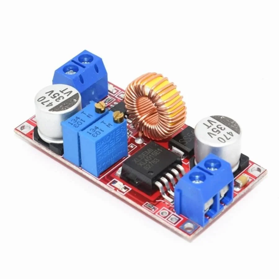
The XL4015 is one of the most widely used DC-DC step-down (buck) regulators. It is commonly sold as an adjustable module for converting 12 V or 24 V rails down to lower voltages such as 5 V.
It is popular because it is inexpensive, easy to use, and advertised as a high-current solution, often labeled as a “5A buck converter.”
However, most information available online stops at surface-level specifications.
A quick search for “xl4015” or “dc dc xl4015” typically returns product listings and short guides that repeat the same claims, with little explanation of how the circuit actually works, what limits real-world performance, or why many XL4015 modules overheat or show voltage drop in practice.
This gap creates a real problem for engineers, makers, and system designers.
When the XL4015 is treated as a drop-in, no-thinking power module, it is often pushed beyond its thermal, layout, or component limits.
The result is unstable output voltage, unexpected shutdowns, excessive heat, or outright module failure.
This guide takes a different approach. Instead of repeating XL4015 datasheet numbers, it explains how the XL4015 DC-DC buck converter operates, how a typical XL4015 module behaves in real builds, and how to use, adjust, and design around it correctly.
What Is the XL4015 DC-DC Buck Converter?
The XL4015 is a step-down (buck) switching regulator that converts a higher DC input voltage (Vin) into a lower, regulated DC output voltage (Vout).
It does this by rapidly switching a power transistor and smoothing the resulting waveform with an inductor and capacitors, rather than dissipating excess voltage as heat.
Buck vs linear regulator
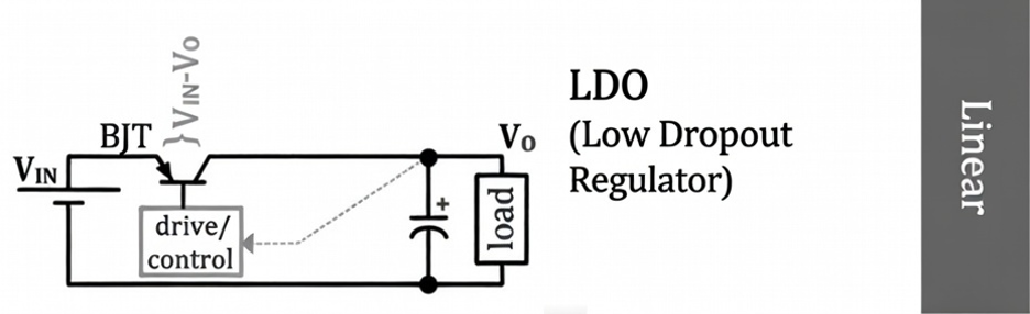
A linear regulator drops voltage by converting the difference between Vin and Vout directly into heat. This is simple, but inefficient at higher currents or large voltage drops.
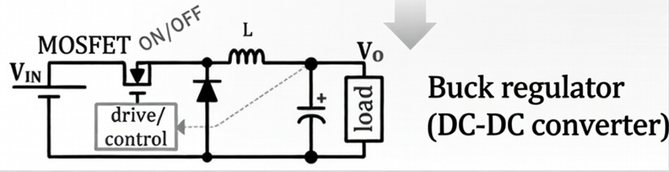
A buck converter like the XL4015 transfers energy through an inductor, making it far more efficient for stepping down from 12 V or 24 V rails to lower voltages at multi-amp loads.
Most XL4015 modules use a non-synchronous buck topology. They rely on an external Schottky diode during part of the switching cycle instead of a second MOSFET.
While this keeps the design low-cost, the diode’s forward voltage drop becomes a significant heat source at higher currents, which is why XL4015 modules tend to run hotter as load current increases.
XL4015 Electrical Specifications
Below are the typical electrical specifications most commonly associated with the XL4015.
Actual performance depends heavily on the specific XL4015 module, its components, and operating conditions. Typical XL4015 specifications are:
| Spec | Typical range (common listings) |
| Input voltage (Vin) | ~8–36 V (some modules advertise ~4–38 V) |
| Output voltage (Vout) | ~1.25 V up to ~32 V or higher, depending on module design |
| Switching frequency | ~180 kHz (fixed, commonly stated for XL4015) |
| Output current claim | “Up to 5 A” (conditional, not continuous by default) |
| Efficiency claim | “Up to 90–95%+” under ideal, best-case conditions |
These figures are often datasheet-level or marketing values. In practice, several limits come from the module rather than the IC itself:
- Thermal limits usually cap continuous output current well below the headline 5 A
- Inductor saturation and diode losses strongly affect usable current
- PCB layout and copper area determine how much heat can be safely dissipated
- Efficiency varies with Vin, Vout, and load current, and drops in worst-case conversions
Because of this, XL4015 specifications should be used as a starting point, then validated under real load and temperature conditions in your own design.
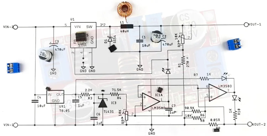
XL4015 Buck DC Circuit
To understand why XL4015 modules overheat, droop, or shut down, you need to look at the core buck DC XL4015 circuit itself.
Like all buck converters, its behavior is defined by high-frequency switching, energy storage, and feedback control.
Internal switch operation
Inside the XL4015 is a power switch that rapidly connects Vin to the inductor at a fixed switching frequency.
Regulation is achieved by adjusting the duty cycle, meaning how long the switch stays ON during each cycle. In an ideal buck converter, the relationship is approximately:
Vout ≈ Vin × duty cycle
Real XL4015 modules deviate from this ideal behavior due to diode voltage drop, switching losses, inductor resistance, and wiring losses, which all reduce efficiency and increase heat.
Role of the main parts
Inductor (energy storage and current smoothing)
When the switch turns ON, current through the inductor ramps up and energy is stored in its magnetic field.
When the switch turns OFF, the inductor releases that stored energy to keep current flowing into the load.
If the inductor saturates at high current, its ability to store energy collapses. Current rises sharply, regulation breaks down, and heat increases very quickly. This is a common failure point on low-quality XL4015 modules.
Schottky diode (current path during OFF time)
When the internal switch turns OFF, the inductor still forces current to flow. The Schottky diode provides the return path for that current.
Because this is a non-synchronous buck, all OFF-time current flows through the diode. At higher currents, the diode’s forward voltage drop translates directly into heat, making it one of the primary thermal bottlenecks in XL4015 designs.
Output capacitor (ripple reduction and transient support)
The output capacitor smooths voltage ripple and supplies fast current during sudden load changes.
Low-quality capacitors or high ESR result in higher ripple, poorer transient response, and visible voltage dip under load.
Feedback resistor network (voltage regulation)
A resistor divider feeds a scaled version of Vout into the feedback pin.
The XL4015 adjusts its duty cycle to keep this feedback voltage constant, which in turn keeps the output voltage regulated despite changes in load or input voltage.
Current flow during the ON/OFF cycle
- Switch ON: Vin powers the load and charges the inductor. Inductor current rises.
- Switch OFF: The inductor continues powering the load through the Schottky diode. Current remains continuous.
This is why both the inductor and the diode carry the full load current, and why their ratings, thermal behavior, and PCB layout have such a strong impact on XL4015 module performance in real applications.
How to Use XL4015 Step Down Charge Board
Using an XL4015 step down charge board correctly comes down to proper wiring, controlled setup, and thermal validation.
Most failures happen because the module is treated as a plug-and-play power brick rather than a switching regulator.
Connecting the input supply
Connect IN+ (VIN) to the positive terminal of your DC source and IN− (GND) to ground.
Use a supply with real current headroom. Buck converters draw pulsed input current, especially during load steps.
A weak adapter may show correct voltage at no load but sag badly under real current, causing instability and extra heating.
Connecting the load
Connect OUT+ to the load positive and OUT− to the load ground.
Keep leads short. Long wires add resistance and inductance, which increases voltage droop, ripple, and EMI.
At multi-amp loads, wiring quality matters almost as much as the module itself.
Initial voltage setup
Power the module with no load or a small dummy load. Measure Vout with a multimeter and adjust it to the required voltage.
This prevents accidental overvoltage damage to MCUs, sensors, or other sensitive electronics.
Load testing
Increase load gradually and observe:
- Output voltage stability
- Input voltage sag
- Temperature rise over time
A quick “it works” test is not enough. Many XL4015 modules fail only after heat builds up.
Thermal check
After 2–5 minutes at the intended load, check:
- XL4015 IC
- Schottky diode
- Inductor
If any of these are too hot to touch briefly, the module is beyond safe continuous operation.
XL4015 Efficiency and Thermal Limits
This is where the “5A rated” claim needs realistic interpretation. Even with high efficiency, power loss becomes heat, and heat rises quickly at higher current.
Primary heat sources are:
- Internal switch conduction and switching losses
- Diode conduction loss from the non-synchronous design
- Inductor copper loss and core saturation
Realistic continuous current ranges (typical low-cost modules)
| Cooling condition | Typical continuous current |
| No heatsink, minimal airflow | ~1.5 A to 2.5 A |
| Heatsink on IC, open air | ~2.5 A to 4 A |
| Heatsink with airflow | Can approach 4 A+ on better boards |
The Vin-to-Vout difference matters greatly. Stepping down from 24 V to 5 V at high current is a worst-case thermal condition.
Input and Output Capacitor Requirements
Capacitors are part of stability, ripple control, and transient response, not optional smoothing components.
Input capacitor ESR
The input capacitor supplies fast switching current locally. High ESR or long input leads cause Vin ripple, increasing noise and heat.
Output ripple under load
As load current increases, ripple current increases. If output capacitors are undersized or high-ESR, ripple rises and transient response degrades.
Practical capacitor improvements
Stability often improves by adding:
- A modest bulk capacitor near Vin
- Bulk plus a small ceramic capacitor near Vout
- Extra capacitance near the load if it is physically distant
Avoid extreme values. Add reasonable capacitance and validate behavior.
Wiring length and EMI
Long leads increase loop area and inductance, which raises EMI and can cause MCU resets, especially in Wi-Fi designs. Short wiring and clean grounding solve many unexplained issues.
Common XL4015 Design and Usage Mistakes
Most XL4015 problems are not caused by defective modules. They come from incorrect assumptions about how the module should be powered, loaded, and cooled.
Understanding these common mistakes will save time, prevent failures, and extend module life.
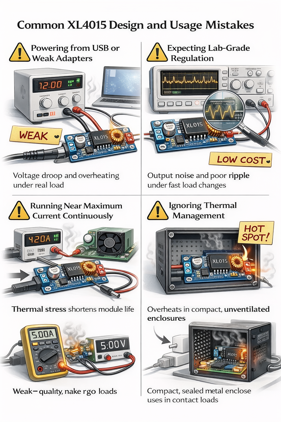
Powering from USB or weak adapters
One of the most common mistakes is powering an XL4015 module from USB ports or low-quality wall adapters.
These sources often provide correct voltage at no load but cannot handle the pulsed input current that a buck converter draws under real load.
When the input source sags:
- XL4015 increases duty cycle to compensate
- Input current rises further
- Losses increase
- Module heats up
This feedback loop leads to voltage instability and overheating. The XL4015 works best when stepping down from a solid higher-voltage rail such as a regulated 12 V or 24 V supply with adequate current margin.
Expecting lab-grade regulation
XL4015 modules are practical and cost-effective, but they are not precision laboratory power supplies. Output noise, ripple, and transient response vary significantly depending on:
- Capacitor quality
- Inductor performance
- PCB layout
- Wiring length
Expecting perfectly flat output under fast load changes often leads to disappointment. If your application requires very low ripple, tight transient control, or precise voltage accuracy, additional filtering or a higher-grade regulator is required.
Running near maximum current continuously
Many XL4015 modules will appear stable at high current for short periods. This creates a false sense of safety. Over time, thermal stress accumulates, especially in:
- Schottky diode
- Inductor
- IC package and PCB copper
Even if no immediate failure occurs, sustained operation near the upper limit significantly shortens module lifespan and increases the risk of sudden failure.
Ignoring thermal management
Thermal management is often treated as optional, but at multi-amp loads it is essential. Proper thermal planning includes:
- Good heatsink contact with the IC
- Airflow across the board
- Mounting orientation that allows heat to escape
- Awareness of hot spots near the diode and inductor
A module that works fine on an open bench may fail once enclosed or mounted vertically with no airflow.
Using XL4015 in battery-powered systems
Most XL4015 modules are not optimized for low idle or quiescent current. Even when lightly loaded, they can waste meaningful power. In battery-powered designs, this results in:
- Reduced standby time
- Unnecessary battery drain
- Lower overall system efficiency
For battery applications, modern low-IQ synchronous buck regulators are usually a better choice.
XL4015 vs Other Buck Converters
The XL4015 often appears alongside other popular buck solutions. Choosing the right one depends on current level, efficiency needs, board size, and thermal constraints, not just headline specifications.
XL4015 vs LM2596
The LM2596 is an older, widely used buck regulator and remains suitable for modest current applications. It is well understood, easy to source, and generally predictable.
The XL4015 is often selected when higher current capability is required. However, thermal limitations still dominate in real modules.
While XL4015 can handle more current on paper, poor cooling or low-quality components can erase that advantage quickly.
In short:
- LM2596: conservative, proven, moderate current
- XL4015: higher potential current, but requires better thermal handling
XL4015 vs MP1584
MP1584-based modules are compact and efficient, making them popular for space-constrained designs. They perform well at moderate currents and are often better suited for small embedded systems.
XL4015 boards are typically larger. This extra size can be beneficial at higher currents because:
- Larger inductors can be used
- More PCB copper is available for heat spreading
When board quality is good, XL4015 modules can outperform smaller regulators thermally, but they are not ideal for compact or enclosed designs.
If you are evaluating whether the XL4015 is the right choice, it is also worth reviewing how it differs from classic designs like the MC34063.
You can find a detailed comparison and deeper background here.
When XL4015 makes sense
The XL4015 is a good choice when:
- Stepping down from 12 V or 24 V rails
- Adjustable output voltage is required
- Board space is available
- Airflow or heatsinking can be provided
In these conditions, it offers a good balance between cost, simplicity, and usable current.
When You Should NOT Use XL4015
There are clear cases where an XL4015 module is the wrong tool.
Avoid XL4015 when you need:
- high-efficiency battery operation, where idle losses matter
- compact sealed enclosures with no airflow
- EMI-sensitive RF or precision analog systems
- very low quiescent current for long standby time
In these scenarios, better alternatives include:
- Modern synchronous buck regulators with lower losses
- Low-IQ buck converters for battery-powered products
- Dedicated charger ICs for battery charging applications
Typical Applications of XL4015
When used appropriately, XL4015 modules are reliable in many common roles.
They are widely used for:
- adjustable bench power supplies for prototyping
- constant-voltage LED drivers
- Arduino and MCU power rails (12 V or 24 V down to 5 V, then further regulation if needed)
- industrial control panels for relays, sensors, and auxiliary logic supplies
- lead-acid charging setups using CC/CV boards, with proper monitoring
For charging applications, always verify voltage limits, current limits, and temperature behavior over time. The presence of a “charge board” label does not replace proper electrical and thermal validation.
Final Thoughts
The XL4015 is popular for good reasons. It is affordable, widely available, and capable of stepping down 12 V or 24 V rails to lower voltages with far better efficiency than linear regulators.
When used within realistic limits, an XL4015 module can be a reliable and practical power solution for many designs.
Problems start when the module is treated as a generic “5A power board” instead of a switching regulator with real electrical and thermal constraints.
In real-world use, heat dissipation, component quality, wiring, and the Vin-to-Vout difference matter far more than the headline current rating.
If you understand how the buck circuit works, adjust the output correctly, validate behavior under load, and manage heat properly, the XL4015 behaves exactly as expected.
At Flywing Tech, we focus on helping engineers choose components with realistic expectations. When sourcing XL4015 modules, look beyond the “5A” label and pay attention to inductor size, diode rating, capacitor quality, and thermal design.
These details determine whether the module performs reliably in your application.
FAQ Section
How to use XL4015 safely?
Use a stable input supply, thick/short power wires, set Vout with a multimeter before connecting your device, then load-test and do a thermal check after a few minutes.
How to adjust XL4015 output voltage?
Power the module with no load, measure Vout, turn the potentiometer slowly, and confirm the voltage is stable under load afterward.
Can XL4015 really deliver 5A?
It can be possible under the right conditions, but many modules are limited by heat, diode losses, and inductor saturation. Treat 5A as conditional unless you verify temperature and stability in your exact setup.
Why does my XL4015 module overheat?
Common reasons are high current, big Vin-to-Vout drop, poor airflow, weak diode/inductor, thin wiring causing extra losses, or running near max current continuously.
Is XL4015 good for battery charging?
Only with the right CC/CV board design and careful settings. For lithium batteries especially, a proper charger/BMS is usually the safer choice unless you fully understand the charging profile and protection needs.
What is the XL4015 buck DC circuit?
It’s a non-synchronous buck converter: the IC switches Vin, the inductor stores/releases energy, the Schottky diode carries current during off-time, and capacitors plus feedback keep the output stable.