Introduction
Many electronic systems require high-voltage DC power supplies for their operation, such as industrial control systems and test and measurement equipment. These applications requires high voltage DC supply that must provide a stable output. Modern SMPS are used for such cases, but not always preferred due to their high efficiency!
In many cases, linear regulators are a suitable solution in high-voltage, low-current applications. In many practical cases, designers prioritize low output noise, predictable behavior, and circuit simplicity over efficiency. That is where TL783 voltage regulators come into play!
Linear regulators continue to play an important role in such environments. Unlike switching converters, linear regulators do not introduce high-frequency switching noise or electromagnetic interference, making them particularly attractive for sensitive analog circuits and bias supplies.
This technical guide focuses on the practical and safe use of the TL783 voltage regulator in high-voltage applications, with particular emphasis on designing a reliable 125 V linear power supply.
What is TL783 Voltage Regulator?
The TL783 voltage regulator is a type of linear regulator, meaning that these regulators dissipate the excess voltage between input and output in the form of heat. Linear regulators are often a good choice when the design requires low noise, low cost, simplicity, and power efficiency is not the main design parameter.
The TL783 is an adjustable high voltage regulator, meaning that the output voltage can be adjusted by setting the external resistor values. There are other adjustable regulators available, like LM317, AMS1117, LM338, and many more. However, these regulators have limited output voltage capability and are not suitable for designing applications that require high voltage for their operation. TL783 fulfills this requirement and can be adjusted to produce output voltage upto 125V with a maximum of 700mA current.
As the TL783 features a high output voltage of up to 125V, its thermal management is also crucial. Therefore, this device includes the thermal shutdown feature to protect the IC in case it draws more current than the specified limit. These high-voltage regulators mostly come in TO-220, PFM, and TO-263 packages.
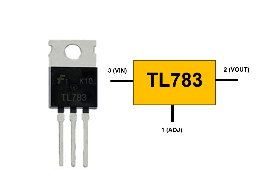
TL783 Voltage Regulator Pinout
This TL783 high voltage regulator has a very simple design that only includes 3 Pins: Input, Output, and Adjust Pin. By setting the two external resistors’ values, the designer can easily set the output voltage as per their design requirement. This section will include the pinout and formula to calculate the output voltage using the two external resistors. Apart from two external resistors, one input and one output decoupling capacitor of 10uF is also required to eliminate the voltage spikes and noise.
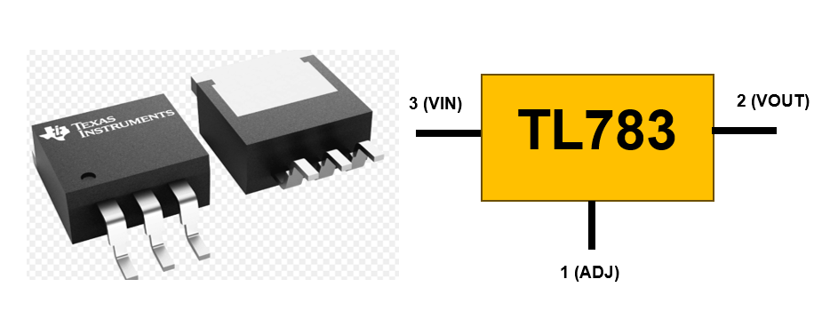
TL783 Pin Configuration

TL783 Output Voltage Formula
The designers often find it difficult to calculate the values of resistors for their desired output voltage. However, calculating the resistor value for your design application is pretty simple and can be calculated using the simple formula;
Vout =Vref ( 1 + R2 / R1 )
If we look at the datasheet of TL783, we come to know that the Vref is constant and set to 1.25V, and the recommended R1 value should be 82 ohms. Therefore, by knowing all these values, one can find the value of R2. For instance, for the 3V3 output voltage, the value of R2 should be;
R2 = 135 Ω
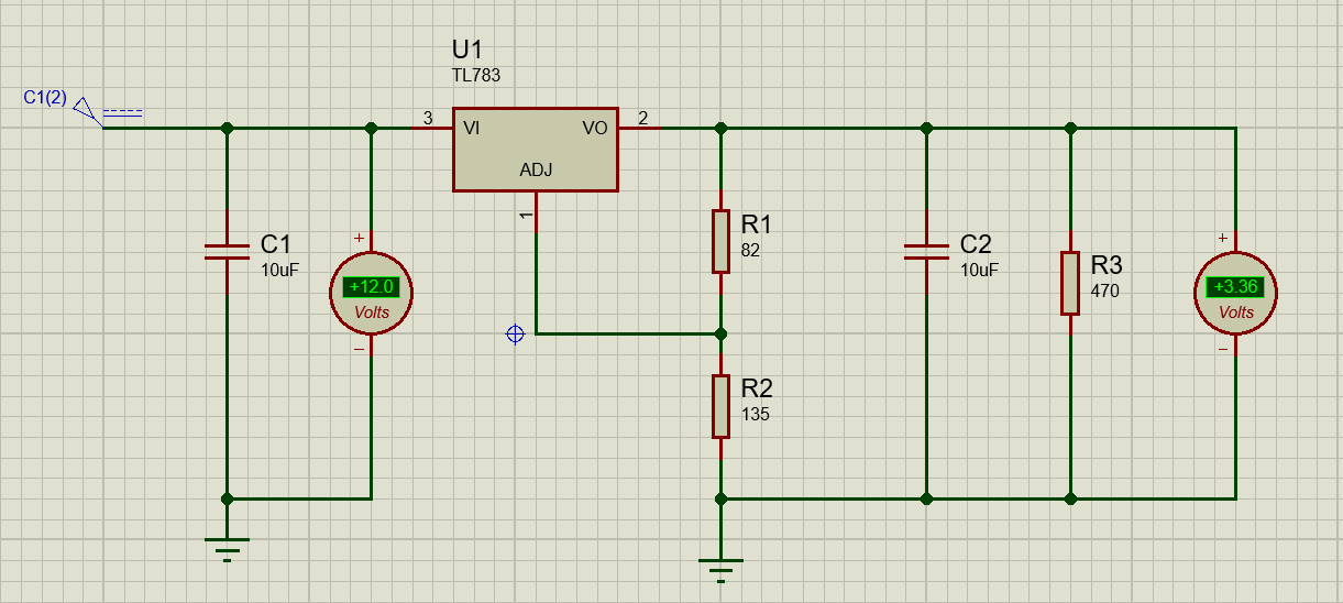
The typical circuit diagram of the TL783 voltage regulator, along with external resistors and decoupling capacitors are shown below.
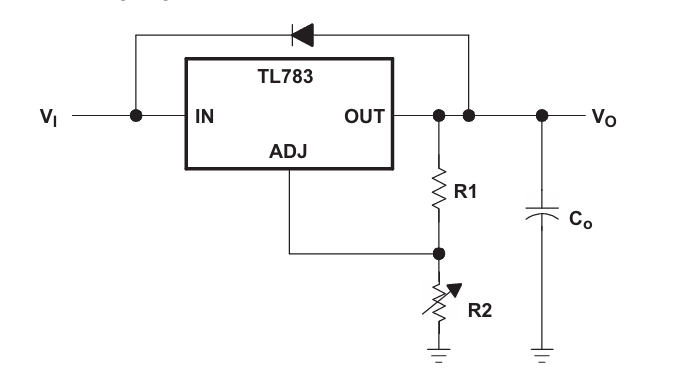
For PCB designers, the TL783 voltage regulator symbol and footprint link is also mentioned below to download and directly use them in your Altium and KiCad schematics.
Key Electrical Specifications of the TL783
When using any regulator or even any electronic module in the design, it is important to first know its key electrical specifications and ensure that these specifications will fulfill or match your design requirements. TL783 has some key electrical specifications that must be known to the designer to ensure that it meets their design requirements. The easiest way to know about the detailed electrical specifications is to consult the datasheet of TL783. However, this section will also explore and explain some key electrical specifications so that the reader can grasp what these specifications really mean!
High-Voltage Regulator Key Specifications Table
Key Electrical Specifications and Their Design Function
Basic Operating Principle of the TL783
The operating principle of the TL783 voltage regulator is important when designing or incorporating this regulator into your application. Understanding the operating principle helps the designers to evaluate whether this regulator will work perfectly in their design environment and under certain constraints. Therefore, this section will explain the operating principle of the TL783 voltage regulator.
The TL783 voltage regulator’s operating principle is more or less the same as that of other linear voltage regulators. It operates as a series-pass adjustable linear regulator that maintains the constant output voltage regardless of changes in the input size. TL783 basically consists of a precision reference voltage that generates the 1.25 volts, an internal error amplifier, and the pass transistor. The flow diagram of the working operation, along with a brief explanation, is also shown in the image below.
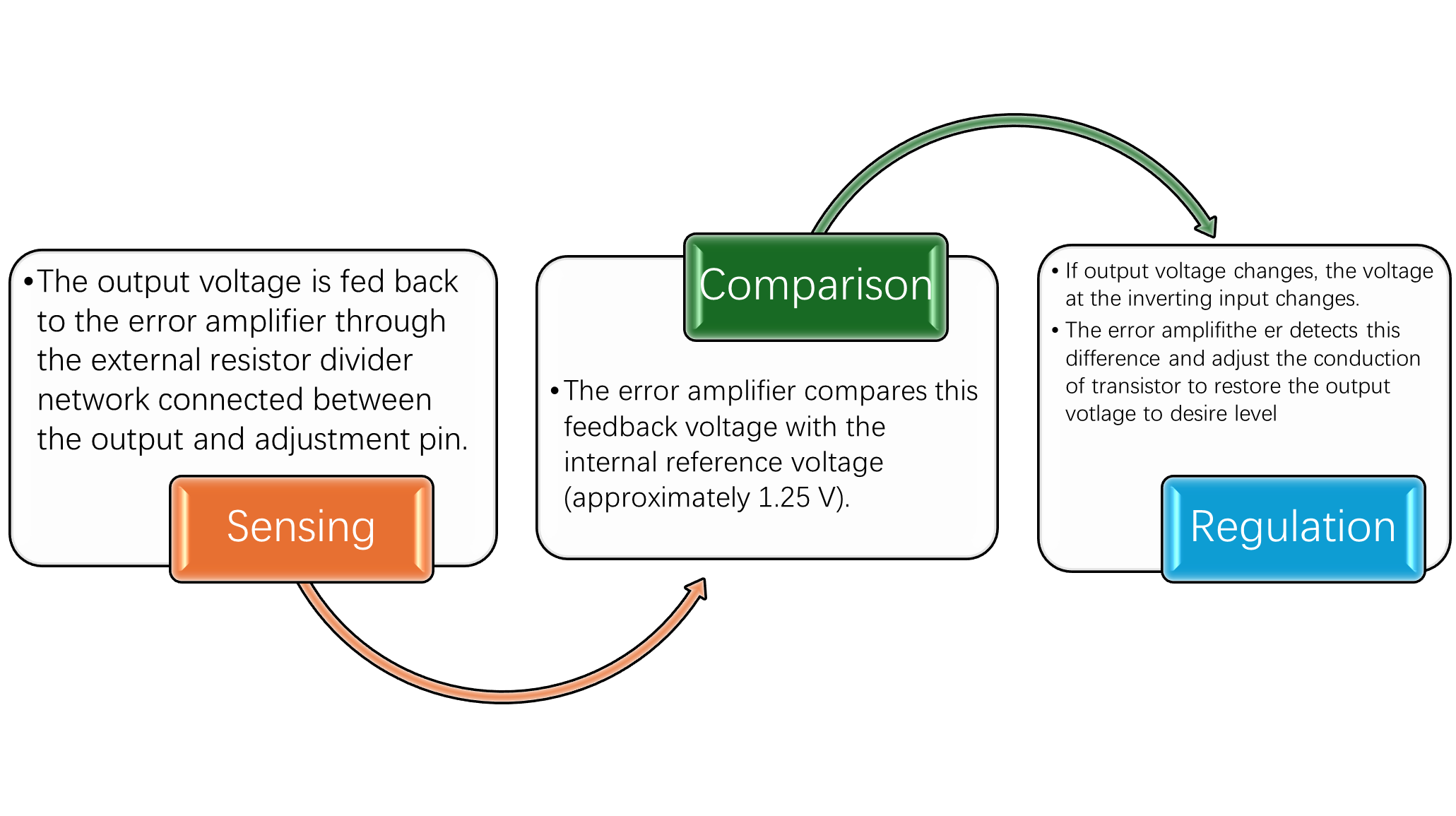
The switching regulators uses high frequency switching to control the output voltage. However, in linear regulators like TL783, the output is controlled using a series pass transistor that controls the voltage by operating its internal pass transistor in the linear region. The transistor effectively acts as a variable resistor, dropping the excess voltage between the input and output. Therefore, the power dissipated inside the device is directly proportional to:
PD = ( VIN − VOUT ) × ILOAD
At high input voltages, even modest load currents can result in significant internal power dissipation. This is why thermal design becomes critical in 125 V applications.
Basic TL783 125V Power Supply Configuration
The basic configuration of TL783 is the same as that of other linear voltage regulators, such as LM723, LM339, LM338, and AP7361. However, TL783 is specifically designed to operate safely at much higher voltages, i.e., 125V output. The regulator maintains a constant reference voltage between the OUT and ADJ pins, allowing the output voltage to be set using an external resistor divider network.
Typical Circuit Configuration
A standard TL783 power supply design typically includes:
Core Components
-TL783 Regulator IC
-Two resistors (R1, R2) for setting the output voltage
-Input filter capacitor (Cin) for noise filtering
-Output capacitor (Cout) for stability and transient improvement
-Protection diode for reverse discharge protection
Output Voltage Programming and Resistor Selection
The output of the TL783 voltage regulator is set using the simple resistor divider network. According to the datasheet, the recommended value of R1 is 82 ohms. Therefore, with the desired output voltage and R1 recommended value, we can easily find the R2 value for the desired output voltage.
3V3 volts are commonly used in embedded systems for powering the microcontrollers. Therefore, if the design requirements are to generate the 3V3 from the 12V. TL783 can easily be selected for this purpose because it can easily provide the 3V3 volts along with the desired current for the proper functioning of microcontroller. The TL783 can provide a maximum of 700mA current, and the microcontroller requires current in mA for its operation.
Therefore, if we use the datasheet recommended value for R1, which is 82 ohms, and the output voltage is 3V3, we will find the value of R2 using the equation;
Vout =Vref ( 1 + R2 / R1 )
3.3 = 1.25 ( 1 + R2 / 82 )
R2 = 135 Ω
Therefore, the R2 value is 135 ohms. By using these two resistor values, we can generate 3.3 volts. The typical circuit for generating the 3.3 volts from the 12V input using TL783 is simulated in proteus and its circuit is shown below.
Thermal Design: The Biggest TL783 Failure Point
Thermal management is one of the most critical design parameter especially for high voltage designs such as TL783. However, most designers overlook thermal management, which often leads to design failure. Therefore, whenever using TL783 in design for high output voltage, one must consider designing its thermal management.
The TL783 can handle high input-to-output voltage differences (up to 125 V), but this does not mean it can safely dissipate unlimited power. The device is limited by junction temperature and thermal resistance from the junction to the ambient. The TL783 typically operates up to about 125°C junction temperature (recommended), and the absolute maximum junction temperature is around 150°C, but operating near the maximum reduces reliability, as mentioned in the datasheet of TL783.
To make sure the design meets the thermal management ensure to use heatsink, large copper pours, thermal vias, and thick copper layers in your PCB design layout. One can also consider choosing the pre-regulator to minimize the voltage drop.
PCB Layout Guidelines for High-Voltage TL783 Designs
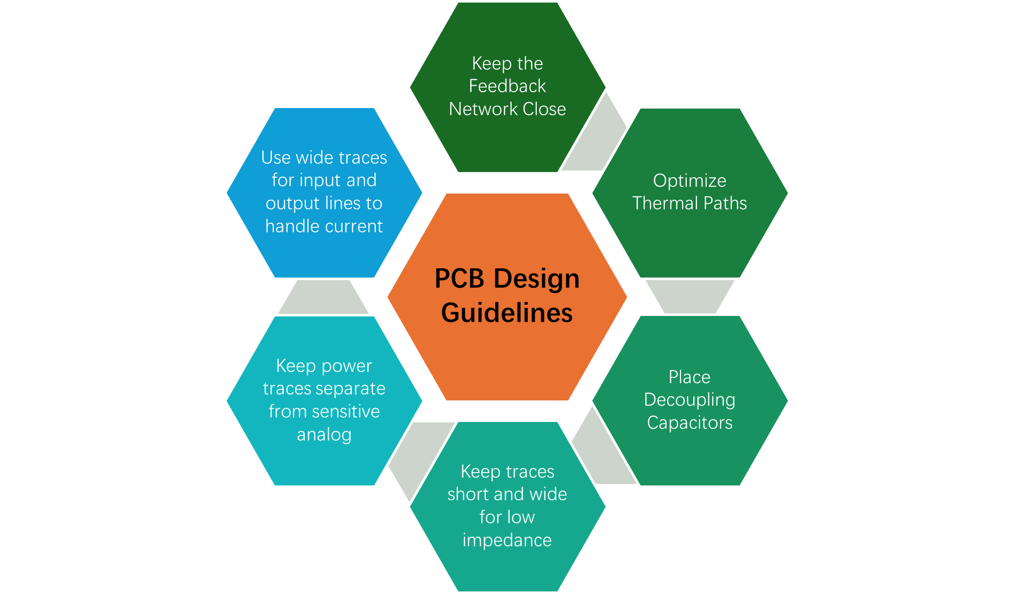
Using TL783 in your design for high voltage applications requires a proper layout of the PCB. Because when TL783 is being used to produce output voltage above 100V, most poor design fails due to excessive noise, improper thermal management, and poor PCB design practices. This section will explain the best PCB design guidelines when using TL783 in your design. Although the PCB design guidelines can also be used for any PCB design.
Keep the Feedback Network Close
The voltage-setting resistor divider between OUT and ADJ pins determines output voltage. Place R1 and R2 as close as possible to TL783 pins. Because, doing so will minimize trace lengths to reduce noise. Also, do not route the nosiy or high current signals near the ADJ pin of TL783.
Optimize Thermal Paths
The TL783 dissipates significant power in high-voltage applications. Therefore, use large copper pours connected the input, output, and GND pins. Also, Include thermal vias under the IC pad to transfer heat to inner layers and ensure enough copper area under the IC to reduce junction temperature rise.
Place Decoupling Capacitors
Decoupling capacitors are crucial for filtering the input noise. Therefore, place the input deocupling capacitor close to the IN pin to filter high-frequency noise and prevent voltage spikes. Also, place the output capacitor near the OUT pin to improve transient response and stability.
Common Circuit Applications with TL783 Voltage Regulator
The TL783 voltage regulator is widely used in consumer electronic, embedded applications, and other low to moderate current applications because it can only provide maximum of 700mA current.
High-Voltage Bias Supply for Analog Circuits
Many analog systems, including precision amplifiers, sensors, and measurement instruments, require a stable bias voltage often exceeding standard regulator limits. The TL783 is ideal for generating high-voltage bias rails (e.g., 80–125 V) with low output noise.
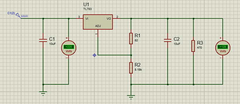
The simulation of 125 volt biasing power supply for an analog circuit is designed in Proteus. The R1 value is taken according to the datasheet recommended value, which is 82 ohms. The output voltage is 125; therefore, using these values, the R2 value has been calculated.
125 = 1.25 ( 1 + R2 / 82 )
R2 = 8120 Ω
High-Voltage Laboratory or Test Power Supply
The TL783 can also be used to build compact high-voltage DC power supplies for bench testing and prototyping. Designers can generate output voltages up to 125 V with simple external resistors and capacitors.
These power supplies are ideal for testing small high-voltage devices, charging circuits, and many more. They can also be combined with protection diodes and fuses for safe experimentation.
TL783 vs Alternative High-Voltage Regulators
For high-power applications with moderate current requirements, TL783 is among the best choices. However, TL783 is not the only option for designers. There are other alternatives with some other features that are also available. The designer should know these alternatives to make the correct decision for their design application. This section lists some alternatives to TL783 along with their strengths and limitations helps select the right solution for a specific application. Some of the best alternatives are NCP781, LR12, and LR8.
Comparison of Popular High-Voltage Linear Regulators
Conclusion
To sum up, TL783 is a versatile linear adjustable voltage regulator that offers high, clean output voltage. The output voltage is adjustable with the help of a resistor divider network, and it also features protection features that make it ideal for lab power supplies, analog bias circuits, and many more. However, the thermal management of these regulators and their best PCB design practices are important because they generate excess heat due to high voltage. This technical tutorial has covered TL783 voltage calculation using a resistor divider network, its thermal design and PCB design guidelines, and a power supply circuit with Proteus simulations. Understanding these will help the designers to effectively use TL783 in their design application.
Frequently Asked Questions (FAQ)
Yes, the TL783 can handle input-to-output differentials up to ~125 V, but power dissipation increases linearly with voltage drop. Designers must calculate thermal dissipation and use appropriate heatsinks and copper pours to avoid thermal shutdown
The TL783 alone is rated for ~700 mA. For higher currents add an external NPN or PNP pass transistor in series with the output.
TL783 is not optimized for battery-powered designs because It’s a linear regulator, so efficiency drops sharply at high input voltages.
High-voltage input spikes can damage the regulator. Therefore, add a fast-response ceramic capacitor (0.1 µF) at the input pin, and use a series TVS diode for protection.
Directly paralleling TL783s is not recommended because slight differences in internal reference voltages cause current hogging, However, to increase output current above 700mA use an external pass transistor.