As projects grow more advanced, many makers and engineers find that basic Arduino boards can’t keep up. They’re great for learning, but limited when you need more speed, memory, or connectivity. That’s where the STM32F103C8T6 “Blue Pill” comes in. It is a small, affordable 32-bit board that offers real power for serious projects.
The STM32 family has seen massive growth in recent years, with its market rising from about $1.9 billion in 2021 to $3.0 billion by 2025, driven by the boom in IoT and edge devices.
While Arduino still leads the beginner market, more developers are turning to STM32 boards like the Blue Pill for better performance at a lower cost.
In this article, we’ll explore what makes the STM32F103C8T6 Blue Pill so popular, how it compares to ATmega328P, its main specs and pinout, and the best ways to power, program, and use it in your next project.
What Is the STM32F103C8T6 (“Blue Pill”)?

The STM32F103C8T6, often called the “Blue Pill”, is a compact, low-cost 32-bit microcontroller board built around the ARM Cortex-M3 core running at up to 72 MHz.
It became popular because it bridges the gap between hobbyist and professional hardware. It offers far more performance than traditional 8-bit Arduino boards while still costing only $2 – $5 compared to over $20 for an official Arduino Uno.
Similar in size to an Arduino Nano, the Blue Pill fits neatly on a breadboard but delivers much greater speed, memory, and peripheral support.
Makers and engineers often use it when their projects outgrow the Uno’s limits. Unlike boards such as the ESP8266 or ESP32 variants, the Blue Pill doesn’t come with built-in Wi-Fi or an easy USB programming interface.
Instead, it focuses on raw processing power and real-time control, which makes it ideal for embedded systems that prioritize precision and responsiveness over connectivity.
STM32F103C8T6 Blue Pill Core Specifications
The STM32F103C8T6 Blue Pill delivers a strong balance of speed, memory, and connectivity in a compact and affordable form.
With 20 KB of SRAM and up to 128 KB of Flash memory, it easily handles larger programs, data buffers, and even RTOS-based applications.
Despite its capabilities, the Blue Pill remains energy-efficient, typically drawing around 25 mA in normal use and dropping to microamps in sleep mode.
Let’s quickly review the key specifications of the STM32F103C8T6 MCU and Blue Pill board:
| Feature | Details |
|---|---|
| CPU Core | 32-bit ARM Cortex-M3 @ 72 MHz |
| Flash Memory | 64 KB (often 128 KB in practice) |
| SRAM | 20 KB |
| GPIO Pins | 37 configurable I/O |
| Analog Inputs | 10 × 12-bit ADC channels (0–3.6 V) |
| Timers / PWM | 4 timers, up to 15 PWM outputs |
| Interfaces | 3 × UART, 2 × SPI, 2 × I²C, 1 × CAN, 1 × USB (FS) |
| Operating Voltage | 2.0 V – 3.6 V (typ. 3.3 V) |
| 5 V Tolerance | Most digital inputs 5 V-safe; analog pins not |
| Power Use | ~25 mA active, µA-level in sleep |
| Package | 48-pin LQFP MCU, 53 × 23 mm board |
| Regulator | 5 V → 3.3 V LDO (~300 mA output) |
| Clock Source | 8 MHz XTAL + 32.768 kHz RTC crystal |
| User Controls | 1 × LED (PC13), 1 × Reset button, 2 × Boot jumpers |
| Typical Cost | ≈ $2 – $4 USD (clone boards) |
For production-ready builds, the STM32F103C8T6TR is available through Flywing Technology in a 48-LQFP package with 64 KB Flash and ARM Cortex-M3 @ 72 MHz.
It supports both 2.5 V and 3.3 V operation and comes in tape-and-reel (T/R) packaging suitable for automated assembly.
Pinout & Block-Level View
The Blue Pill exposes most of the STM32F103C8T6’s 48 pins via two rows of headers. Below is a pinout and schematic diagram of the board, showing the function of each pin:
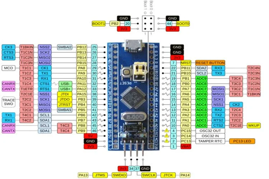

| Type | Pin Name(s) | Function / Description |
| Power | – 3.3 V
– 5 V – GND | 1. 3.3V Output: Regulated supply for the MCU core and peripherals.
2. 5V Input: Power from USB or external 5V source (regulated down to 3.3V). 3. GND: Common ground reference. |
| Analog Pins | PA0–PA7, PB0–PB1 | 10 × 12-bit ADC channels for analog input measurement. |
| I/O Pins | PA0–PA15, PB0–PB15, PC13–PC15 | 37 General-Purpose Input/Output (GPIO) pins for digital control and sensing. |
| External Interrupts | PA0–PA15, PB0–PB15, PC13–PC15 | Configurable interrupt-capable pins for event-driven applications. |
| PWM | PA0–PA3, PA6–PA10, PB0–PB1, PB6–PB9 | 15 Pulse-Width Modulation (PWM) outputs for motor, servo, or LED control. |
| Serial Communication (UART) | TX1, RX1, TX2, RX2, TX3, RX3 | 3 Universal Synchronous/Asynchronous Receiver-Transmitter (USART) interfaces for serial communication. |
| SPI | MISO0, MOSI0, SCK0, MISO1, MOSI1, SCK1, CS0 | 2 Serial Peripheral Interface (SPI) ports for fast data exchange with external modules. |
| CAN | CAN0TX, CAN0RX | Controller Area Network (CAN) pins for automotive or industrial communication (requires external transceiver). |
| I²C | SCL1, SDA1, SCL2, SDA2 | 2 Inter-Integrated Circuit (I²C) buses for connecting multiple peripherals with shared data and clock lines. |
| Built-in LED | PC13 | On-board status LED (active LOW). Useful for testing and debugging. |
Let’s talk about each type:
Power Pins
The board provides +5V, +3.3V, and GND pins on both sides. It can be powered either by a 5V source (via USB or an external supply) or directly from a regulated 3.3V line.
A small LDO regulator (TX6211B or AMS1117) converts 5V input to 3.3V for the MCU.
Reset and Boot Pins
The Blue Pill includes a RESET button and two small jumpers: BOOT0 and BOOT1.
These define which memory the MCU boots from:
- BOOT0 = 0, BOOT1 = 0: Boot from Main Flash (normal mode)
- BOOT0 = 1, BOOT1 = 0: Boot from System Memory (ST’s built-in serial bootloader for UART or USB DFU)
To flash firmware using the built-in bootloader, move BOOT0 to position 1, reset the board, and program via USART1 or USB DFU. After uploading, return BOOT0 to 0 before running your code.
Digital & Analog Pins
The Blue Pill breaks out most of Ports A, B, and C: PA0–PA7, PA9–PA15, PB0–PB11, and PC13–PC15 (plus VBAT)
That gives roughly 30 usable GPIO pins, with 10 analog-capable inputs (on PA0–PA7, PB0, PB1).
Each analog input supports 12-bit resolution, offering more precise readings than the Arduino’s 10-bit ADC. However, analog pins are not 5V tolerant so applying more than 3.6V may damage the MCU.
Many digital pins, however, are 5V-tolerant (FT). Examples include PA9/PA10 (UART1) and PB6/PB7 (I²C1). Always verify tolerance in the official datasheet before connecting 5V devices.
Communication Interfaces
The Blue Pill supports a rich set of interfaces:
- USART (3x): PA9/PA10 (USART1), PA2/PA3 (USART2), PB10/PB11 (USART3)
- SPI (2x): SPI1 on PA5/PA6/PA7, SPI2 on PB13/PB14/PB15
- I²C (2x): I²C1 on PB6/PB7, I²C2 on PB10/PB11 (shared with USART3)
- CAN Bus: PA11 (RX) and PA12 (TX) — requires an external CAN transceiver
- USB FS: shares the same PA11 (D−) and PA12 (D+) pins; includes a pull-up resistor on D+ for detection
External pull-ups are required for I²C lines, and USB functionality typically requires loading a USB-enabled bootloader or firmware.
Timers & PWM
The STM32F103C8T6 includes four 16-bit timers (TIM2–TIM5) plus an advanced control timer (TIM1) for motor or PWM control.
You can output up to 15 PWM signals, far more than the six available on an Arduino Uno.
Common channels include PA0–PA3 (TIM2), PB6–PB7 (TIM4), and PA8–PA11 (TIM1).
The advanced timer supports complementary outputs and dead-time insertion, ideal for motor drivers, servos, or LED dimming applications.
Debug Interface (SWD)
The Blue Pill supports Serial Wire Debug (SWD) for programming and real-time debugging.
Pins PA13 (SWDIO) and PA14 (SWDCLK) connect to tools like ST-Link V2.
Some boards include a dedicated 4- or 6-pin header; if not, you can connect directly via jumpers. SWD enables direct flashing (no bootloader needed) and advanced debugging.
How to Program the Blue Pill
Unlike an official Arduino Uno, the Blue Pill doesn’t ship with an Arduino bootloader or a “plug-and-play” USB programmer.
Out of the box, the STM32F103C8T6 relies on its factory ROM (System Memory) bootloader, which you enter with the BOOT0/BOOT1 pins.
That ROM loader supports UART (USART) programming on this device; USB DFU is not provided in ROM for the F103C8, so using the on-board USB port for uploads requires a custom USB bootloader or a debug probe (ST-Link).
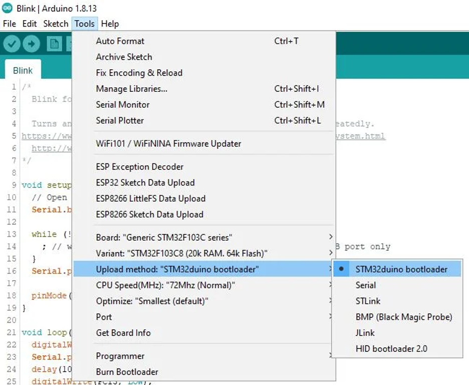
Option 1: Arduino IDE (STM32duino core)
If you like the Arduino workflow, install STM32 boards support (STM32duino) via Boards Manager. Then you can write sketches as usual and choose one of these upload methods:
A) USB-to-Serial (USART1) via ROM bootloader
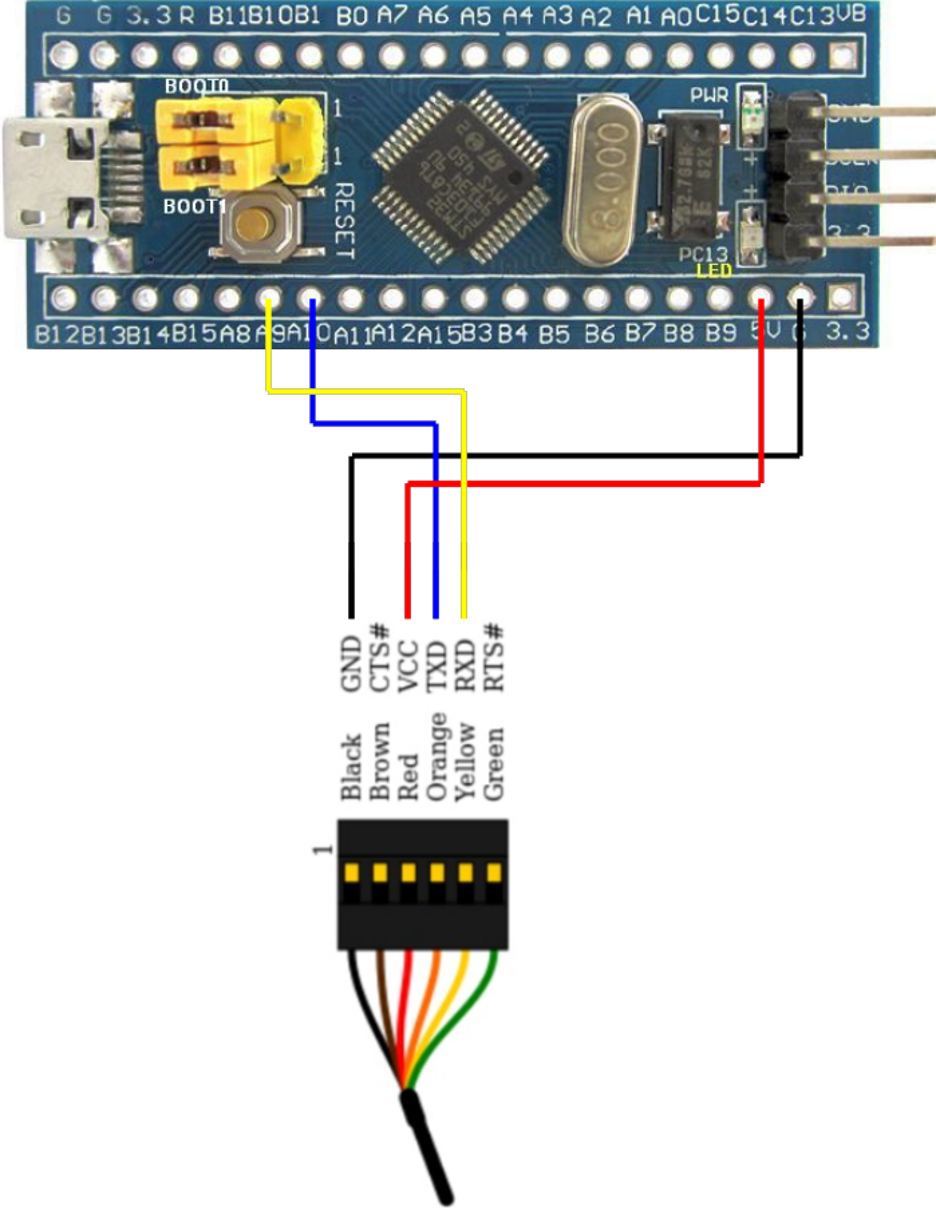
- Connect a USB-TTL adapter to PA9 (TX1) and PA10 (RX1).
- Set BOOT0 = 1 (BOOT1 stays 0 on typical Blue Pill), reset the board; it enters the System Memory bootloader.
- In Arduino IDE, select the serial upload method; the tool sends your program over UART and writes Flash.
- Set BOOT0 back to 0 and reset to run your sketch. This path uses ST’s built-in loader.
B) USB DFU (with a custom bootloader, e.g., “Maple”/STM32duino)
- First flash a USB DFU bootloader once (via Serial or ST-Link).
- After that, the Blue Pill enumerates over USB for direct uploads from the IDE (select the STM32duino bootloader/DFU upload method).
You’re not using the ROM USB bootloader here—the F103C8 ROM lacks USB DFU. You’re installing a user bootloader in Flash that provides USB updates.
Many Arduino libraries work on STM32, but AVR-specific code (direct register hacks, inline AVR asm) may need STM32-friendly alternatives.
Option 2: ST-Link + STM32CubeIDE (HAL/LL/CMSIS)
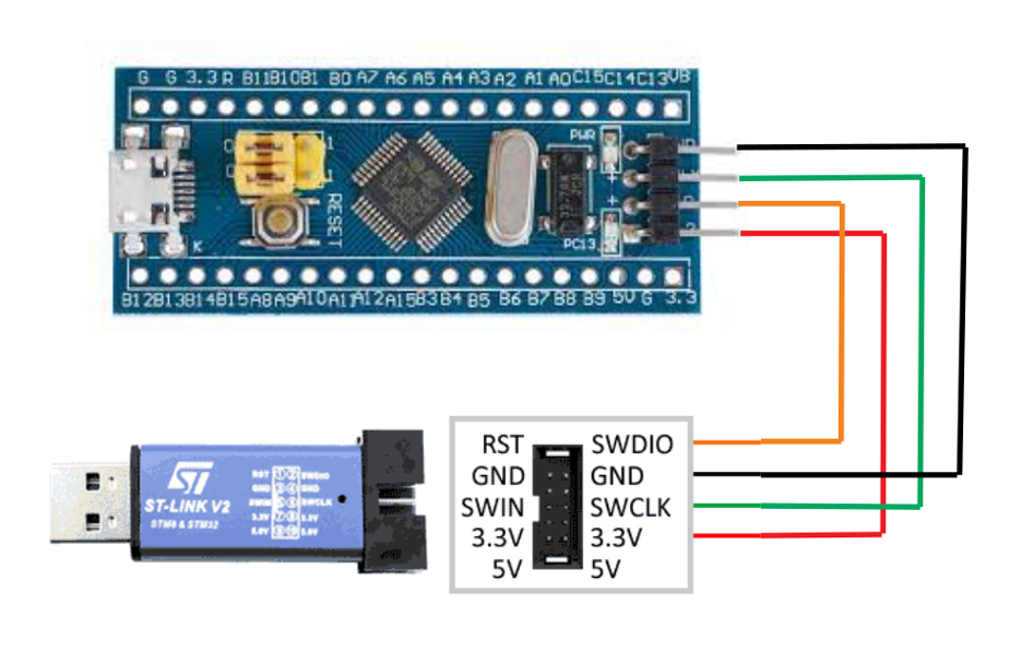
This is the most robust, “pro” setup.
- Connect an ST-Link probe to SWDIO (PA13), SWCLK (PA14), 3V3, and GND.
- Use STM32CubeIDE (or Keil/IAR/VS Code + PlatformIO) to build, flash, and debug with breakpoints and memory watch—no boot jumpers required (BOOT0=0 the whole time)
This route uses ST’s HAL/LL/CMSIS drivers and gives you full control over clocks, pin muxing, and peripherals (CubeMX inside CubeIDE can autogenerate init code).
Quick Start: LED Blink on Blue Pill (Two Ways)
One of the best ways to confirm your Blue Pill setup is working is with the classic “blink an LED” test.
On this board, the on-board LED is connected to pin PC13, and it’s active-LOW meaning the LED lights up when the pin is driven LOW, and turns off when driven HIGH.
There are two common ways to try this: with the Arduino IDE (STM32duino core) or with STM32CubeIDE using HAL.
Blink Using Arduino ( STM32duino Core )
Once you’ve installed the STM32 boards package in the Arduino IDE, open a new sketch and paste this code:
// Define LED pin
const int LEDPIN = PC13;  // On-board LED is on PC13

void setup() {

  pinMode(LEDPIN, OUTPUT);

}

void loop() {

  digitalWrite(LEDPIN, LOW);   // LED ON (active low)

  delay(500);

  digitalWrite(LEDPIN, HIGH);  // LED OFF

  delay(500);

}
Upload the sketch via your chosen method: Serial, DFU bootloader, or ST-Link. The LED should blink once per second. Here are some instructions:
- Make sure the correct board is selected, e.g. “BluePill F103C8” (or F103CB if yours has 128 KB Flash).
- Set BOOT0 = 0 after programming; otherwise, the MCU may stay in bootloader mode.
- The constant LED_BUILTIN also works on many cores, since the LED pin (PC13) matches older Maple board definitions.
If the LED doesn’t blink, double-check your upload method in Tools → Upload Method and verify the serial adapter or ST-Link connection.
Blink Using STM32 HAL (CubeIDE / Bare-Metal Code)
If you’re using STM32CubeIDE, you can perform the same blink test using the HAL library. Here’s a minimal example that configures PC13 as an output and toggles it:
/* In main.c, after HAL_Init(); and SystemClock_Config(); */

__HAL_RCC_GPIOC_CLK_ENABLE();

GPIO_InitTypeDef GPIO_InitStruct = {0};

GPIO_InitStruct.Pin = GPIO_PIN_13;

GPIO_InitStruct.Mode = GPIO_MODE_OUTPUT_PP;

GPIO_InitStruct.Pull = GPIO_NOPULL;

GPIO_InitStruct.Speed = GPIO_SPEED_FREQ_LOW;

HAL_GPIO_Init(GPIOC, &GPIO_InitStruct);

/* Main loop */

while (1) {

  HAL_GPIO_WritePin(GPIOC, GPIO_PIN_13, GPIO_PIN_RESET); // LED ON

  HAL_Delay(500);

  HAL_GPIO_WritePin(GPIOC, GPIO_PIN_13, GPIO_PIN_SET);   // LED OFF

  HAL_Delay(500);

}
CubeIDE (or CubeMX-generated code) takes care of startup configuration, so you can simply build and flash using ST-Link or STM32CubeProgrammer.
If everything is connected correctly, the LED on PC13 should blink continuously.
Once You See It Blink, you’ve confirmed your board, bootloader, and toolchain are all functioning properly.
STM32F103C8T6 vs ATmega328P
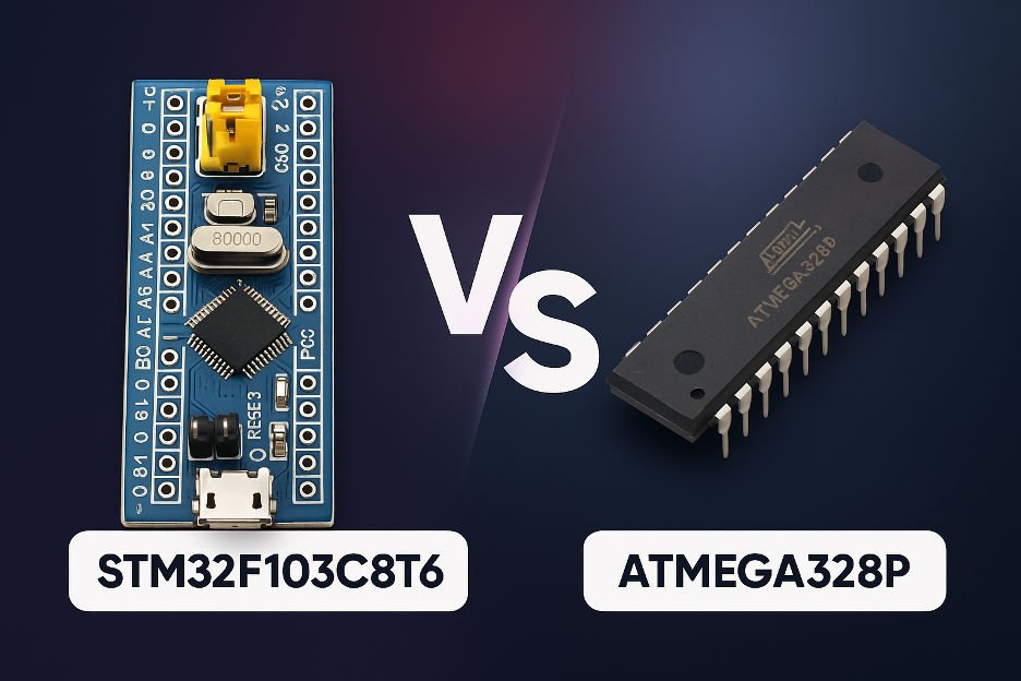
The STM32F103C8T6 “Blue Pill” and the ATmega328P (the microcontroller inside the Arduino Uno and Nano) are two of the most popular chips among makers and hobbyists.
Both are affordable, widely supported, and great for learning embedded development but they’re built for very different levels of performance.
The STM32F103C8T6 runs on a 32-bit ARM Cortex-M3 core at 72 MHz, while the ATmega328P uses an 8-bit AVR running at 16 MHz.
That difference alone gives the STM32 roughly 4–5× higher clock speed and a much more capable instruction set for complex math, multitasking, or real-time control.
In simple terms:
- Arduino Uno (ATmega328P) is easier to start with as it just works out of the box.
- Blue Pill (STM32F103C8T6) is faster, smarter, and cheaper but requires a bit more setup.
Specification Comparison

Lets dive into the details:
Performance
The STM32 is far faster, has 10× more RAM, and supports more advanced peripherals. It is ideal for real-time control, robotics, or data-intensive applications.
Analog Precision
STM32’s 12-bit ADC offers four times finer resolution than Arduino’s 10-bit ADC. This makes it better for sensors or audio processing.
Connectivity
With multiple UARTs, SPI, I²C, and built-in USB and CAN, the Blue Pill can connect to many devices simultaneously, no need for extra shields or chips.
Ease of Use
Arduino wins here. Its ecosystem, beginner-friendly IDE, and plug-and-play USB support make it unbeatable for getting started quickly.
Voltage Compatibility
The Arduino runs at 5 V logic, which is compatible with older sensors and modules.
The STM32 runs at 3.3 V but most digital pins are 5 V-tolerant, so mixing isn’t usually a problem.
Debugging
The STM32 supports hardware debugging (SWD) through ST-Link — something Arduino boards lack natively.
When to Use Each
Choose Arduino Uno / Nano (ATmega328P) if:
- You’re a beginner or teaching embedded basics.
- Your project is simple — LEDs, small sensors, or basic automation.
- You use 5 V sensors or existing Arduino shields.
- You want maximum community support and plug-and-play development.
- You need built-in EEPROM for small data storage.
Choose STM32F103C8T6 “Blue Pill” if:
- You need more processing power, memory, or multitasking.
- You want to connect multiple devices (UART, SPI, I²C, CAN, USB).
- Your project requires precision analog readings or high-speed PWM.
- You’re planning to use RTOS or advanced frameworks.
- You want professional-grade debugging via ST-Link.
- You’re building multiple units and need low-cost scalability.
If you’re learning or building quick prototypes, start with Arduino.
If you’re scaling up into real-time, performance-critical, or professional projects, the STM32F103C8T6 (Blue Pill) delivers far more power per dollar.
Final Thoughts
If you’ve outgrown entry-level Arduino boards but don’t want to jump straight into expensive, high-end kits, the STM32F103C8T6 “Blue Pill” is a sweet spot.
It delivers real 32-bit performance, plenty of I/O, and pro-grade interfaces (USB, CAN, multiple UART/SPI/I²C) at a price that scales for production.
Yes—there’s a little more setup, and clone quality can vary but once you’ve got your toolchain in place (Arduino/STM32duino or ST-Link + CubeIDE), you’ll get more headroom per dollar for control loops, sensing, and data handling than classic 8-bit boards can offer.
With those checks, the Blue Pill is a reliable, low-cost foundation for education kits, small robotics, industrial sensor nodes, and early product runs.
For sourcing authentic STM32F103C8T6 components, Flywing Technology offers verified STMicroelectronics parts, competitive bulk pricing, and ready-to-ship stock for both tray (C8T6) and tape-and-reel (C8T6TR) versions.
Their catalog supports engineers, educators, and OEMs looking to transition from prototypes to scalable production without sacrificing reliability or compliance.
🔗 Explore available inventory here: Flywing Tech STM32F103C8T6 Catalog
Frequently Asked Questions (FAQs)
1) Is the Blue Pill a drop-in replacement for an Arduino Uno?
Not physically or electrically. It’s 3.3 V logic (many pins 5 V-tolerant for inputs) and a different pin layout. Code can be ported (Arduino core exists), but libraries that use AVR-specific registers need STM32-compatible versions.
2) How do I program it the first time?
Three common ways:
- ST-Link (SWD): Fast, reliable, with debugging.
- UART bootloader: USB-to-TTL on PA9/PA10 with BOOT0=1 for flashing, then back to 0 to run.
- USB DFU bootloader: Flash a user bootloader once (e.g., Maple/STM32duino), then upload via onboard USB.
3) Does it really have 64 KB or 128 KB of Flash?
Officially 64 KB (C8), but many boards ship with chips that have 128 KB. If your tools support it, select the 128 KB (CB) variant to use the extra space.
4) Can I power it from USB and an external 5 V at the same time?
No. There’s no power-OR circuit. Don’t double-power the 5 V rail (USB + external). Use one source at a time, or power the 3.3 V rail directly with a regulated supply.
5) Are the pins 5 V-tolerant?
Many digital inputs are 5 V-tolerant; analog (ADC) pins are not. Never feed >3.3 V into ADC inputs. Outputs are 3.3 V only—use level shifters if a device needs 5 V HIGH.
6) Why doesn’t my PC see the Blue Pill over USB for uploads?
The F103C8 doesn’t have USB DFU in ROM. You either need to install a USB bootloader first or program via ST-Link/UART. Also confirm the USB D+ pull-up is 1.5 kΩ on your board.
7) Typical current draw and low-power tips?
Expect ~25–30 mA in simple active use. You can reach µA-level sleep by disabling LEDs/regulator loads and using Stop/Standby modes. Avoid active USB if you need deep sleep.
8) What’s the fastest way to get a “blink” working?
- Arduino IDE + STM32 boards package → select Blue Pill, upload the PC13 blink via Serial/DFU/ST-Link.
- Or CubeIDE + ST-Link → generate GPIO init in CubeMX, toggle PC13 in a loop.
9) Any clone-board “gotchas” to check when sourcing?
Yes: correct USB D+ resistor (1.5 kΩ), stable 3.3 V regulator, crystal quality, and genuine/grade-matched MCU. Ask suppliers for lot-level tests, programming samples, and photo BOMs.
10) When should I choose Blue Pill vs Uno in a project?
- Uno: teaching, very simple builds, 5 V shields, and maximum beginner ease.
- Blue Pill: performance, precision ADC, multiple serial buses, USB/CAN, RTOS, and cost-effective scaling for small production.