Introduction
In digital and analog circuit design, the LM317 is one of the widely used adjustable voltage regulators. The primary function of these regulators is to provide a constant and stable DC voltage. These regulators employ internal current limiting, thermal shutdown, and safe area compensation, making them ideal for a wide range of applications from power supplies to more complex electronic systems.
The LM317 comes as a three-terminal device with one input, one output, and only two external resistors to set the output voltage. The LM317 comes in different ranges, typically with an output voltage range of between 1.2V to 37V and a current handling capacity up to 1.5A. Their design features and ability to easily integrate into a circuit make them suitable for all engineers and design professionals.
LM317 Role in Power Regulation?
LM317 adjustable voltage regulators replace the traditional fixed regulators, such as 7805. The disadvantage of these regulators is their fixed output voltage. Whereas the LM317 output voltage can be adjusted by the appropriate selection of external resistors, resulting in flexible and custom voltage selection. The LM317 output voltage can be adjusted by appropriately selecting external resistors, allowing flexible and custom voltage settings. The electronic circuits are power sensitive, and any minor change in the output power can cause the circuit to fail. The output regulation of LM317 is excellent regardless of changes in load current.
| Parameter | Value | Importance in Circuit Design |
|---|---|---|
| Output Voltage Range | 1.2V to 37V | Any voltage level can be achieved with just two external resistors. |
| Output Current | Up to 1.5 Amps | Capable of handling medium power loads. |
| Line Regulation | 0.01%/Volt | Regardless of a change in input, it ensures stability. |
| Load Regulation | 0.1% | Provide constant voltage under varying loads. |
| Dropout Voltage | Approximately 3V | It is important to consider when choosing an input voltage. |
LM317 PIN Configuration
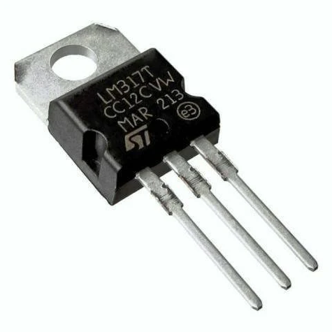
LM317 voltage regulators consist of only three terminals, but they come in many different packages, including SOT-223, TO-220, and TO-3. Among all types, the TO-220 package is the most commonly used in printed circuit board designs.
| PIN Number | PIN Name | Function |
|---|---|---|
| PIN 1 | Adjust | It adjusts the output voltage with the help of two external resistors. |
| PIN 2 | Vout | Provides constant and regulated output voltage. |
| PIN 3 | Vin | Gets an unregulated input voltage. |
LM317 Circuit Design
As we know, the LM317 consists of three terminals. The circuit design consists of two external resistors to adjust the output voltage to the desired value. One input capacitor is used in the LM317 circuit design to filter the high-frequency noise and improve the transient response. Another capacitor is used at the output side to improve the load regulation by reducing the output ripple. In the printed circuit board design, it is recommended to place the input capacitor near to input PIN to minimize the inductive effects.
| Typical values of input/output capacitors | Value |
|---|---|
| Input capacitor | 0.1uF (read datasheet recommended) |
| Output capacitor | 1-100 uF (Read datasheet recommended) |
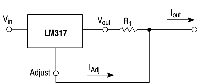
The standard circuit of LM317 is shown below.

The output voltage can be determined with the help of two external resistor values and the current flowing through PIN 1 of LM317. The R1 resistor is usually fixed and its value is 240Ω. This is done to maintain a minimum load current which is 5mA.
$$5V = 1.25V \left(1 + \frac{R_2}{240}\right) $$
Note: Note that to maintain output regulation, the input voltage must be at least 3 V higher than the output voltage. This is important because it is the dropout voltages.
Common Circuit Applications with LM317
The LM317 voltage regulator is widely use in electronic circuit design applications. In this section, we will cover some of the LM317 voltage regulator application circuits with their design steps.
- Constant Voltage Regulator (12.7V – 9V)
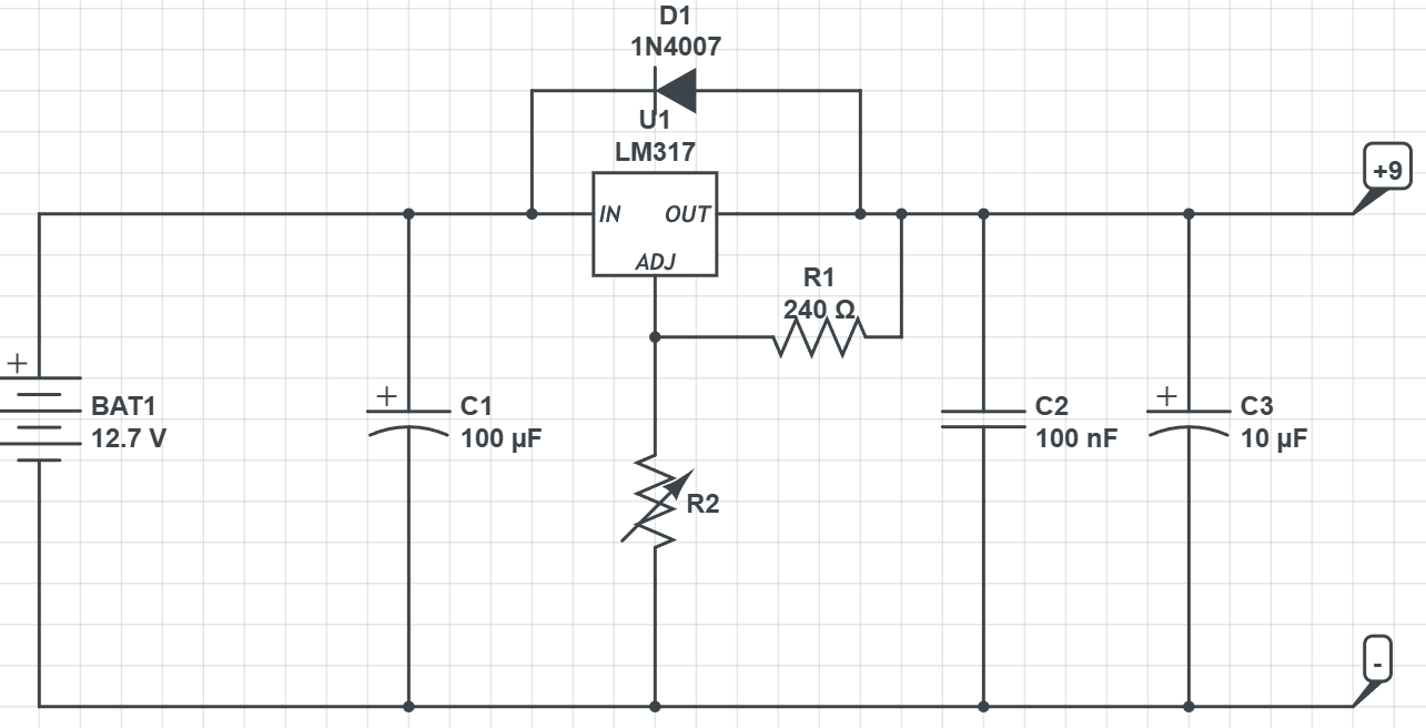
The constant voltage regulator circuit converts the 12.7 Volts of battery to a constant 9V output using the LM317 voltage regulator. The purpose of constant voltage regulator circuit is to maintain +9V constant regulated output. The external resistor network decide the output voltage. The formula to find the resistor R2 value is;
- Constant Current Regulator
The LM317 can also function as a constant current regulator, with the output current controlled and regulated using resistor R1. To regulate the constant 1A current at the output.
Therefore, to regulate the constant 1A current at the output of LM317, the R1 value should be 1.25 ohms.
- Negative Voltage Regulator
The negative voltage is a type of adjustable regulator that provides the stable and regulated negative output. There are separate ICs available for negative votlage regulation like LM337. However, one can also use the LM317 as a negative voltage regulator by simply inverting the resistor network and wiring the negative terminal of input supply with input PIN of LM317 as shown in figure.

The output voltage formula of negative voltage regulater is change from the positive voltage regulator.
$$V_{out} = -1.25V \left(1 + \frac{R_2}{R_1}\right) $$
How to design with LM317
The LM317 is a voltage regulator that can provide the output regulation between 1.25V and 37V. In order to design with LM317, you must go through the following steps.
Know Your Design Requirements
Before you start your design, first identify the design requirements such as output voltage, load current, input voltage range, and allowable voltage ripples. Once you complete the requirements, record them and proceed to the next step.
Calculate the Design Parameters
Now, you have your design requirements. It’s time to calculate the design parameters.
- At first, know what should be the output voltage of your LM317 and calculate it using the formula.
- The second design parameter is calculating the resistor R2 for the desired output voltage using the above equation.
- Choose the output voltage such that the difference between the input and output voltage must be greater than 3V (Dropout Voltage); otherwise, the regulation will fail.
- Choose the appropriate values of input and output capacitors and consult the manufacturer’s datasheet.
Test and Validate Your Design
Once you calculate the design parameters, simulate the circuit design in appropriate software. If the results are as expected, design the circuit board, test, and validate your design.
Heat Sink Calculation
The dropout voltage of LM317 is 3V. The regulator convert the dropout voltage into heat, results in excellent power regulation. The converted heat requires thermal management to avoid excessive heat. One can calculate the heat generated using the equations as follows;
$$P = 1.25V \left(V_{in} – V_{out}\right) \times I_load$$
To determine the required heart sink size,
$$\theta_{sa} = \frac{T_{j,\max} – T_{a2}}{P}- \theta_{jc} – \theta_{cs} $$
Where:
$T_{j}$, max is Max junction temperature
$T_{a}$ is the Ambient temperature
$\theta_{jc}$ is Junction case thermal resistance
$\theta_{cs}$ Case–sink thermal resistance
Simulation Results of LM317
In this section, I have simulated the 115VAC-12V power supply circuit design using the LM317 voltage regulator. A step-down transformer converts the 115 VAC input voltage. The step-down output is rectified using a full-bridge rectifier to an unregulated DC. The 17V unregulated voltage is fed into the input PIN of LM317, and it generates an output regulated +12V output voltage. You can convert the voltage by setting the two external resistor values. The figures below show the simulation circuit and result waveforms. The output graphs show the input AC waveform along with the unregulated and regulated output waveforms.

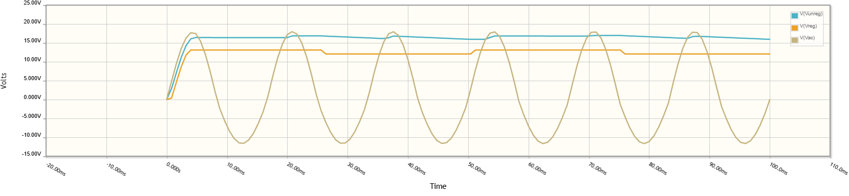
Output voltage waveform of the LM317 voltage regulator.
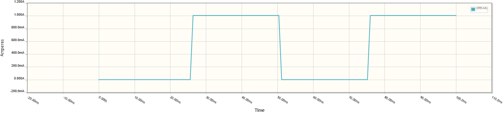
Output current waveform of the LM317 voltage regulator
In the output voltage waveform, you can see that the input 115VAC is a sinosoidal waveform and it is step down using the step down transformer. The output alternating voltage at the secondary side is pass through a full bridge rectifier that makes the output pulsating DC output. The blue output waveform shows the unregulated output that is pulsating and has ripple content. The unregulated output is given to the input terminal of LM317 and with the help of external resistors desired output of 12V is maintained. The yellow color output waveform indicates the regulated output with minimum ripple content and is sutiable for devices that required constant 12V output voltage. The internal circuit of LM317 consist of a feedback mechanism that continously compares that output waveform with the desired/reference output waveform and adjust the output current accordingly to compensate for any voltage fluctuations.
Tips and Precautions of Using the LM317
To get the maximum out of the LM317 adjustable voltage regulator, there are some tips and precautions to help you ensure optimum performance of your circuit design.
- Always make sure that the difference between your desired output and input voltage is greater than 3V to avoid regulation failure.
- Always refer to the datasheet of your LM317 voltage regulator so that you can choose the correct input and output capacitors.
- Always calculate the heat dissipation of your LM317 circuit design. If it is greater than 1 watt, you will need to add a heatsink.
- To avoid reverse polarity faults, use a protection diode in your circuit design.
- For instance, in the battery charger circuit, if you do not place the output capacitor. It will cause unstable voltage. Thus, adding a 10uF capacitor will resolve the problem.
Conclusion
In conclusion, designers widely use the LM317 adjustable voltage regulator for a wide range of applications in electronic circuit design. Unlike the traditional 780X fixed voltage regulators, these regulators offer a flexible output voltage range, making them a popular choice among professionals. The understanding of these regulators’ PIN configuration, output voltage calculations, and other design parameter calculations is important for engineers to design state-of-the-art electronic solutions.
Frequently Asked Questions (FAQ)
Q1. Can I use LM317 for my battery charging circuit?
Yes, it is possible to use an LM317 voltage regulator for a battery charging circuit. For example, a 9V output regulated voltage from LM317 can charge your battery.
Q2. Is it necessary to use a heatsink for LM317?
Yes, if heat dissipation is greater than 1W. Then you must use a heatsink.
Q3. What is the output voltage range of LM317?
The output voltage range of the LM317 regulator is between 1.25V and 37V.
Q4. What is the maximum output current of LM317?
The maximum output current of LM317 is 1.5A.
Q5. Some of commonly used packages of LM317 are?
The most commonly used packages of LM317 are SOT-223, TO-220, and TO-3.