Introduction
DC motor speed controller circuit are crucial part of the DC motors appplications used in a wide variety of household and industrial settings. Often, DC motors are needed to be operated at controlled speeds. There are numerous methods including diy pwm motor speed controller circuits with mosfet driver, used to control the speed of the DC motor. For example, variable resistor can be placed in series with motor. This way, the DC motor speed can be controlled by limiting the supplied voltage by changing the variable resistance. A similar method is used with variable voltage supply that has different taps such as at 12V, 9V, and 6V. Based on the needed DC motor speed, the corresponding voltage tap is selected.
These methods are however very crude and waste energy in the form of heat when resisting excess voltages. You can also check out our Power Management IC Seletion Guide when you are desining circuit to drive inductive loads such as motors.
Among the sophisticated methods that do not waste energy to control the DC motor speed, is driving DC motor via MOSFET fed PWM generated via 555 timer IC. In this blog we’ll see PWM method that can be used to control the speed of DC motors. We’ll also build the PWM dc motor controller schematic and pcb design respectively.
PWM Fundamentals & Why It Matters
PWM can be used to control the average voltage delivered to the output or load. In PWM motor speed control, a square wave is switched between HIGH and LOW states which effectively controls the average power delivered to the load – a DC motor in our case.
What is PWM
PWM is an abbreviation for Pulse Width Modulation where we alter the HIGH and LOW states of the square wave to delivere required energy to the load. Key parameters in PWM are Frequency and Duty Cycle as explained below:
Frequency: Defines how fast the switching (between HIGH/LOW state) occurs. A 1 kHz frequency would mean switching the states 1000 times per second.
Duty Cycle: Expresses the ratio of HIGH state time to the total (HIGH+LOW) time. It is expressed in Percentage. For example, if the HIGH state remains for 2s out of 10s total cycle, the Duty Cycle would then be 20% (2/10 x 100).
By precisely controlling the Duty Cycle, we can control the average power delivery to the DC motor and hence control the DC motor speed.
PWM vs. Analog Voltage Control
In analogue DC motor speed control, the voltage supply is varied by varying the resistance in its path to the DC motor. This method wastes energy in the form of heat, and can lead to eventual device malfunction due to persistent heat dissipation burning out key components in the circuit. On the other hand, PWM method uses 555 timer IC to generate waveform that swiftly switches between HIGH and LOW states to efficiently deliver the required power for DC motor speed control.
Benefits of PWM for DC Motor Speed Controller Circuit
In PWM motor speed control, minimal energy is wasted. For devices operating via battery, the battery can remain functional for longer time period than analog DC motors speed controll circuits. Another benefit of PWM DC motor speed control circuit is that it provides precise speed control compared to analogue circuit’s coarse and limited speed control. Lastly, the PWM controlled DC motors have faster response to speed variations compared to the analogue controlled DC motors.
If you are interested in learning more in-depth about PWM, you can check out these amazing blogs at Pulse Width Modulation , and PWM. Now that we have studied the benefits of PWM circuits over analogue circuits for DC motor spedd control, let’s look at step-by-step process of how to build pwm dc motor speed controller using 555 timer IC as PWM generator.
The 555 Timer IC as PWM Generator
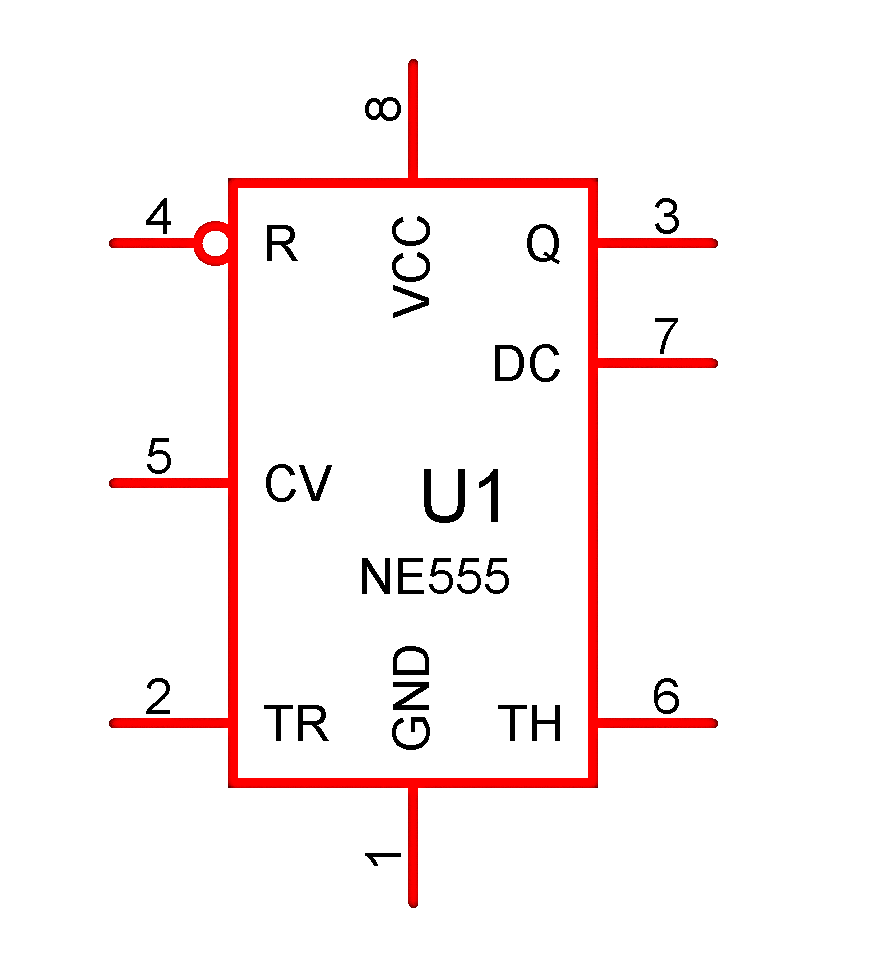
For a PWM motor speed control, PWM generator IC functions as its backbone. A typical single 555 timer IC (NE555) has 8 pins which collectively can be utilized as a PWM generator. Among those are GND, Trigger (TR), $V_{cc}$, Output (Q), Threshold (TH), and Discharge (DC). In Proteus – a professional circuit designing software, the NE555 IC (a name of 555 timer IC) shows the following pin configurations:
Since in this blog, we are mainly interested in implementing the 555 timer IC to generate a PWM signal, we rely on its pin configuration for the said task. If you’d like, you can read in-depth about the IC, its core components, and their functionality at this in-depth 555 time IC guide.
For this circuit implementation, you would need the following main parts:
| Part Name | Symbol in The Circuit | Quantity | Value |
| DC Power | Battery | 1 | 12V |
| Diode | $D_{1}$-$D_{3}$ (1N5408) | 3 | – |
| Resistor | $R_{1}$, $R_{3}$ | 1, 1 | 4.7kΩ, 100Ω |
| Potentiometer | $RV_{1}$ | 1 | 100kΩ |
| Capacitors | $C_{1}$-$C_{2}$, $C_{3}$ | 2, 1 | 0.01µF, 0.1µF |
| Timer IC | U1-NE555 | 1 | – |
| MOSFET | Q1-IRFZ44N | 1 | – |
| DC Motor | – | 1 | 12V |
555 Timer Motor Controller Pin Configuration & Modes
The 555 timer IC has 3 modes on which it functions: i. Monostable ii. Bistable, and iii. Astable. In our case where the PWM wave is required without external trigger, we need to utilize the Astable mode of the IC. In Astable mode the pin configuration is described below:
| Pin Number | Description |
| 1: $GND$ | Ground for reference voltage (0V) |
| 2: $TR$ | Check V against 1/3 $V_{cc}$; triggers output high if lower than 1/3$V_{cc}$ |
| 3: $Q$ | PWM Output to MOSFET |
| 4: $R$ | Reset pin, connect with Vcc to power the chip, or to GND to stop |
| 5: $CV$ | Control pin, connect with GND with small cap. in series |
| 6: $TH$ | Compares voltage to 2/3$V_{cc}$; resets output when high. |
| 7: $DC$ | Auto-connect to GND in discharge phase |
| 8: $V_{cc}$ | Supply voltage |
Calculating ${R}_1$, ${R}_2$ and ${C}$ for Frequency ($f$) & Duty Cycle ($D$) For DC Motor Speed Controller
In Astable mode, resistors ( ${R}_1$ (Charging resistor), ${R}_2$ ) (Discharging resistor), and Timing Capacitor ($C$) fix the frequency f and Duty Cycle D. To calculate the frequency, and Duty Cycle respectively, we use the following formulas:
$$f=\frac{1}{t_{high}+t_{low}}$$
And
$$D = \frac{t_{high}}{t_{high} + t_{low}}$$
Adjusting Duty Cycle with Potentiometer
In the previous section, fixed value of ${R}_2$ was used which will give us fixed duty cycle. However, in our case we need to vary the duty cycle to control the DC motor speed. Therefore, replacing the ${R}_2$ with a potentiometer will solve our problem. For our case we are choosing 100kΩ potentiometer ${RV}_1$. A sample snippet of this part of the circuit is given below:
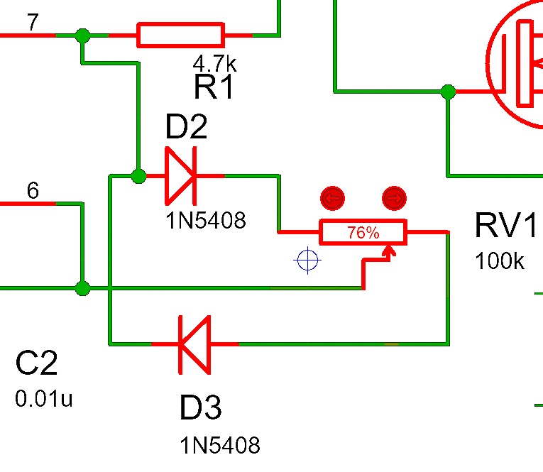
Since we want to keep the frequency constant and drive the motor using a variable duty cycle, we also need to add two steering diodes ($D_{2}$ and $D_{3}$) across the potentiometer ${RV}_1$. These diodes help direct current through different halves of the potentiometer (pot) during charge and discharge cycles.
During charging: Current flows through the fixed resistor $R_{1}$ plus the portion of the pot corresponding to the wiper position. In this wiring, higher pot positions increase the charging resistance ($R_{upper}$), resulting in higher duty cycle.
During discharging: Current flows through the remaining resistance ($R_{lower}$). As you turn the potentiometer toward the top end, the duty cycle increases smoothly from about 9% to 95%.
Sometimes, hobbyists need to settle for lower or higher value capacitors since they might not find the calculated capacitor in inventory. There is a whole range of capacitors of various sizes, capcitance, and voltages available on our inventory you can choose form. specThe frequency remains constant since the total resistance is always $R_{1}$ plus the full pot value ($RV_{1}$). So, the fPWM doesn’t drift when adjusting the pot—only the duty cycle changes.
Duty Cycle at Various Pot Values
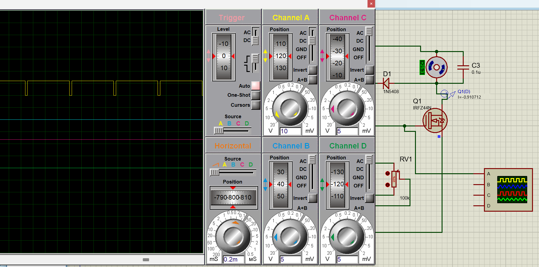
As you can see in the circuit diagram, we have attached an oscilloscope to check the output of the pin 3 going into the MOSFET. At this stage, it is appropriate to showcase the Duty Cycle waveform generated by the 555 timer IC when the pot value is:
- at 5%
- 25%
- 50%
- 75%, and
- 95%.
In all cases, the Time period ($T$) remains almost the same since it is set by the values of $R_{1}$, $RV_{1}$ (pot), and $C$. However, the duty cycle, that we need to vary using potentiometer, varies based on the following formulae:
$$t_{high}=0.693(R_1+R_{lower})C \quad ; \quad t_{low} = 0.693 \times R_2 \times C$$
$$R_{upper} = (1 – p)\times R_{pot} \quad ; \quad R_{lower} = p\times R_{pot}$$
Using the formulas above, let’s calculate the duty cycle for a pot value to demonstrate the expected results.
For 5% pot, the $p$ value is then 0.05, $R_{1}=4.7kΩ$ , $R_{pot}=100kΩ$, $C=0.01µF$
$R_{upper} = (1 – p)\times R_{pot} = (1-0.05)100kΩ \quad;\quad \boxed{R_{upper} = 95kΩ}$
$R_{lower}=p\times R_{pot} = 0.05\times100kΩ \quad;\quad \boxed{R_{lower}=5kΩ}$
$t_{high}=0.693(R_1+R_{lower})C = 0.693(4.7kΩ+5kΩ) 0.01 μF \quad ; \quad \boxed {t_{high}= 67.2\mu s}$
$t_{low} = 0.693 \times R_2 \times C = 0.693\times 95kΩ \times 0.01μF \quad ; \quad \boxed {t_{low} = 658\mu s}$
${T=t}_{high}+t_{low} = 67.2\mu s\ +\ 658\mu s \quad ; \quad \boxed {T=725\mu s} $
\( \displaystyle D = \frac{t_{high}}{T} \times 100 = \frac{67.2\,\mu s}{725\,\mu s} \times 100 \approx \boxed{D = 9.2\%} \)
This Duty Cycle can be visually confirmed by reviewing the simulation results demonstrated in the images below. Likewise, this Duty Cycle will also tell us about the expected speeds of the DC motor at specified pot values. For example, at 5% pot value, we should expect slower speeds, whereas at above 90% pot value, we should expect around maximum DC motor speed at no-load conditions.
The rest of the simulation results are given below:
Simulation Results of PWM for DC Motor Speed Controller Circuit
- Potentiometer at 5%

- Potentiometer at 25%
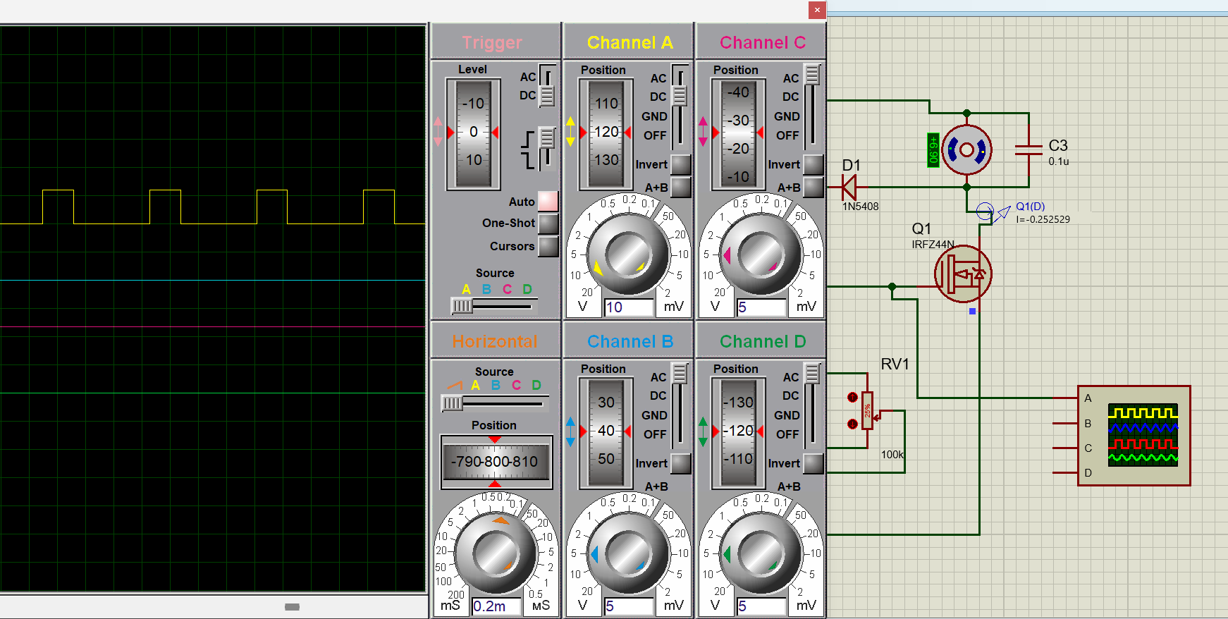
- Potentiometer at 50%
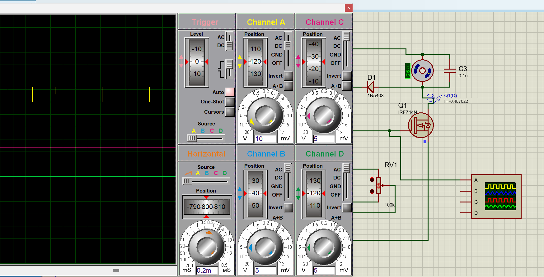
- Potentiometer at 75%

- Potentiometer at 95%
MOSFET PWM Motor Driver & Power Stage
The MOSFETs are power transistors that actually connect and disconnect the motor from the battery efficiently. The waveform generated at the output of pin 3 of the 555 timer IC, is provided to the MOSFET Gate through a 100Ω resistor. Upon receiving the HIGH signal (of the waveform generated earlier), the MOSFET connects the motor to battery, and at LOW condition, the MOSFET shuts off.
Choosing the Right MOSFET for DC Motor Speed Controller
Since MOSFET has the crucial role to play to drive the DC motor based on the signal received from the 555 timer IC, the MOSFET’s own capacity should be assessed and chosen carefully.
Some Typical considerations for the MOSFET for DC motor drive are given below:
- Voltage Rating: It should be >1.5 the motor voltage (e.g., 30V for 12V motors).
- Current Rating: Should be twice the motor stall current (e.g., IRFZ44N for 50A peak).
- Gate Charge: Low for fast switching (e.g., <60nC).
Correct MOSFET selection not only drives the motor smoothly, but its longer life span also ensures circuit longevity. Having a wide range of MOSFETS options such as in MOSFET kits, you can select the most appropriate MOSFET instead of settling for above or below the required ratings. You can choose a wide variety of MOSFET from this available MOSFET Kit.
Flyback Diode & Overvoltage Protection in DC Motor Speed Controller
We know that the PWM signal has fast HIGH/LOW switching to deliver precise power to the motor in dc motor speed controller. When the MOSFET shuts off, the motor’s inductance generates high voltage that has nowhere to go (typically it should go to ground via MOSFET’s drain to its source to ground). This summed up voltage appears as a high voltage spike with a potential to damage the MOSFET. Therefore, it is critical to protect the circuit with flyback diode.
A diode placed across DC motor terminals allows this collective voltage to go across the motor winding recursively, slowly dissipating this voltage using motor’s own internal resistance. Alternatively, you can also use TVS diode to safely dissipate the high voltage spike in high current DC motor operation conditions. You can read more in this guide about overvoltage protection using TVS diode.
DC Motor Speed Controller Schematic and Best Practices
For proteus simulation, the schematic for dc motor speed controller using PWM is given below:

From what is described in the article, two components in this circuit standout.
- A current probe added to the MOSFET drain connected to the motor’s negative terminal in series. This probe shows the value of current that the motor is drawing from the battery when MOSFET is in HIGH state.
- An Oscilloscope attached to pin 3 (Q) of 555 timer IC to observe the PWM pulse train in simulation for the PWM Duty Cycle validation.
To build this circuit, however, you must consider some best practices given below.
Component Placement
- The traces with high currents such as MOSFET, motor connections and $V_{cc}$ should be short in length, but with be wider to ensure proper power delivery without heating up the traces leading to circuit failure.
- Place the timing components group (which includes the potentiometer, steering diodes, resistors, and capacitors) close to the 555 timer IC. This will help avoid any stray noise or capacitance to misalign the required PWM generation.
- Keep the suppression parts such as flyback or TVS diode, and noise suppressing capacitors near the motor, close to their load point for swift action.
Testing and Optimization
In general the circuit design and simulation software such as Proteus, do not show the thermal issues such as temperature rising at the 555 timer IC or at the MOSFET. However, in practice the possibility and analysis of it is not only real, but crucial for circuit’s proper function and longevity to test the MOSFET, 555 timer IC, and motor’s negative line for temperature overshoot. If you feel the need, use appropriate heat sink(s) for MOSFET and NE555 timer IC.
Fine‑Tuning Duty Cycle Range for DC Motor Speed Controller
Although there can be tens of modifications that can be made to fine tune the dc motor speed controller, we’ll only discuss the most important ones in this article:
- Min/Max Duty: To power up the DC motor at even low Duty Cycle, add a 1kΩ resistor between the $TH-TR$ and pot wiper.
Add a parallel a resistor from $R_{1}$ to discharge pin to avoid 100% lock up. Effectively these resistors create baseline RC path that is always there to keep the cycle running in 100% charged or at min charging state. - Frequency Adjustment: Since humming frequency under the audible range can cause noise, adjust the $R_{1}$, and $C$ to drive the fPWM beyond audible range (>20kHz). This will not affect the duty range.
- Closed Loop Feedback for Real RPM Delivery: Although this circuit works pretty well in ideal conditions, the real-life circuits hardly face ideal conditions. For example, the provided duty cycle assumes the required RPM delivery. However, the load, friction, and torque may quite easily reduce the RPM despite required duty cycle provision. Remedy this issue in upgraded version of the circuit with implementation of hall sensor, and encoders with closed-loop feedback system that manages the Duty Cycle based on the real RPM of DC motor instead of assumed RPM.
Conclusion and Next Steps
You have now built a fixed-frequency PWM (Pulse Width Modulation) dc motor speed controller circuit with a NE555 timer IC, steering diodes, and a MOSFET. This setup ensures quiet operation, stable torque, and straightforward assembly.
For enhanced precision, consider integrating a rotary encoder or Hall effect sensor to provide closed-loop speed feedback as suggested earlier in this article. Alternatively, upgrading to a microcontroller-based system can offer advanced features and greater customization for your motor control needs. This approach will result in smooth, reliable, and efficient motor performance.