PMIC Selection Guide: Why Power Management ICs Are Critical
Why does this PMIC Selection Guide matter more than theoretical textbooks? Because real-world failures cost real money.
This comprehensive PMIC Selection Guide reveals the critical mistakes that have cost engineering teams millions in failed product launches. Last month, a Fortune 500 company recalled 50,000 IoT devices because of one preventable PMIC selection error—a $2.3 million mistake that this PMIC Selection Guide will help you avoid.
Remember when powering an MCU meant throwing a few linear regulators on your board? Those days are dead, and the stakes are higher than ever. This PMIC Selection Guide provides the systematic approach used by leading tech companies to navigate these challenges successfully.
The Problem with Discrete Solutions
Discrete regulators just can’t cut it anymore. You end up with boards covered in inductors, capacitors scattered everywhere, and power sequencing nightmares that make you question your career choices.
PMICs solve this chaos. Additionally, one chip handles multiple voltage rails, manages power sequencing, and optimizes efficiency across the entire load range. They also free up precious board space for the components that matter.

Core PMIC Architecture
The Critical Design Challenge
However, here’s the catch – PMICs aren’t just drop-in solutions. If you get the design wrong, you’ll face efficiency problems, thermal issues, or worse, intermittent failures that only show up after you’ve shipped 10,000 units. Therefore, this Power Management IC Selection Guide provides the systematic approach you need.
PMIC Selection Guide: How Power Management ICs Work
Core PMIC Architecture
Understanding PMIC fundamentals is essential for any effective Power Management IC Selection Guide. A PMIC is essentially multiple DC-DC converters, LDOs, and control logic crammed into one package. The magic happens in the control logic that coordinates everything.
The input stage handles the incoming voltage, usually 3.3V to 5V from your main supply. Meanwhile, the control block decides which regulators need to be active, manages power sequencing, and monitors system health. Subsequently, multiple regulators generate the different voltage rails your system needs.
Switching vs. Linear Regulation Integration
Most PMICs combine switching regulators for high-current rails like your processor core with LDOs for noise-sensitive analog circuits. Smart ones switch between pulse-skipping and continuous conduction modes based on load current.
Multi-Rail Power Generation Principles
The core voltage rail typically uses a buck converter topology. This makes sense since you’re usually stepping down from 3.3V or 5V to something like 1.8V or 1.2V for the processor core.
Bootstrap circuitry provides the gate drive voltages for the internal MOSFETs. Consequently, this eliminates the need for external charge pumps or isolated supplies that would eat board space and add complexity.
Cross-regulation happens when load changes on one rail affect other rails. However, good PMICs minimize this through independent feedback loops and compensation networks.
Dynamic Power Management Features
Here’s where PMICs get interesting. They adapt their behavior based on what your system is doing:
- Pulse-skipping at light loads: Skipping switching cycles when the output doesn’t need it
- Variable switching frequency: Higher frequency for transient response, lower for efficiency
- Adaptive dead-time optimization: Minimizing switching losses by tuning MOSFET timing
- Multi-phase operation: Using parallel converters to share load for heavy current demands

Multi-Rail Power Map: “Power Domains in MCU/MPU Systems
PMIC Selection Guide: Essential Parameters and Criteria
Efficiency Characteristics Analysis
Any thorough PMIC Selection Guide must address efficiency curves, which tell the whole story. A typical PMIC might hit 92% efficiency at 100mA load but drop to 70% at 1mA. That’s where quiescent current becomes critical.
Quiescent current specs range from 10µA to 50µA in standby mode. This sounds tiny, but for a battery-powered device that spends 99% of its time asleep, quiescent current determines battery life.
Load regulation accuracy runs ±1% to ±3% typically. However, tighter regulation costs more and burns more power, so match the spec to your actual requirements.
Dynamic Response Parameters
Real systems don’t have steady loads. For instance, take an ARM Cortex-A processor – it might sip 50mA while idling but suddenly jump to 800mA when decoding video. Your PMIC better respond fast enough to handle those spikes without letting the voltage sag.
Critical specifications include:
| Parameter | Specification | Impact |
|---|---|---|
| Transient response time | <50µs for 90% load steps | Prevents processor voltage droops |
| Output ripple | <20mV peak-to-peak | Analog circuit noise immunity |
| Input voltage range | 2.7V to 5.5V | Covers common supply rails |
| Output current capability | 500mA up to 3A per rail | Matches load requirements |
Control Interface Parameters
Nowadays, most PMICs talk I2C or SPI. Communication runs anywhere from 100kHz to 1MHz, which is plenty fast for adjusting power settings on the fly.
GPIO control lets you sequence power rails or switch operating modes. Additionally, response times matter when you’re trying to wake up from deep sleep in a hurry.
Fault reporting through interrupts can save your bacon. Furthermore, overcurrent, overtemperature, and undervoltage detection with programmable thresholds give you early warning before things go sideways.
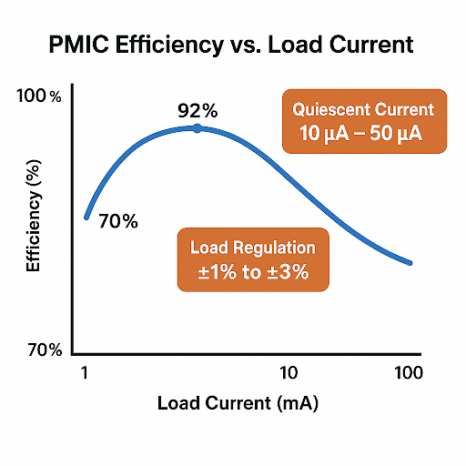
Efficiency Curve Chart: “Efficiency vs Load Current
PMIC Selection Guide by Application Type
PMIC Selection Criteria for Different Applications
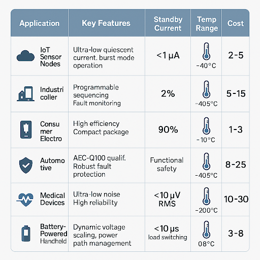
This PMIC Selection Guide matrix provides practical selection criteria for different applications:
| Application Type | Recommended PMIC Features | Key Specifications | Typical Cost Range |
|---|---|---|---|
| IoT Sensor Nodes | Ultra-low quiescent current, burst mode operation | <1µA standby, 85%+ efficiency at 1mA | $2-5 |
| Industrial Controllers | Programmable sequencing, fault monitoring, wide temperature range | ±2% regulation, -40°C to +125°C operation | $5-15 |
| Consumer Electronics | High efficiency, compact package, cost-optimized | 90%+ peak efficiency, QFN/WLCSP packaging | $1-3 |
| Automotive Systems | AEC-Q100 qualified, robust fault protection, extended temperature | Functional safety features, -40°C to +150°C | $8-25 |
| Medical Devices | Ultra-low noise, high reliability, backup power management | <10µV RMS noise, 20+ year MTBF | $10-30 |
| Battery-Powered Handhelds | Dynamic voltage scaling, power path management | Load switching <10µs, USB-C PD support | $3-8 |
Real-World Applications
Case Study: IoT Sensor Node Implementation
A wireless sensor node running on coin cell batteries for 10 years exemplifies why you need a comprehensive Power Management IC Selection Guide. Sounds impossible? Not with the right PMIC.
System Requirements Analysis
The system needs an ARM Cortex-M4 requiring dual rails at 1.8V for the core and 3.3V for peripherals. Additionally, the wireless module demands 3.3V at a 200mA peak during transmission. Meanwhile, sensors operate at 1.8V, drawing 10mA continuously and 50mA during measurement periods.
PMIC Solution Implementation
The PMIC solution uses a multi-output buck converter with integrated LDOs. Specifically, buck converters handle the high-current loads efficiently while LDOs provide clean power for the analog sensor interfaces.
Performance Results
The results speak for themselves—85% overall efficiency during active periods and 2µA standby current. That 2µA difference means the gap between 5-year and 15-year battery life.
Case Study: Industrial Controller with MPU
Industrial systems need reliability and precision. Multiple voltage domains, tight regulation, and bulletproof power sequencing are non-negotiable. The following PMIC Selection Guide examples demonstrate real-world implementation strategies.
System Architecture Requirements
The system specifications include an ARM Cortex-A series processor requiring 1.2V, 1.8V, and 3.3V rails. Furthermore, DDR memory power runs at 1.35V for LPDDR3 operation. Multiple peripheral power domains each have their own requirements.
Design Challenges
Design challenges emerge quickly. The processor needs 1.2V before 1.8V during startup. Additionally, DDR memory requires precise voltage levels within ±2%, or data corruption occurs. Peripheral domains need controlled shutdown sequences to prevent data loss.
Solution Implementation
The solution involves a programmable PMIC with configurable sequencing. Power-on delays are programmed through I2C configuration registers. Moreover, all rails are monitored continuously, and a graceful shutdown occurs if any fault occurs.
Case Study: Battery-Powered Medical Device
Medical devices can’t fail. Ever. Plus, they need 10+ years of battery life with no user maintenance.
Critical Requirements
Critical requirements include ultra-low quiescent current below 1µA, fault tolerance, and backup power management. Many PMICs claim low quiescent current but only measure the control circuitry, not the complete system.
Implementation Strategy
The implementation features power path management with automatic backup battery switching. If the primary battery voltage drops below the threshold, the system seamlessly switches to backup without a processor reset.
PMIC Selection Guide: Component Sourcing Strategy
Authorized Distribution Channels
For production quantities, this PMIC Selection Guide recommends sticking with authorized distributors.
Primary Sources
Primary sources include:
- Direct orders from semiconductor manufacturers for high-volume orders
- Major authorized distributors like Arrow, Avnet, Digi-Key, and Mouser
- Regional distributors for local market access and support
Advantages of Authorized Channels
The advantages justify the extra cost – genuine components, proper handling and storage, technical support, and warranty coverage. This beats dealing with counterfeit parts that fail in the field.
Online Component Marketplaces for Prototyping
Online marketplaces offer speed and flexibility for development and small quantities. Faster delivery, competitive pricing, and a wide selection of supporting components make them attractive for prototype builds.
E-commerce Platform Benefits
E-commerce platforms offer next-day delivery for common parts, small-quantity pricing for prototype builds, one-stop shopping for PMICs plus inductors, capacitors, and other passives, and easy comparison shopping across suppliers.
Quality Verification Practices
Quality verification practices matter. Therefore, look at supplier ratings and return policies before ordering. Avoid sellers with zero rating history or prices that make you wonder what’s wrong with the parts.
Sourcing Supporting Components
PMICs need quality supporting components to perform correctly. High-frequency inductors require low DCR and stable characteristics across temperature. Furthermore, low-ESR capacitors work best with ceramic caps for switching applications and tantalum for bulk storage. Precision resistors in feedback networks determine output voltage accuracy.
PCB Fabrication Considerations
PCB fabrication considerations include via stitching for thermal management, controlled impedance for high-speed signals, and adequate copper thickness for current carrying capacity.
Assembly services become critical since PMICs often come in QFN or BGA packages requiring precise pick-and-place equipment and controlled reflow profiles.
Lead Time and Inventory Management
Planning prevents problems. Standard parts typically need 2-4 week lead times while custom or programmed PMICs require 6-12 weeks. Buffer stock for critical components prevents production delays. Additionally, alternative part qualification gives you backup options when preferred parts become unavailable.
Supply Chain Risk Mitigation
Supply chain risk mitigation involves multi-sourcing strategies, component obsolescence tracking, and early warning systems for end-of-life announcements.
Cost Optimization Strategies
Volume pricing kicks in at predictable breakpoints around 100, 1K, and 10K quantities typically. Package options impact cost since QFN packages cost less than BGA but require more board space.
Programming costs for configurable PMICs add $0.10 to $0.50 per part, but external components worth more than that are eliminated.
Total cost analysis should include component cost, PCB area plus assembly complexity. Furthermore, a more expensive PMIC that eliminates external components often reduces total system cost.
Common Problems and Solutions
Efficiency Degradation Issues
Your PMIC hits 90% efficiency in simulation but only 75% on the bench. This frustrating problem usually comes from poor decoupling capacitor placement, which creates voltage drops, wrong inductor selection, where too much DCR kills efficiency, or switching frequency not optimized for your load profile.
Proven Solutions
Solutions start with placing input caps within 2mm of PMIC pins. Calculate the impact of inductor DCR using the formula Power loss = I²R. Additionally, choose the switching frequency based on efficiency versus component size trade-offs.
Power Sequencing Failures
System hangs during startup or behaves erratically during power down typically indicate sequencing problems. Map voltage dependencies since most processors need core voltage before I/O voltage. Moreover, memory controllers need multiple rails in a specific order.
Implementation Strategy
Program sequencing delays correctly using enable pins to control timing. Monitor power-good signals before enabling downstream rails to ensure proper startup.
Thermal Management Challenges
PMIC overheating in compact designs triggers thermal shutdown and system instability. You can calculate how much heat you’re generating with this simple formula: Power dissipation = (Vin-Vout) × Iout × (1-η).
Practical Example
Let’s say you’re converting 3.3V down to 1.8V at 500mA with 85% efficiency. Power loss = (3.3-1.8) × 0.5 × (1-0.85) = 0.11W. Not terrible, but it adds up.
Thermal Solutions
Fix it by optimizing your thermal pad design with plenty of via stitching. Furthermore, multi-phase converters spread the heat around, and smart thermal throttling turns off the power when things get toasty.
EMI/EMC Compliance Issues
Switching noise from PMICs interferes with sensitive analog circuits or fails radiated emissions testing. Proper ground plane design with minimal slot cuts helps. Additionally, implementing an EMI filter at PMIC input reduces conducted noise. Spread spectrum switching distributes noise energy across frequency ranges.
Component Sourcing and Quality Issues
Counterfeit or substandard components cause field failures months after shipping. Visual inspection for package markings, electrical testing of key parameters, and supplier qualification processes help catch problems early.
Prevent these problems by working closely with authorized distributors, keeping good records of where your components came from, and setting up incoming inspection procedures that catch problems before they make it to production.
PMIC Selection by Application
Choosing a PMIC: Frequently Asked Questions
Design and Implementation
Q: How do I calculate my MCU system’s required output current for each PMIC rail?
A: This PMIC Selection Guide recommends adding up all loads on each rail, including MCU core current, peripheral current, and any external components. Add 20-30% margin for transients and component tolerance. Check MCU datasheets for dynamic current specifications during different operating modes.
Q: What’s the difference between a PMIC and multiple discrete DC-DC converters?
A: PMICs integrate power management functions, sequencing logic, and fault protection in one package. Discrete converters give you more flexibility but require external sequencing circuits and take more board space. Furthermore, PMICs usually cost less in total system cost.
Q: How do I ensure proper power sequencing for my MPU application?
A: Check processor documentation for required power-on sequence. Most need core voltage before I/O voltage with specific timing requirements. Use PMIC programmable delays or enable pins to control sequence. Additionally, monitor power-good signals before enabling next rail.
Efficiency and Performance
Q: What causes PMIC efficiency to drop at light loads and how can I prevent it?
A: Switching losses and quiescent current dominate at light loads. Look for PMICs with pulse-skipping modes, variable switching frequency, or burst mode operation. Some PMICs automatically switch to LDO mode at very light loads.
Q: How do I select the right inductor value for my PMIC’s switching regulators?
A: Start with PMIC datasheet recommendations. Higher inductance reduces ripple current but slows transient response. Therefore, lower inductance improves transient response but increases ripple and core losses. Typical range spans 1µH to 10µH for most applications.
PCB Design and Layout
Q: What PCB layout guidelines are most critical for PMIC performance?
A: Keep switching current loops small, place input caps close to PMIC pins, use adequate via stitching for thermal management, minimize noise coupling to sensitive circuits, and maintain proper ground plane integrity.
Sourcing and Supply Chain
Q: Where can I source PMICs for small-scale prototyping versus large-scale production?
A: For prototyping, online distributors offer small quantities with fast shipping. For production, work with authorized distributors or directly with manufacturers for volume pricing and supply chain support.
Q: How do I verify the authenticity of PMICs from online suppliers?
A: Check package markings against manufacturer specifications, verify electrical parameters match datasheet values, use suppliers with good ratings and return policies, and avoid prices significantly below market rates.
Q: What are typical lead times for custom or programmable PMICs?
A: Standard parts need 2-4 weeks. Programmed parts require 6-12 weeks depending on manufacturer and volume. Custom silicon takes 6+ months. Therefore, plan accordingly and maintain buffer inventory for critical projects.
Advanced Applications
Q: How do I implement thermal protection in high-power PMIC applications?
A: Use PMICs with integrated thermal shutdown, design adequate thermal vias and copper pours, consider active cooling for high-power applications, and implement software thermal monitoring with graceful degradation strategies.
Q: What are the key considerations for battery-powered PMIC designs?
A: Focus on ultra-low quiescent current, efficient power path management, and backup power switching. This comprehensive Power Management IC Selection Guide emphasizes that battery life depends heavily on standby current optimization.
PMIC Selection Guide: Final Recommendations
This Power Management IC Selection Guide provides the systematic approach needed to navigate the complexity of modern embedded power management. Whether you’re designing IoT sensor nodes, industrial controllers, or medical devices, the principles and selection criteria outlined here will help you choose the optimal PMIC solution.
Remember that successful PMIC implementation requires attention to both device selection and system-level design considerations. From efficiency optimization to thermal management, every aspect contributes to reliable, efficient operation in your target application.
References
- ARM Technical Reference Manual. (2024). “Processor Power Requirements and Management.”
- JEDEC Standards. (2023). “Memory Power Specifications and Interface Requirements.”
- Texas Instruments. (2024). “PMIC Application Notes and Design Guidelines.”
- Analog Devices. (2024). “Power Management Design Tools and Calculation Methods.”