In embedded systems, serial communication protocols like SPI and I2C connect microcontrollers to sensors, displays, memory chips, and other peripherals. Both are common, which is why the SPI vs I2C question comes up in almost every project.
SPI is widely used for high-speed devices such as TFT displays, flash memory, and fast ADC/DAC modules.
I2C, with its simple two-wire design and built-in addressing, is popular for lower-speed peripherals like sensors, EEPROMs, and RTCs.
Since these use cases overlap, many developers hesitate when comparing i2c vs spi for a new design.
The real challenge is that most beginners choose a protocol based only on speed or pin count. This often leads to problems later like unstable communication, extra wiring, higher power draw, or limited scalability.
What’s missing is a clear, practical way to understand spi versus i2c beyond the basic specs.
This article fills that gap. We’ll talk about the SPI vs I2C comparison in depth. We will break down the real design factors that matter: wiring complexity, throughput, power, noise, and how each protocol scales.
By the end, you’ll know exactly when to choose SPI and when I2C is the better fit for your application.
The I2C protocol is a simple two-wire serial communication interface originally developed by Philips (now NXP) for communication between chips on the same board.
It uses just two shared lines: SDA for data and SCL for the clock. With two wires connecting every device, the I2C interface is very friendly when it comes to wiring and pin usage.
Communication is synchronous and half-duplex which means devices take turns sending data on the bus.
I2C communication is synchronous and half-duplex. Synchronous means all devices share a clock signal (SCL), so timing is coordinated.
Half-duplex means data flows in only one direction at a time. Either the master sends data or a slave responds.
I2C uses an open-drain bus design, where devices can pull the line low but cannot drive it high.
Pull-up resistors keep the lines at a logic HIGH when idle. This allows many devices to safely share the same two wires, but it also means bus behavior depends on electrical loading.
As more devices or longer traces are added, signal rise times slow down, which can limit speed and reliability. That’s why I2C works best over short, board-level connections.
Each device on the bus has a 7-bit or 10-bit address, sent by the master at the start of every transfer.
Because addressing is built in, I2C does not need separate chip-select lines.
I2C is perfect for sensor clusters and modular designs because it allows devices to be added to SDA and SCL, without conflicting addresses.
Although I2C supports several speed modes, real-world throughput is lower due to protocol overhead like start/stop conditions and ACK/NACK signals.
In practice, I2C is best suited for low-to-moderate data-rate devices such as sensors, RTCs, EEPROMs, and GPIO expanders. Its main strengths are simplicity, scalability, and efficient pin usage.
What Is SPI? (Serial Peripheral Interface)
The SPI protocol is a high-speed synchronous serial communication interface originally introduced by Motorola.
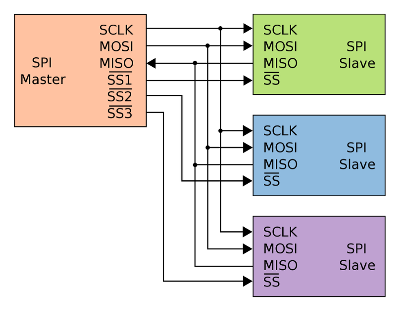
A typical SPI interface uses four signals: MOSI, MISO, SCLK, and CS. The master controls the clock and selects one slave at a time by pulling its chip-select line low.
Slaves never arbitrate for the bus, which keeps SPI simple and predictable.
A key advantage of SPI is that it’s full-duplex. With separate data lines in each direction, the master can transmit and receive data at the same time.
Every SPI transfer is effectively an exchange, which helps reduce latency and makes SPI feel faster than half-duplex protocols like I2C.
SPI also has very little protocol overhead. There’s no addressing, no acknowledgments, and no fixed framing. Each device defines its own command structure.
This keeps throughput high but shifts responsibility to the application layer if error detection or validation is required.
Speed is one of SPI’s biggest strengths. There’s no fixed maximum clock rate.
Many SPI peripherals run at 10–50 MHz or higher. Because SPI uses push-pull drivers, signals switch quickly, but that also means routing quality matters.
SPI works best over short distances on a single circuit board. When traces get long or when cables are used, the fast signal edges can cause problems like ringing or data errors.
For reliable communication, SPI connections are usually kept short and well routed.
SPI can talk to multiple peripherals, but each one normally needs its own chip-select (CS) line. This means that as you add more devices, you also need more control pins and more routing on the board.
To handle larger systems, designers may use extra hardware like decoders (which create multiple CS signals from fewer pins) or daisy-chain modes supported by some devices. These approaches work, but they add complexity.
SPI vs I2C: Key Differences
Now that we know what each protocol does, let’s look at spi vs i2c in the way designers actually think: wiring, speed, power, scalability, noise, and how hard they are to use.
Wiring Complexity
I2C wins on wiring simplicity. The whole I2C bus uses just two shared lines: SDA and SCL. Every master and every slave connects to these same two wires, with pull-up resistors on each line.
Adding a new device involves connecting SDA, SCL, power, and ground, making sure the addresses don’t clash, and you’re done.
PCB routing stays simple and you only spend two microcontroller pins no matter whether you have 2 devices or 10.
The trade-off is that those two wires are a single shared resource. Only one transfer happens at a time, and if SDA or SCL gets stuck low, the whole I2C interface is effectively down.
SPI uses more copper. A basic SPI bus needs MOSI, MISO, SCLK and at least one CS line per slave. With three slaves, that’s 4 shared lines plus 3 chip-selects from the master.
Pin usage and routing effort grow with every new SPI device. You can reduce CS pin count with tricks like decoders, I/O expanders, or daisy-chaining, but all of those add design complexity.
Data Speed & Throughput
When people search for i2c vs spi speed, the short answer is: SPI is almost always faster.
I2C was designed for low-to-moderate speeds. Typical modes are:
100 kHz (Standard Mode)
400 kHz (Fast Mode)
1 MHz (Fast Mode Plus)
3.4 MHz (High-Speed Mode), sometimes 5 MHz (Ultra-Fast, write-only)
In real designs, most I2C buses run at 100 kHz or 400 kHz. Adding more devices or longer traces increases electrical loading, which slows signal edges and can cause errors.
Faster I2C modes exist, but they require careful PCB layout and compatible devices.
SPI has no fixed speed limit. The clock speed is set by the master and depends on the devices and PCB quality.
Speeds of 10–50 MHz are common, and on short, clean traces SPI can go even higher. This makes SPI much faster than I2C in practice.
I2C also has more protocol overhead. Every byte includes extra bits for addressing, acknowledgments, and start/stop signals, so not all clock cycles carry data.
SPI streams data continuously with almost no overhead. It is also full-duplex, sending and receiving at the same time, while I2C is half-duplex.
As a result, SPI is the better choice for large or continuous data transfers like displays, fast sensors, or memory access.
For small, infrequent data reads, I2C’s lower speed is usually more than enough.
Power Consumption
Power is less talked about in spi vs i2c comparison, but it matters in low-power designs.
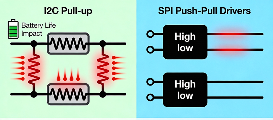
I2C uses pull-up resistors on SDA and SCL. Every time a device pulls a line low, current flows from VDD through the resistor to ground.
At higher speeds you often need smaller resistors for faster edges, which means higher current each time the line is low. That resistor current is pure loss.
SPI uses push-pull drivers, so lines are actively driven high and low. There are no pull-up resistors burning current when the line is low; static power is almost zero on the bus side.
Most of SPI’s power consumption comes from charging and discharging line capacitances at high frequency.
So which one wins?
For slow, occasional transfers, both draw very little and the difference is usually negligible.
For heavy or high-speed traffic, SPI tends to be more energy-efficient per bit, because it doesn’t constantly fight pull-up resistors.
Multi-Device Scalability
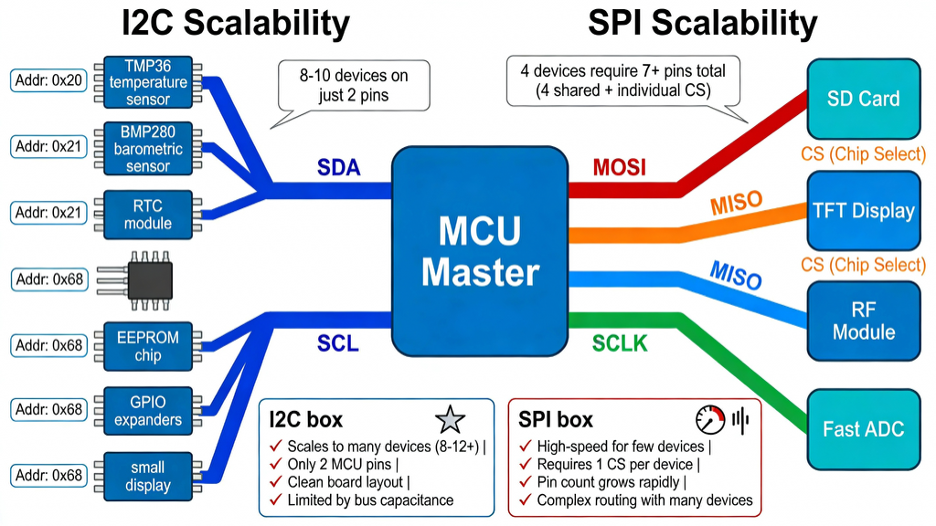
In terms of device count, I2C is designed to scale. You can have many slaves on one I2C bus, each with its own 7-bit or 10-bit address.
Adding a device doesn’t require new pins. You reuse the same SDA/SCL lines and make sure the address is unique.
Practical limits come from bus capacitance and the fact that some parts only offer a few address options, but wiring-wise it’s very clean.
SPI technically supports as many slaves as you like, but each one expects its own CS line. Microcontrollers only have so many GPIOs, and routing dozens of chip-select traces quickly becomes messy.
You can add decoders, CS expanders, or daisy-chain devices that support it, but every trick moves complexity into hardware or firmware.
Also, both spi vs i2c share the fact that only one device is active on the bus at a time, but SPI’s higher speed makes polling multiple devices faster in practice.
Noise Immunity & Cable Length
Neither I2C nor SPI is meant as a long-distance field bus, but they behave differently with noise and cable length.
I2C’s open-drain, pull-up design means the lines are relatively high impedance when idle. That makes them more sensitive to injected noise and to capacitive loading.
The official spec limits bus capacitance. Above that, edges get slow and the risk of glitches rises. The ACK/NACK mechanism helps detect some errors, but not all.
SPI uses strong push-pull drivers on separate lines, so logic levels are more robust and less likely to flip from small noise spikes.
However, SPI usually runs much faster, so signal integrity becomes the real challenge. At 10–20 MHz, a 30–50 cm cable already behaves like a transmission line.
Rough rule-of-thumb:
On a single board, with short traces, both I2C and SPI can be very reliable.
Over cables of ~0.5–1 m, I2C at 100 kHz or SPI at a few hundred kHz can work if you design carefully.
Beyond that, you usually slow down dramatically or convert to differential transceivers (RS-485, CAN, LVDS) instead of running raw I2C/SPI.
Protocol Complexity
Finally, let’s compare protocol complexity in this spi vs i2c comparison.
I2C packs a lot of cleverness into two wires. You have to handle:
Start and stop conditions
7-bit or 10-bit addressing
Read/write bits
ACK/NACK after every byte
Possible clock stretching
Optional multi-master arbitration
If you bit-bang i2c protocol in software, there are many edge cases. Even with a hardware I2C peripheral, you still deal with state machines, flags, and error conditions.
SPI is the opposite philosophy. The serial peripheral interface is basically: set clock polarity and phase (mode 0–3), choose a baud rate, pull CS low, shift bytes, pull CS high.
No addressing, no ACK, no start/stop, no built-in framing. That makes an SPI driver typically smaller and easier to write or bit-bang.
I2C pushes complexity into the bus protocol so you can do more with two pins.
SPI keeps the bus simple, but each device defines its own command format and you get no automatic error checking. With modern libraries, both feel easy from the application side: Wire.read() vs SPI.transfer().
But under the hood, I2C is doing more work to coordinate the shared bus, while SPI leans on the designer to get chip selects, modes, and integrity right.
When to Use I2C
Once you understand the basics of spi vs i2c, the real question is simple: which one should I use in my design?
The answer depends on pins, speed, distance, power, and how many peripherals you have to support. This section pulls everything together so you can make that call quickly.
When I2C Makes Sense
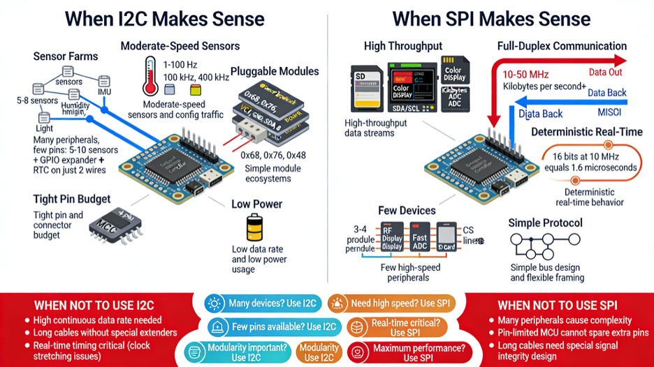
Use I2C when integration and pin efficiency matter more than raw speed:
Many peripherals, few pins
Classic i2c applications are “sensor farms.” If you have, say, 5–10 sensors, a GPIO expander, and an RTC, all sitting close to your MCU, I2C is ideal.
Two wires (SDA/SCL) can handle them all, instead of burning a chip-select line per device like SPI. On a tiny MCU, that’s a big win.
Moderate-speed sensors and config traffic
For readings in the 1–100 Hz range (temperature, pressure, IMU data, configuration registers, EEPROM reads), a 100 kHz or 400 kHz i2c interface is more than enough.
You’re moving small chunks of data occasionally, not streaming video.
Simple module ecosystems:
If you’re building a platform with pluggable boards or sensor hubs, using I2C keeps the pinout simple. Each module gets power, ground, SDA, SCL; the I2C address is its identity.
This is why so many breakout boards and “sensor hub” designs use I2C.
Tight pin or connector budget
When your connector only has room for 4 pins (VCC, GND, SDA, SCL), or your MCU is nearly out of GPIO, I2C is often the only practical option.
One small cable between boards can carry power plus the whole control bus.
Motion Sensing
A common real-world example of I2C in action is motion sensing. Devices like digital accelerometers and IMUs often use I2C because they produce relatively small amounts of data at regular intervals and benefit from simple wiring.
For instance, accelerometers such as the ADXL345 or multi-sensor IMUs like the MPU-9250 are frequently connected over I2C in robotics, wearables, and IoT systems.
When SPI Makes Sense
Use SPI when performance and timing dominate your decision:
High-throughput data streams
Classic spi applications are SD cards, external flash, high-speed ADC/DACs, and color displays.
If you’re moving kilobytes per second or more, SPI at 10–40 MHz (or higher) simply runs circles around I2C.
Full-duplex communication
If your device needs to send and receive at the same time (e.g., commands going out while data comes back every clock), SPI is the better tool.
The separate MOSI/MISO lines let you pipeline transfers in a way I2C can’t.
Few devices, point-to-point links
If you only have one or a couple of key peripherals (e.g., one radio module, one display, one external ADC), dedicating a few extra pins to SPI is worth it.
Wiring is still manageable and you get maximum performance.
Simple bus, flexible framing
If you prefer to control framing yourself and avoid the complexity of start/stop/ACK, SPI is appealing.
It’s just clock and shift registers; your driver code defines the command structure. In those situations, I2C (or another bus entirely) usually simplifies your life.
SPI is often chosen for data acquisition tasks where speed and timing consistency matter.
Analog-to-digital converters like the MCP3202 use SPI to deliver fast, predictable sampling with minimal protocol overhead.
How Real Microcontrollers Use I2C and SPI
It’s one thing to compare spi vs i2c on paper and another to see how real boards use them.
Across popular microcontrollers you’ll notice a pattern: I2C handles “many devices, low data,” while SPI handles “few devices, high data.”
Here are common examples you’ll see in actual projects.
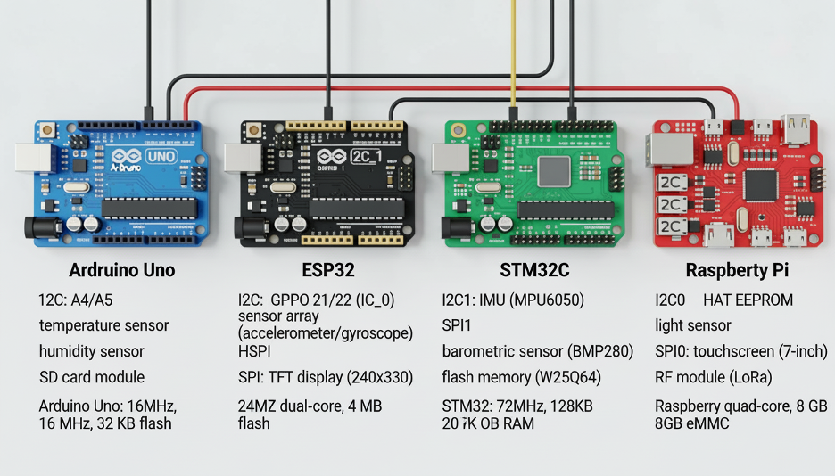
Arduino Uno
The Arduino Uno (ATmega328P) exposes I2C on A4 (SDA) and A5 (SCL).
Most beginners use these two pins to connect multiple I2C sensors or small displays because the wiring stays simple and the Wire library abstracts the protocol.
A typical setup might include an I2C OLED, a barometric sensor, and an RTC—all sharing the same two lines at 100–400 kHz.
SPI on the Uno (pins 10–13, also on the ICSP header) is reserved for the heavy lifting.
Modules like the Ethernet Shield or SD card reader rely on the spi interface at 4–8 MHz because they need much higher throughput.
You can easily run I2C sensors and an SPI SD card at the same time, and many Uno-based dataloggers do exactly that.
ESP32
The ESP32 brings more flexibility. It has multiple hardware I2C and SPI controllers, so IoT projects often combine several of each.
A typical ESP32 sensor hub might read temperature, humidity, pressure, and light sensors over I2C on just two pins.
SPI, meanwhile, handles high-bandwidth peripherals. Most ESP32 projects drive a TFT display over SPI at 20–40 MHz for smooth graphics.
The ESP32’s own program flash also uses Quad-SPI, showing how deeply SPI is baked into performance-critical parts of the system.
When building dataloggers, the ESP32 often writes to an SD card over SPI while reading sensors via I2C—both buses running independently.
STM32
STM32 MCUs usually include several I2C and SPI ports, and designers use them strategically.
Many IMU modules (gyro + accelerometer) sit on I2C, while faster sensors like barometric modules or external flash chips use SPI. In a drone controller, for example, the STM32 may retrieve orientation data over I2C but log data and drive a display over SPI at high speed.
STM32-based boards also appear inside larger systems.
The Raspberry Pi Sense HAT, for instance, uses I2C between the Pi and an onboard STM32, while that STM32 internally drives its LED matrix and sensors using SPI.
This mix reflects real engineering practice: I2C for lightweight control paths, SPI for bulk data.
Raspberry Pi
Although not a microcontroller, the Raspberry Pi exposes both buses on its GPIO header. Linux uses I2C by default to read HAT EEPROMs and to communicate with expansion sensors.
Makers frequently attach I2C sensors like the BME280 or small I2C OLED displays—it’s plug-and-play and libraries exist for almost every device.
SPI on the Pi is used for higher-speed modules: TFT touchscreens, RF transceivers (like the NRF24L01), or external ADC chips.
The Pi can stream SPI data fast enough to refresh displays or read multiple ADC channels in real time.
You can even set up an Arduino as an SPI slave for deterministic timing tasks while the Pi handles higher-level logic.
Final Thoughts
Choosing between spi versus i2c depends on your performance and wiring needs.
SPI gives you high speed, full-duplex transfers, and predictable timing, which is why it dominates in displays, memory cards, fast sensors, and anything that streams lots of data.
I2C brings simplicity, minimal wiring, and built-in addressing, making it perfect for sensor clusters, configuration chips, and low-to-moderate bandwidth tasks.
If you boil it down:
Use SPI when bandwidth or timing accuracy is critical.
Use I2C when you want to connect many devices cleanly with just two pins.
The easiest way to decide is to match the protocol to your constraints—how many peripherals you have, how fast they must talk, how long the wires are, and how many pins your MCU can spare.
Often the answer is obvious (“eight slow sensors → I2C” or “streaming graphics → SPI”). And in many real designs, the answer is “both”: I2C for configuration and sensing, SPI for logging or displays.
Understanding the trade-offs also helps you debug real issues. An unreliable I2C bus might simply be too long or too capacitive.
A noisy SPI signal might be the result of long jumpers or poor grounding. Recognizing the strengths and limitations of each bus saves hours of troubleshooting.
Modern embedded systems routinely mix I2C, SPI, and UART—each solves a different problem. A clean architecture uses the right interface in the right place.
At Flywing Tech, we support both ecosystems. Our I2C and SPI breakout boards, cables, connectors, and sensor modules make it easy to build reliable serial links without signal-integrity surprises.
Whether you’re wiring a cluster of I2C sensors or pushing high-speed data over SPI to a display or flash module, the right hardware makes all the difference.
FAQs: SPI vs I2C
Which is faster, SPI or I2C?
SPI is faster in almost every situation. I2C typically runs at 100 kHz to 1 MHz (up to 3.4 MHz in high-speed mode), while SPI can run at 10–50+ MHz on many microcontrollers.
SPI also has less protocol overhead and can send and receive at the same time, so its effective throughput is far higher.
Why does I2C need pull-up resistors?
I2C uses open-drain outputs, which means devices can only pull SDA/SCL low. Pull-up resistors hold the lines high when no device is driving them.
Without pull-ups, the bus would float and you’d never get a valid logic “1.” Pull-ups also allow multiple devices to share the same two lines safely.
Is SPI full-duplex?
Yes. SPI uses separate MOSI and MISO lines, so the master and slave can exchange data simultaneously on every clock cycle.
I2C is half-duplex, meaning it can only communicate in one direction at a time.
Does SPI support multiple slaves?
Yes. A single SPI master can talk to many slaves, but each slave needs its own chip-select (CS) line.
All devices share MOSI, MISO, and SCLK; the CS signal decides which one is active. Designs with many SPI devices often use decoders or expanders to manage CS lines.
When should I use SPI instead of I2C?
Use SPI when you need high speed, low latency, or full-duplex transfers. It’s the better choice for displays, SD cards, high-rate sensors, flash memory, radio modules, and anything that streams lots of data.
SPI is also a good fit when you only have one or two peripherals and pin count isn’t a concern.
Is I2C good for long cable lengths?
Not really. I2C is meant for short PCB-level communication. The bus capacitance limit (~400 pF) usually translates to under 1 meter of reliable wiring.
Long cables slow down edges, introduce noise, and cause corrupted data. For multi-meter links, use UART (with RS-485) or CAN instead.
Can I run SPI and I2C at the same time?
Yes. SPI and I2C use different pins and peripherals, so they work independently.
Many systems read sensors via I2C while streaming data to an SD card or display over SPI at the same time. As long as pins don’t overlap, both buses can operate concurrently.
Why does SPI need separate chip-select lines?
SPI has no addressing system. Every slave listens to MOSI and SCLK, so the master must use CS lines to select which device should respond.
When CS is high, a slave ignores the bus; when CS is low, it becomes active. This prevents multiple devices from driving MISO simultaneously.
Which protocol uses less power?
For low-speed, occasional communication, both use little power. At higher speeds, SPI is typically more power-efficient because it uses push-pull drivers (no resistor losses).
I2C burns energy every time SDA or SCL is pulled low. For large data bursts, SPI usually completes the transfer faster and with less wasted current.
Do Arduino and Raspberry Pi support both SPI and I2C?
Yes. Arduino boards expose both interfaces (Wire for I2C, SPI library for SPI), and you can use them together in one sketch.
Raspberry Pi also provides both on its GPIO header, letting you attach I2C sensors while driving displays or ADCs via SPI.
Most modern microcontrollers support both protocols because they serve different roles.