The LM7805 voltage regulator is one of the most widely used 5V linear regulator ICs in electronics. It converts a higher DC input, such as 9V or 12V, into a stable and regulated 5V output.
This makes it ideal for powering microcontrollers, sensors, logic circuits, and embedded systems. With just three pins and a few capacitors, you can build a reliable 5V power supply.
The LM7805 is also low noise, internally protected against thermal overload and short circuits, and widely available from multiple manufacturers.
However, because it is a linear voltage regulator, it dissipates excess voltage as heat. That means input voltage, load current, and thermal design must be considered carefully to avoid overheating.
In this guide, we’ll cover the LM7805 pinout, circuit design, datasheet specifications, dropout voltage, thermal calculations, capacitor selection, and when to use modern alternatives.
What Is the LM7805 Voltage Regulator?
The LM7805 voltage regulator is a fixed-output, positive linear voltage regulator IC designed to provide a stable 5V DC output from a higher DC input voltage.
It belongs to the well-known 78xx series, where “78” indicates a positive regulator and “05” represents the fixed 5V output.
In simple terms, the LM7805 acts as a voltage stabilizer. If your input supply fluctuates or carries ripple, the regulator maintains a steady 5V output as long as the input remains above the required dropout voltage.
Here are some core characteristics of LM7805 Voltage regulator:
- Fixed 5V output (no external resistor network required)
- Three-terminal design: Input, Ground, Output
- Typically supports up to 1A–1.5A output current (with proper heatsinking)
- Built-in protection features:
- Thermal shutdown
- Current limiting
- Safe operating area protection
LM7805 Key Electrical Specifications
When you search for the LM7805 datasheet, you’ll usually find a dense table of electrical parameters. But good design starts with understanding what those numbers actually mean for your circuit.
Below is a simplified, design-focused view of the most important LM7805 specifications, followed by practical interpretation.
| Parameter | Typical Value | What It Means in Practice |
| Output Voltage | 5V (±2% typical) | Output may vary slightly with temperature and load. Safe for most digital logic circuits. |
| Input Voltage Range | 7V – 35V | Must be above ~7V for regulation. Higher input increases heat dissipation. |
| Dropout Voltage | ~2V to 2.5V | Minimum difference required between input and output. |
| Maximum Output Current | 1A – 1.5A (thermal limited) | Achievable only with proper heatsinking. |
| Quiescent Current | ~5mA – 8mA | Small internal operating current; usually negligible in mains-powered designs. |
| PSRR (Ripple Rejection) | ~60 dB at 120 Hz | Good filtering of input ripple; suitable for low-noise applications. |
| Thermal Shutdown | ~150°C (junction) | Automatically turns off if overheated, but should not be relied upon for normal operation. |
1. Output Voltage (5V ± Tolerance)
The LM7805 is a fixed 5V regulator, meaning no external resistors are needed to set the output voltage. Under normal conditions, the output stays close to 5V within a small tolerance.
For microcontrollers and digital logic, this tolerance is more than acceptable. For precision analog circuits, factor in worst-case variation.
2. Input Voltage Range (7V–35V)
The minimum input voltage must exceed the output voltage by the dropout amount.
\[V_{IN(min)} \approx V_{OUT} + V_{Dropout}\]
For LM7805:
\[V_{IN(min)} \approx 5V + 2V = 7V\]
You can design for at least 7.5V to 8V input under worst-case load conditions. Avoid running right at the 7V threshold.
3. Dropout Voltage (~2V–2.5V)
Dropout voltage defines the minimum headroom required for regulation. If your supply drops below this limit:
- The output will begin to fall below 5V.
- Regulation is no longer guaranteed.
This is why LM7805 is not ideal for battery systems where voltage can sag significantly.
4. Maximum Output Current (Thermally Limited)
Although datasheets often mention 1A or 1.5A output capability, the real limitation is heat.
Power dissipation is:
\[P = (V_{IN} – V_{OUT}) \times I_{OUT}\]
\[P = (V_{IN} – 5) \times I_{OUT}\]
Example:
- 12V input
- 500mA load
\[P = (12 – 5) \times 0.5 = 3.5W \]
Without a heatsink, 3.5W is too much for a TO-220 package in still air.
5. PSRR (Power Supply Rejection Ratio)
The LM7805 offers good ripple rejection compared to switching regulators. This makes it suitable for:
- Sensor supply rails
- Audio circuits
- Analog measurement systems
However, PSRR decreases at higher frequencies, so switching noise still requires proper filtering.
LM7805 Pinout and Package Types
Understanding the LM7805 pinout is essential because many regulator failures are simply wiring mistakes.
Since the LM7805 voltage regulator is available in multiple packages, assuming all versions share the same pin order can damage both the IC and the load.
The most common version is the TO-220 package, widely used in through-hole designs, power supply modules, and DIY circuits.
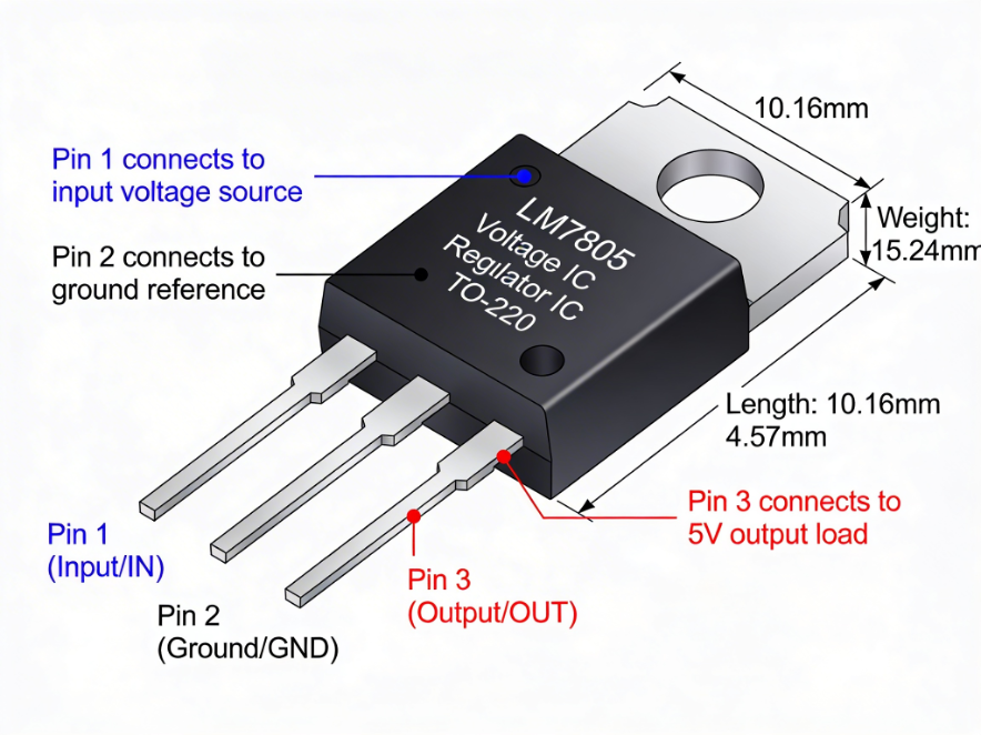
LM7805 Pin Configuration (TO-220)
Hold the IC with:
- The flat side (printed text) facing you
- The metal tab at the back
- The pins pointing downward
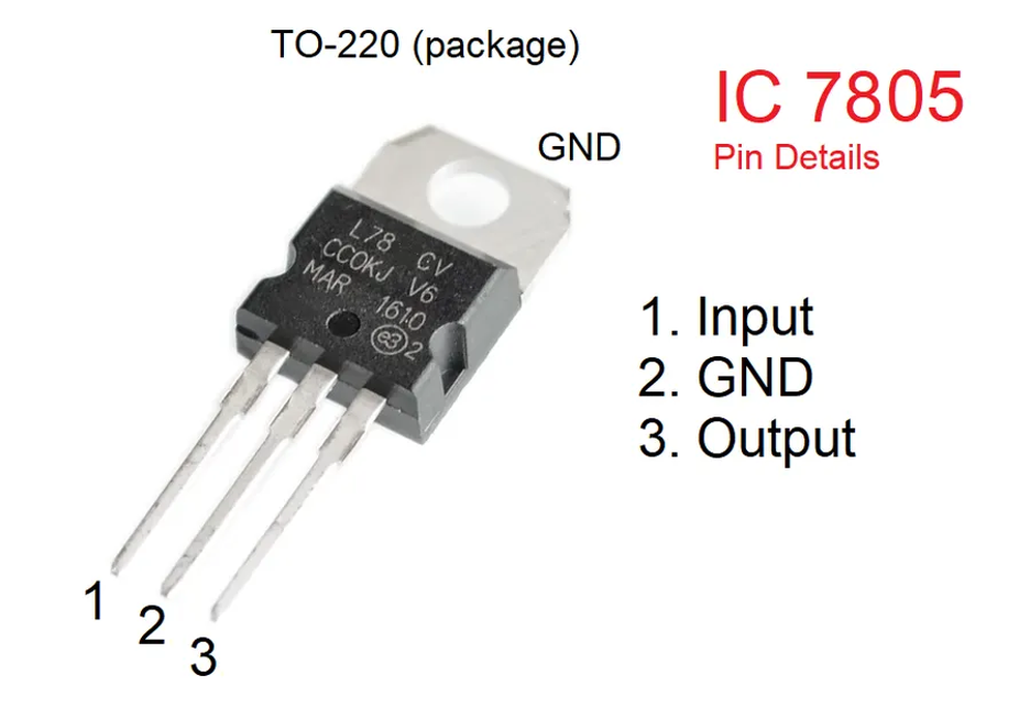
The pins from left to right are:
| Pin Number | Pin Name | Symbol | Description |
| 1 | Input | IN | Connects to unregulated DC supply |
| 2 | Ground | GND | Common reference for input and output |
| 3 | Output | OUT | Regulated 5V output |
A common mistake is assuming the left pin is output. It is not. Pin 1 is the input, and reversing input and output can immediately damage the regulator or downstream electronics.
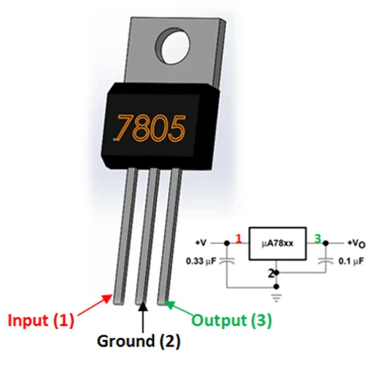
Input (IN)
Accepts DC voltage typically between 7V and 35V. It must exceed 5V by at least the dropout voltage (~2V). A 0.33µF capacitor should be placed close to this pin to prevent oscillation.
Ground (GND)
Serves as the reference for the internal control circuitry. The stability of this ground directly affects output accuracy. Poor grounding can introduce ripple or regulation error.
Output (OUT)
Provides the regulated 5V output. A 0.1µF ceramic capacitor should be placed close to this pin to improve transient response and prevent instability.
Pinout Differences Across Packages
Not all LM7805 packages use the same pin order. This is a frequent source of wiring errors.
| Package | Pin 1 | Pin 2 | Pin 3 | Notes |
| TO-220 | IN | GND | OUT | Most common version |
| TO-92 | OUT | GND | IN | Often reversed compared to TO-220 |
| SOT-223 | GND | OUT | IN | Always verify datasheet |
| D2PAK | IN | GND | OUT | Tab typically connected to GND |
The TO-92 package is commonly reversed compared to TO-220. Always confirm the exact manufacturer’s datasheet before wiring.
How the LM7805 Works
To design properly with the LM7805 voltage regulator, it helps to understand what is happening inside the IC. Even though it only has three pins, the internal structure is more sophisticated than it looks.
At its core, the LM7805 is a linear series regulator. It continuously adjusts an internal pass transistor to maintain a steady 5V output, even when input voltage or load current changes.
Inside the LM7805, you’ll find three main functional blocks:
| Block | Function | Why It Matters |
| Reference Voltage | Provides a stable internal reference (band-gap reference) | Ensures output remains precisely 5V |
| Error Amplifier | Compares output voltage to reference | Adjusts regulation in real time |
| Series Pass Transistor | Controls current flow from input to output | Drops excess voltage as heat |
- The internal reference voltage generates a stable baseline.
- The error amplifier compares the actual output voltage to the internal reference.
- If the output drops (for example, when load increases), the amplifier increases conduction through the pass transistor.
- If the output rises, the amplifier reduces conduction.
- This feedback loop operates continuously and very quickly.
This closed-loop system is what keeps the output stable at 5V.
Linear Regulation vs Switching Regulation
Understanding this internal behavior explains the efficiency limitation.
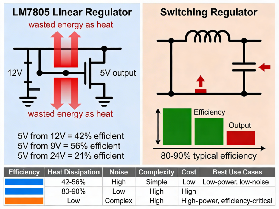
For linear regulators:
\[ η≈VINVOUT×100% \]
So:
- 5V from 12V → ~42% efficient
- 5V from 9V → ~56% efficient
- 5V from 24V → ~21% efficient
The remaining energy becomes heat. Switching regulators, on the other hand, use high-frequency switching and inductors to achieve efficiencies above 80–90%, but they introduce more complexity and electrical noise.
Built-In Protection Mechanisms
The LM7805 includes several internal safety features:
- Thermal shutdown (typically around 150°C junction temperature)
- Current limiting
- Safe operating area protection
These protections prevent catastrophic failure but should not be relied upon as normal operating conditions. If thermal shutdown activates frequently, the design needs improvement.
During testing, if output voltage deviates significantly from specification, verify that the regulator is genuine and within tolerance.
Using verified components such as the Fairchild / ON Semiconductor LM7805 helps eliminate uncertainty caused by counterfeit or recycled parts.
LM7805 Circuit Diagram and Component Selection
Once you understand how the LM7805 works internally, the next step is designing the LM7805 circuit correctly. While the regulator only has three pins, proper capacitor selection and placement are essential for stable operation.
Many failures attributed to the LM7805 are actually caused by missing or poorly placed capacitors. A standard LM7805 circuit includes:
- Unregulated DC input
- Input bypass capacitor
- Output bypass capacitor
- Common ground reference
The basic connection is:
- Pin 1 (IN) → DC input voltage
- Pin 2 (GND) → Ground
- Pin 3 (OUT) → Regulated 5V output
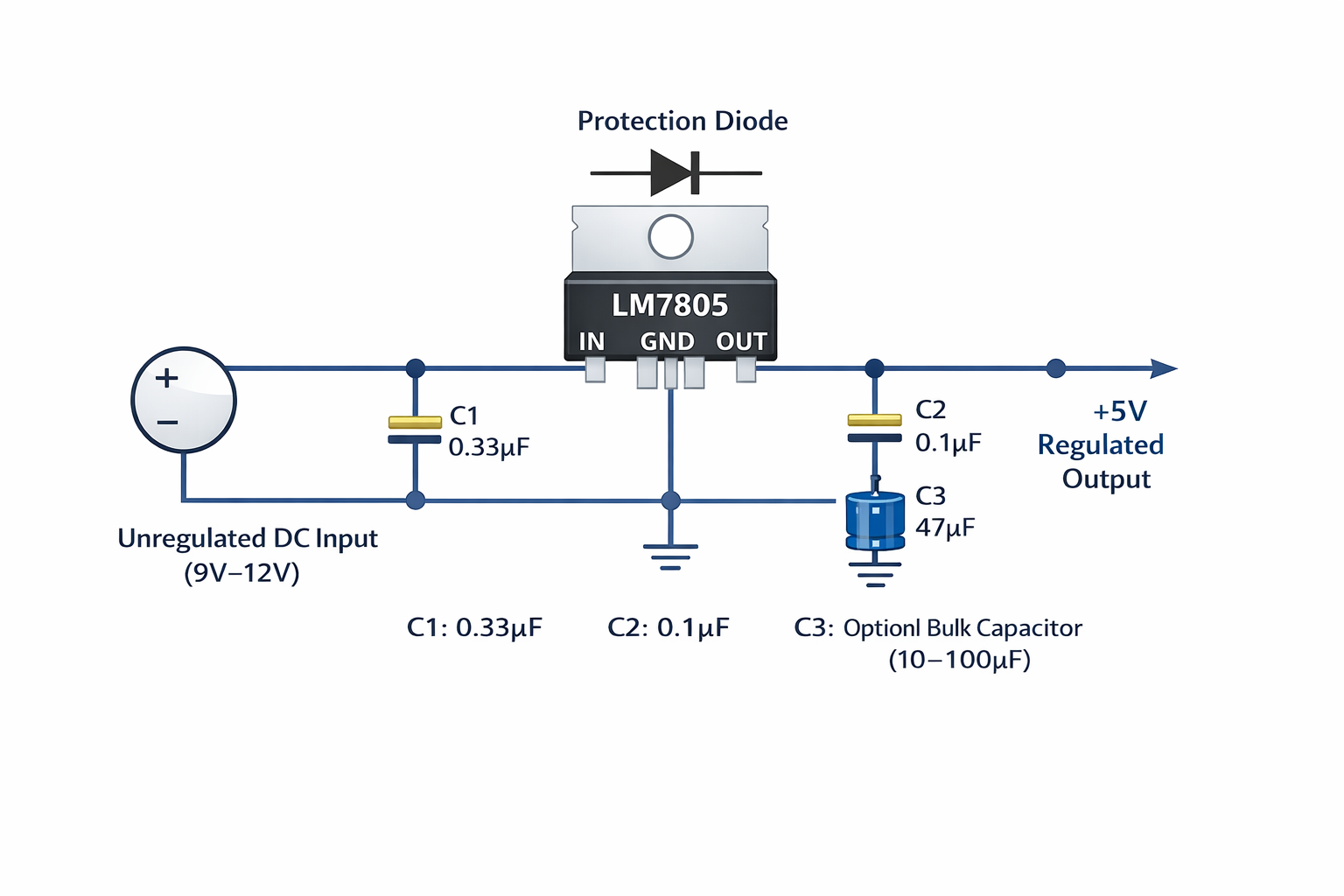
Capacitors are connected between input-to-ground and output-to-ground. Although the LM7805 can sometimes function without capacitors in ideal lab conditions, datasheets and real-world experience strongly recommend them.
| Component | Typical Value | Purpose |
| Input Capacitor (C1) | 0.33µF ceramic | Prevents oscillation and stabilizes input |
| Output Capacitor (C2) | 0.1µF ceramic | Improves transient response |
| Optional Bulk Capacitor (C3) | 10µF–100µF electrolytic | Handles load spikes and ripple |
Input Capacitor (0.33µF)
If the power source is physically far from the regulator or has high impedance, the input capacitor prevents high-frequency oscillation.
Output Capacitor (0.1µF)
When load current changes suddenly (for example, a microcontroller switching states), this capacitor supplies instantaneous current until the internal control loop adjusts.
Bulk Output Capacitor (10–100µF)
Not always mandatory, but strongly recommended when:
- Load changes rapidly
- Power traces are long
- Current draw exceeds a few hundred milliamps
Capacitor Placement Rule (Critical for Stability)
Placement matters more than value in many cases.
- Place the 0.33µF input capacitor as close as possible to Pin 1.
- Place the 0.1µF output capacitor directly next to Pin 3.
- Keep leads short to minimize inductance.
Long wires or breadboard layouts can introduce unwanted inductance, causing oscillation or unstable output.
Protection Diode
In some circuits, especially when large output capacitors are used, it is wise to add a diode from output to input (anode at output, cathode at input).
This prevents reverse discharge through the regulator if:
- Input voltage collapses suddenly
- Output capacitor remains charged
It protects the internal structure of the LM7805.
LM7805 Thermal Design and Heatsink Calculation
Thermal design is the most important part of any LM7805 voltage regulator circuit. Because it is a linear regulator, all excess voltage is converted directly into heat.
If you ignore this, the regulator will enter thermal shutdown or operate unreliably.
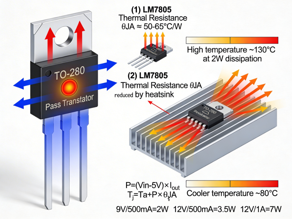
Step 1: Calculate Power Dissipation
\[P=(VIN−5)×IOUT\]
This equation tells you how much heat the LM7805 must dissipate.
| Input Voltage | Output Current | Power Dissipated |
| 9V | 500mA | 2W |
| 12V | 500mA | 3.5W |
| 12V | 1A | 7W |
| 24V | 200mA | 3.8W |
| 24V | 500mA | 9.5W |
As input voltage increases, dissipation rises quickly. This is why using LM7805 directly from 24V is often impractical at moderate current.
Step 2: Estimate Junction Temperature
Without a heatsink:
\[T_j = T_a + P \times \theta_{JA}\]
Where:
- Ta = ambient temperature
- θJA ≈ 50–65°C/W for TO-220 without heatsink
Example (No Heatsink)
- Vin = 12V
- Iout = 300mA
- P = 2.1W
- Ta = 25°C
\[T_j = 25 + (2.1 \times 50) = 130^\circ C\]
This is close to thermal shutdown (~150°C). Even 300mA can require a heatsink depending on airflow.
Step 3: Heatsink Requirement
With a heatsink:
\[T_j = T_a + P \times (\theta_{JC} + \theta_{CS} + \theta_{SA})\]
To select a heatsink:
\[\theta_{SA(max)} = \frac{T_{j(max)} – T_a}{P} – \theta_{JC} – \theta_{CS}\]
This gives the maximum thermal resistance your heatsink can have.
When working near the upper current limit, using a high-quality TO-220 package regulator improves thermal stability. Industrial-grade options like the LM7805ECT variant are commonly selected for improved consistency under elevated temperatures.
Applications of the LM7805 Voltage Regulator
The LM7805 voltage regulator remains popular because it solves a very specific and common problem: generating a stable 5V rail from a higher DC source.
While modern switching regulators dominate high-efficiency systems, the LM7805 still performs well in simple, low-to-moderate current applications.
Below are the most practical and common use cases.
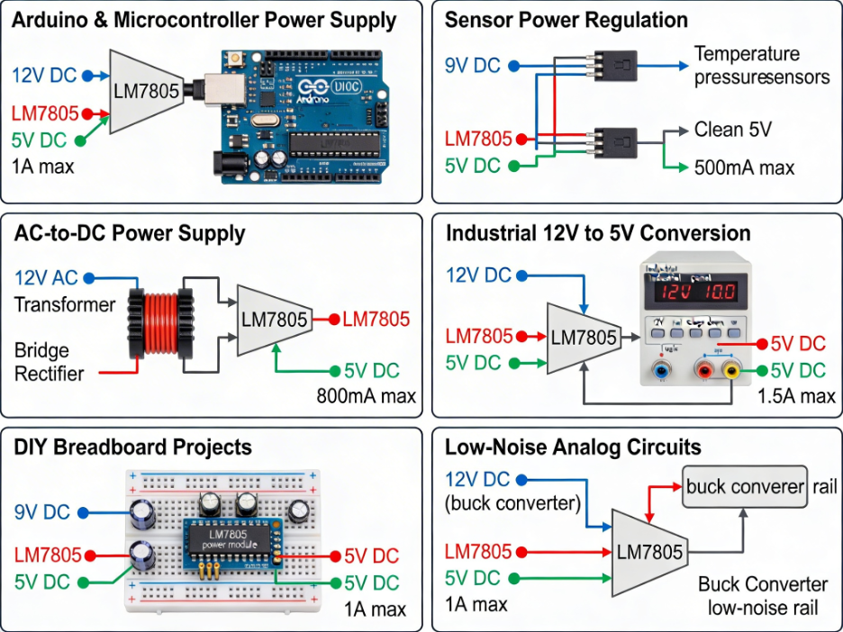
1. Arduino and Microcontroller Power Supply
One of the most frequent uses of the LM7805 is powering:
- Arduino boards
- AVR and PIC microcontrollers
- Development boards
- Digital logic circuits
If you have a 9V or 12V adapter and need a regulated 5V rail, the LM7805 provides a straightforward solution.
For custom embedded boards, the LM7805 is often placed before a 5V logic rail feeding the MCU and peripherals.
2. Sensor Power Regulation
Many sensors require clean and stable 5V. Because the LM7805 is a linear regulator, it produces:
- Low ripple
- Low switching noise
- Stable DC output
This makes it suitable for:
- Temperature sensors
- Pressure sensors
- Analog measurement systems
- Basic audio circuits
In precision systems, designers sometimes use a buck converter first (for efficiency) and then an LM7805 as a final low-noise stage.
3. AC-to-DC 5V Power Supply
A classic application uses:
- Transformer
- Bridge rectifier
- Bulk filter capacitor
- LM7805 regulator
This design converts AC mains to regulated 5V DC. It is commonly used in:
- Educational labs
- DIY power supplies
- Low-power control circuits
4. Industrial 12V to 5V Conversion (Low Current)
In industrial control panels, 12V rails are common. The LM7805 can step down 12V to 5V for:
- Logic boards
- Relay drivers
- Interface circuits
However, at moderate current levels, heatsinking becomes necessary.
If current demand exceeds a few hundred milliamps continuously, a buck converter is usually more efficient.
5. DIY Bench Supply and Breadboard Projects
The LM7805 is widely used in:
- Breadboard power modules
- Prototyping boards
- Educational kits
Its simplicity makes it ideal for learning voltage regulation principles.
6. Low-Noise Analog Rails
Switching regulators can introduce high-frequency noise. In mixed-signal systems, designers sometimes use:
- Buck converter → intermediate voltage
- LM7805 → final clean 5V rail
This approach balances efficiency and noise performance.
How to Test and Validate an LM7805 Circuit
After building an LM7805 voltage regulator circuit, testing is essential before connecting sensitive electronics.
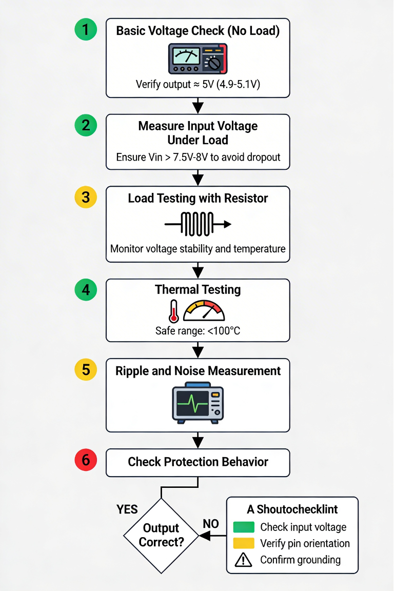
Step 1: Basic Voltage Check (No Load)
Before connecting your actual circuit:
- Power the LM7805 with the intended input voltage.
- Measure the output with a multimeter.
- Confirm it reads close to 5V (typically 4.9V–5.1V).
If the output is significantly lower:
- Check input voltage.
- Verify pin orientation.
- Confirm proper grounding.
Step 2: Measure Input Voltage Under Load
Many issues occur because input voltage drops when load current increases. With your load connected:
- Measure Vin directly at the regulator input.
- Ensure Vin remains above 7.5V–8V to avoid dropout.
If Vin sags, the supply or wiring may be insufficient.
Step 3: Load Testing
Use a known resistive load to simulate current draw.
Example:
- For 500mA load at 5V:
\[R = \frac{V}{I}\]
\[R = \frac{5}{I_{LOAD}}\]
\[R = \frac{5}{0.5} = 10\Omega\]
Connect the resistor and monitor:
- Output voltage stability
- Regulator temperature
- Any voltage drop under sustained load
This confirms whether the LM7805 can handle the intended current.
Step 4: Thermal Testing
Touch testing is crude but useful:
- If the regulator is too hot to touch within seconds, thermal design is insufficient.
For better evaluation:
- Use an infrared thermometer.
- Estimate junction temperature using dissipation calculations.
If the device approaches unsafe temperatures:
- Add heatsink.
- Reduce input voltage.
- Switch to a buck converter.
Step 5: Ripple and Noise Measurement (Advanced)
If working with sensitive circuits:
- Use an oscilloscope to measure output ripple.
- Check for oscillation or high-frequency instability.
- Ensure output capacitors are correctly placed.
A properly designed LM7805 circuit should show minimal ripple in DC systems.
Step 6: Check Protection Behavior
If short-circuit protection activates:
- Output may drop.
- Device may heat rapidly.
Do not repeatedly short the output. Thermal protection is for safety, not routine operation.
Final Thoughts
The LM7805 voltage regulator remains one of the most reliable and widely used 5V regulation solutions in electronics. Its simplicity, low noise, and internal protection features make it ideal for straightforward power supply designs.
However, successful use of the LM7805 depends on understanding three key factors:
- Dropout voltage — ensure sufficient input margin.
- Power dissipation — always calculate heat.
- Proper capacitor placement — maintain stability.
For moderate input voltages (8–12V) and reasonable current levels, the LM7805 is still a solid choice. But when input voltage is high (24V systems) or efficiency is critical, switching regulators or LDO alternatives are often better suited.
If you’re designing a reliable 5V power supply using the LM7805 voltage regulator, component authenticity and proper thermal design are critical.
Flywing Tech provides original, manufacturer-backed LM7805 variants from trusted brands like Texas Instruments and ON Semiconductor.
LM7805 FAQ
1. What is the LM7805 used for?
It converts a higher DC voltage into a regulated 5V output for microcontrollers, sensors, and logic circuits.
2. What is the minimum input voltage for LM7805?
About 7V–7.5V minimum. For reliable operation, design for at least 8V under load.
3. Why does LM7805 get hot?
It is a linear regulator, so it dissipates excess voltage as heat:
\[P=(VIN−5)×IP\]
4. Can LM7805 provide 5V from 12V?
Yes, but you must calculate power dissipation and likely use a heatsink at moderate current.
5. What capacitor values are required?
- 0.33µF at input
- 0.1µF at output
- Optional 10µF–100µF bulk capacitor
6. Is LM7805 an LDO?
No. It has a dropout voltage of about 2V–2.5V
7. Can LM7805 work with 24V input?
Electrically yes, but heat dissipation may make it impractical without a buck pre-regulator.
8. What is the maximum output current?
Typically up to 1A–1.5A, but thermal limits usually reduce practical current capability.
9. Why is my LM7805 output less than 5V?
Common causes:
- Dropout (input too low)
- Overheating
- Excess load current
10. Can LM7805 regulate 5V from USB?
No. USB provides 5V, but LM7805 requires about 7V minimum input.