Introduction
LM339 is a versatile, renowned, and powerful quad comparator IC that is widely use in electronic applications, including consumer electronics, industrial electronics, aerospace design, embedded systems, and many more. These comparator ICs are widely use in analog electronics to compare the two voltages and produce a digital output based on which input is higher. The LM339 features four comparators embedded in a single chip, offering a wide operating voltage range with low power consumption.
A simple comparator circuit has two inputs, i.e., an inverting input and a non-inverting input. The comparator works by producing a logic zero (GND) if the inverting input is greater than the non-inverting input, and producing a logic one (VCC) if the inverting input is lower than the non-inverting input. LM339 has four such comparators in a single chip to compare the eight voltages at a time.
There are many electronic applications where we need to compare the different voltages for useful purposes. Some electronic circuits are very sensitive, and voltage fluctuations can cause the circuit to malfunction. In such situations, the LM339 comparator can be use to compare the fluctuating voltage with a reference voltage. Whenever the fluctuating voltage exceeds the reference voltage, LM339 produces a high output, and when below the reference voltage, it produces a low output.
LM339 produces either a zero output or a logic high output, and thus can also be configured to generate a stable square waveform necessary for some circuits as a clock. A flasher LED circuit can also be made with the LM339 comparator IC, and can also be use to drive the transistor as a switching device. This article will help you understand the LM339 comparator IC pinout, its working operation, design guide, and common circuit applications with software simulations.
What is the LM339 Comparator IC?
LM339 is a comparator IC with four independent comparators integrated in a single chip. It has a wide supply operating range of +2V to +36V for a single supply operation, and a dual supply operation range from +1V to +18V. The LM339 is a next-generation comparator IC that includes various advanced features such as lower offset voltage (0.37mV), lower supply current (200 μA), lower input bias current (3.5nA), and 2kV ESD protection. It is always recommended to consult the datasheet for exact and accurate information on different variants of LM339.
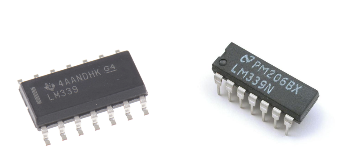
LM339 is a 14-pin IC that has 8 inputs, four outputs, one GND, and one VCC PIN. The comparator IC mostly comes in various SMD and through-hole packages. The LM339 comparator IC has four independent comparators in a single chip, with a wide supply range, making it a famous choice for a range of applications, including electronic home appliances, vacuum robots, wireless applications, motor drive circuits, embedded systems, and industrial automation.
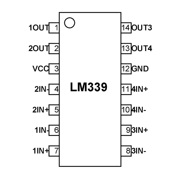
LM339 Comparator IC Pinout
This LM339 IC comparator 16-pin IC mostly comes in SOIC, SSOP, TSSOP, and PDIP packages. The comparator IC is designed and manufacture by Texas Instruments and STMicroelectronics. To use LM339 in your circuit design and application, it is important to understand the role and functions of its different pins.
LM339 PIN Configuration
| PIN Number | PIN Name | Function |
|---|---|---|
| 1 | 1OUT | Output pin of the comparator 1 |
| 2 | 2OUT | Output pin of the comparator 2 |
| 3 | VCC | Positive power supply (between 2-36V) |
| 4 | 2IN- | Inverting the input of comparator 2 |
| 5 | 2IN+ | Non-inverting the input of comparator 2 |
| 6 | 1IN- | Inverting the input of comparator 1 |
| 7 | 1IN+ | Non-inverting the input of comparator 1 |
| 8 | 3IN- | Inverting the input of comparator 3 |
| 9 | 3IN+ | Non-inverting the input of comparator 3 |
| 10 | 4IN- | Inverting the input of comparator 4 |
| 11 | 4IN+ | Non-inverting the input of comparator 4 |
| 12 | GND | Ground Pin of IC |
| 13 | 4OUT | Output pin of the comparator 4 |
| 14 | 3OUT | Output pin of the comparator 3 |

LM339 Op Amp IC Circuit and Working Operation
The LM339 comparator IC consists of four independent operational amplifiers, and each op amp acts as a comparator circuit. The comparator circuit compares the two input voltages and generates the output either low logic (0V) or high logic (+VCC).
The working operation of the comparator circuit is simple and base on the comparison between two input voltages.
Vin+> Vin-
When the non-inverting input is greater than the inverting input, the output goes High (+VCC).
Vin+> Vin-
When the non-inverting input is less than the inverting input, the output goes low (GND).
The detail working operation of the comparator circuit will be further explain with the help of an example.
Problem Statement: Suppose, in some design problem, we want to detect the 5V sine wave signal whenever it crosses the 2.5V threshold. In this scenario, a LM339 IC comparator circuit can be use to perform the task. The frequency of the signal is 2KHz.
For this specific problem, LM339 is configure in a non-inverting operational amplifier. To make the operational amplifier function as a comparator, the op amp is use in open loop configuration. So that the operational amplifier only has two states, i.e., either high (positive saturation VCC), or low (negative saturation 0V). The inverting input of the LM339 op amp comparator is connected to the fixed 2.5V using the voltage divider configuration as shown in the circuit below. The non-inverting input is connected with the input sine wave of 2kHz frequency and 5V amplitude, as shown in the circuit below

In the LM339 comparator circuit shown, the inverting terminal is connected with the two resistors in a voltage divider configuration to make the reference 2.5V.
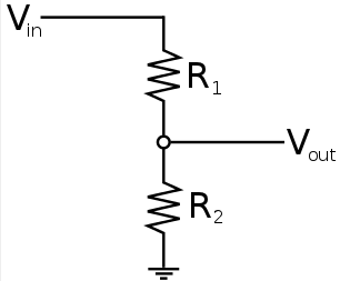
\[ V_{ref} = \frac{V_{CC} \cdot R_1}{R_1 + R_2} \]
\[ V_{ref} = \frac{5 \cdot 10k}{10k + 10k} \]
\[ V_{reference} = 2.5 \, \text{Volts} \]
The non-inverting terminal of the comparator circuit is connected to the input signal of 5V amplitude and 2KHz frequency, as shown in the circuit diagram.
Case I:
When the non-inverting terminal voltage is less than the inverting voltage terminal, the output of the LM339 goes to low saturation (0V) as shown in the output of the comparator circuit below. The LM339 output is a common collector type; therefore, it requires a pull-up resistor at the output to generate high logic.
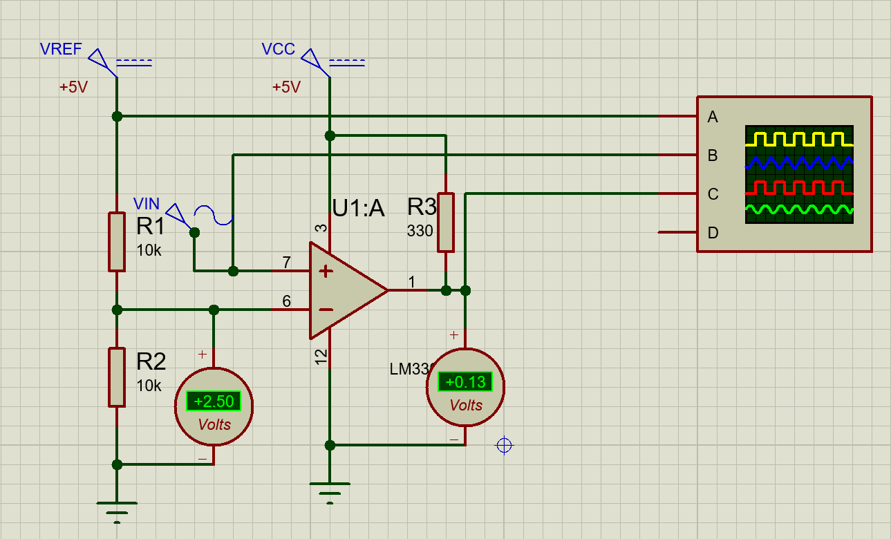
Case II:
When the non-inverting terminal voltage is greater than the inverting voltage terminal (Vref = 2.5V), the output of the LM339 goes into high saturation (5V) as shown in the output of the comparator circuit below.

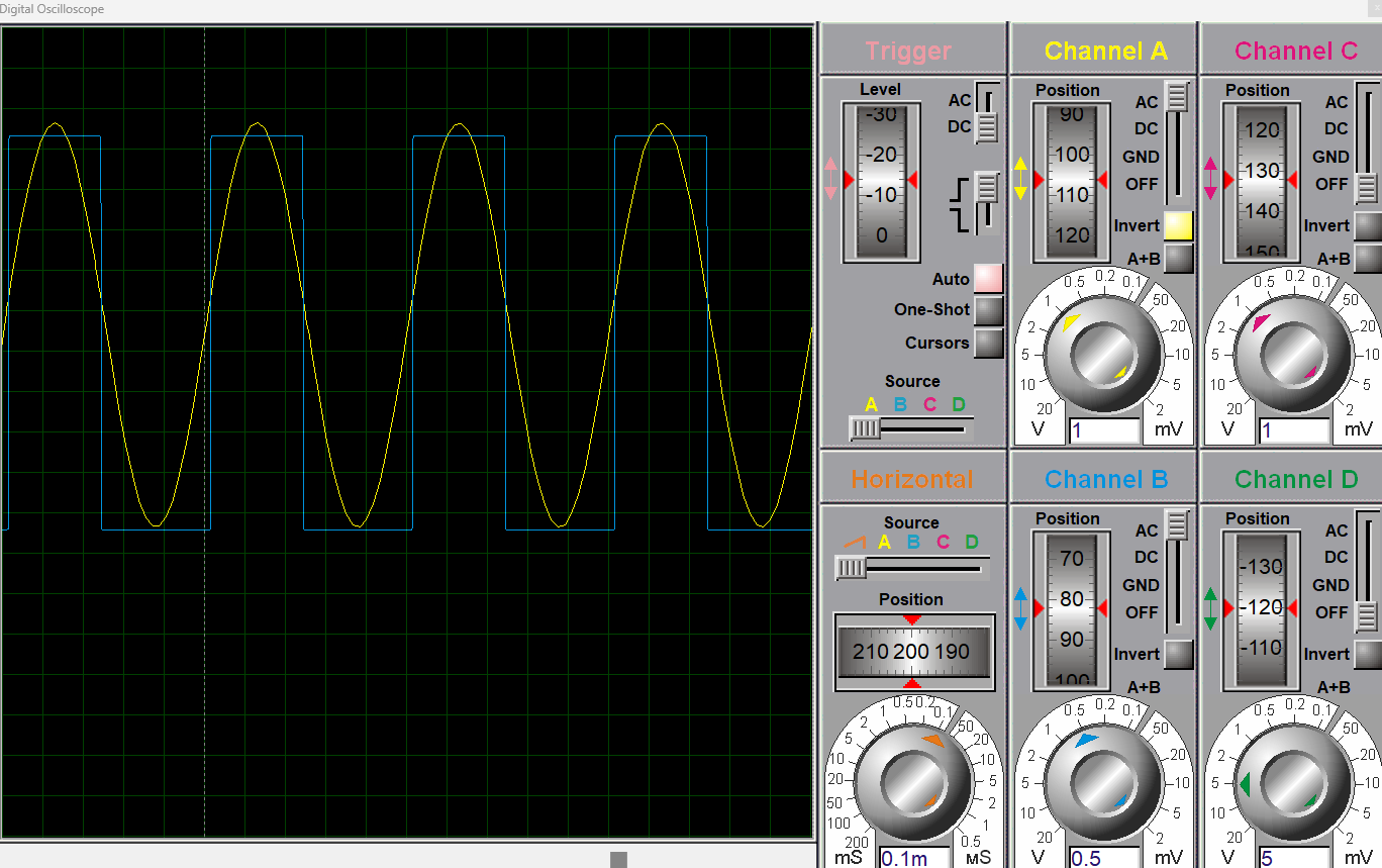
The output waveform of this comparator circuit using the oscilloscope is also shown below. It can be seen that when the sine wave amplitude is less than the reference voltage, the comparator generates zero output. Whereas, when the sinewave amplitude is greater than the reference voltage (2.5V), the LM339 generates the high output (+5V).

Technical Specifications & Parameters
To use LM339 in design, it is important to understand its working operation, design guide, and technical specifications. The technical specifications help the engineers and professionals to understand the limitations of the integrated circuit so that they use LM339 with its full capabilities without crossing the IC limitations.
LM339 Technical Specifications & Parameters
| Parameter | Value | Function |
|---|---|---|
| Supply Voltage Range | 2V-36V | Wide operating range for both low and high-power applications |
| Input Offset Voltage | Typically, 2mV | Shows the LM339 accuracy of voltage comparison |
| Input Bias Current | Typically, 3.5nA | Current flowing into input terminals; affects high-impedance sensor applications |
| Common Mode Rejection Ratio (CMRR) | Typically, 70dB | Shows the comparator’s ability to ensure stable operation even with noise |
| Output Type | Open collector (requires a pull-up resistor at the output) | Ensures AND logic and the capability to interface with different logic families |
| Propagation Delay | Typically, 300ns | Shows the LM339 time taken for the output to respond to input changes |
| Package Type | 14-pin PDIP, SOIC, TSSOP | Available in many packages |
Circuit Design with LM339
Designing circuits with LM339 is simple but needs a good understanding of how operational amplifiers work, pinout details with each pin function, and technical specifications. The LM339 has a simple structure to follow that consists of four independent comparator circuits, and one VCC and GND pin. The four independent comparators allow the designers to compare multiple signals simultaneously, resulting in a reduction of circuit complexity and saving the circuit board space.
However, when designing circuit applications with LM339, there are certain key steps to follow. Following these steps will ensure the effective execution of your application design with LM339.
Reference Voltage Generation (Vref)
The first key step in designing with LM339 is generating a reference voltage. We apply the reference voltage across the inverting terminal, which is use as a reference voltage for comparison with the input voltage. Any voltage that appears on the input terminal that is greater than this reference voltage, LM339 generates a high output. Therefore, generating a stable and exact reference voltage is crucial for designing the comparator circuits with LM339.
You can generate the reference voltage using a voltage divider network or any other precison reference IC. For instance, the supply voltage is 5V, and you need to monitor the 2.5V fixed reference voltage. In such a scenario, a resistor divider network of 10K resistance each is use to generate the 2.5V fixed reference voltage as;
\[ V_{ref} = \frac{V_{CC} \cdot R_1}{R_1 + R_2} \]
\[ V_{ref} = \frac{5 \cdot 10k}{10k + 10k} \]
\[ V_{Reference} = 2.5 \, \text{Volts} \]
Input Circuit Application
Apply yhe input signal at the non-inverting terminal of the comparator LM339. For example, in some design application, a sensor is producing a varying output, we connect this sensor output as an input to the non-inverting terminal of a comparator circuit. Whenever the sensor output exceeds the reference voltage already set across the inverting terminal using the voltage divider network, LM339 states the output state.
Output Voltage of LM339 Comparator
| Condition | Output Voltage |
|---|---|
| When V+ > V- | HIGH (VCC) |
| When V+ < V- | LOW (GND) |
Output Configuration
The LM339 comparator IC has an open-collector output type, which means that a pull-up resistor is require, so that the LM339 can function properly. The pull-up resistor should be between 1k and 10kΩ. The pull-up resistor and output configuration allow the LM339 to easily interface with other logic families.
Common Circuit Applications with LM339 IC
Zero Crossing Detector
Zero Crossing Detector, or simply ZCD, is a useful circuit that is frequently use in AC signal processing, phase control power devices, light dimmers, frequency counters, energy meters, and a sine wave to square wave converter. we can make the zero crossing detector using a LM339 comparator IC.
Connect the inverting terminal of the LM339 comparator circuit with GND (0V). We set the reference voltage across the inverting terminal; therefore, for the zero-crossing circuit, our reference voltage is 0V. Therefore, we connect the inverting terminal with the GND. Now, feed the non-inverting terminal of the LM339 with a sinewave with 1KHz frequency and 5V amplitude as shown in the circuit diagram.

Now, when the sine wave (non-inverting terminal) crosses the zero-reference voltage, LM339 generates a positive high logic (+5V), and when the sine wave is below zero volts, LM339 generates a low logic (0V) as shown in the output waveform of ZCD.
Automatic Street Light Controller using LM339
Another useful design application of LM339 is an automatic street light control design. Using a Light Dependent Resistor (LDR) sensor and an LM339 comparator IC, we can easily design an efficient street light controller.
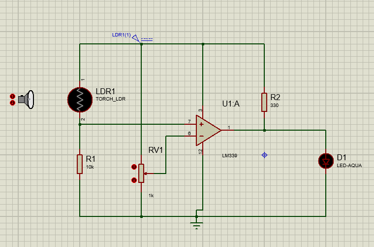
Generate a fix reference voltage using the variable resistor or voltage divider network and apply across the inverting terminal of the LM339 comparator IC. Any other operational amplifier, such as LM741, can also be use for this purpose. LDR and a resistor form a voltage divider network and are applied across the non-inverting terminal of LM339, as shown in the figure. One such common LDR available is GL5528.
During Daytime
During the daytime, the resistance of the LDR is very low, and therefore, the voltage across the input terminal is higher than the reference voltage. This makes the street light in the OFF condition as shown in the circuit diagram below.
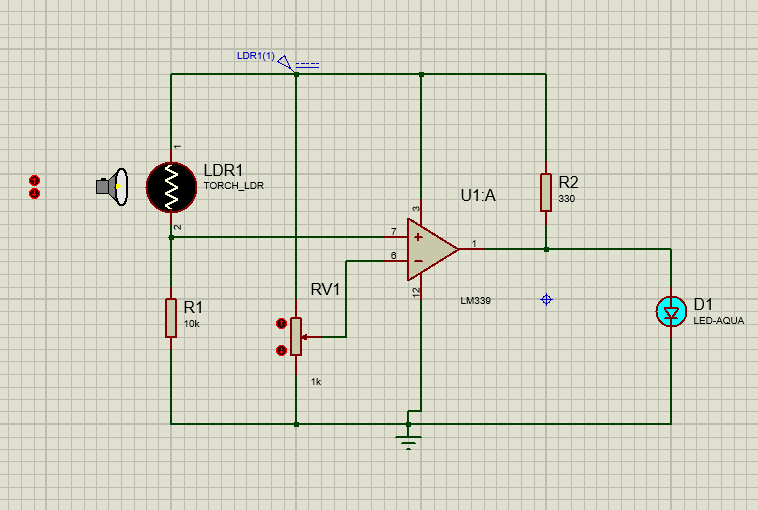
At Night time
However, in the night when the light is no more, the LDR resistance increases drastically, resulting in the reduction of input voltage below the reference voltage. This makes the LM339 change the state from OFF to ON, as shown in the simulation diagram of the street light control circuit below.
This simple but efficient circuit can be use in street lights, security spaces, outdoor lamps, and across motorway roads.
Window Comparator Circuit using LM339
The window comparator is another useful circuit that is often use in electronic applications. A window comparator is a circuit that is use to detect whether the voltage lies within a desire voltage range or not. In a window comparator circuit, two comparators are use alongside to perform the desired operation. The LM339 consists of four comparators; two comparators are use to construct the window comparator circuit. The working operation of the window comparator circuit is as follows;
The upper voltage window is applied at the input of one comparator, and the lower voltage window is applied across the second comparator input, as shown in the circuit shown below. Whenever the voltage is above the specified voltage window, the upper comparator changes its state, and when the voltage is below the specified voltage window, the lower comparator changes its state. The upper voltage comparator indicates the overvoltage condition, and the lower comparator indicates the undervoltage condition, as shown in the output waveform of the window comparator circuit.
The window comparator circuits are mostly employ in electronic circuits such as battery monitoring and voltage detection circuits.


Simulation Results: Battery Voltage Level Indicator with LM339
In this section, I have simulated the 12V battery voltage level indicators in Proteus software using the LM339 comparator IC. In this application, the battery state of charge is shown using the LED indicators.
Battery Voltage Level Indicator
| Battery Voltage | Battery State of Charge | LED Indicator |
|---|---|---|
| 12V | Fully Charged | All LEDs should ON |
| >9V | High | 3V, 6V, and 9V LEDs should ON |
| >6V | Medium | 3V and 6V LEDs should be ON |
| >3V | Low | 3V LED ON |
| <3V | Critically Low | ALL LEDs OFF |
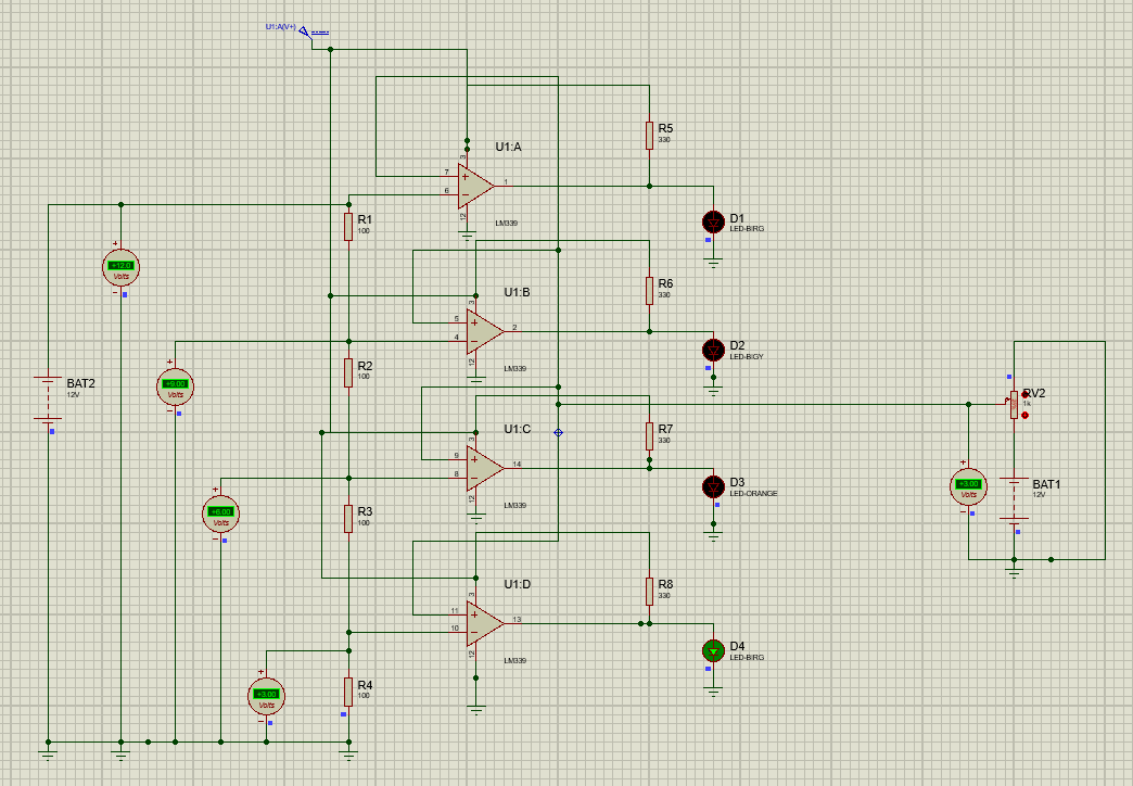
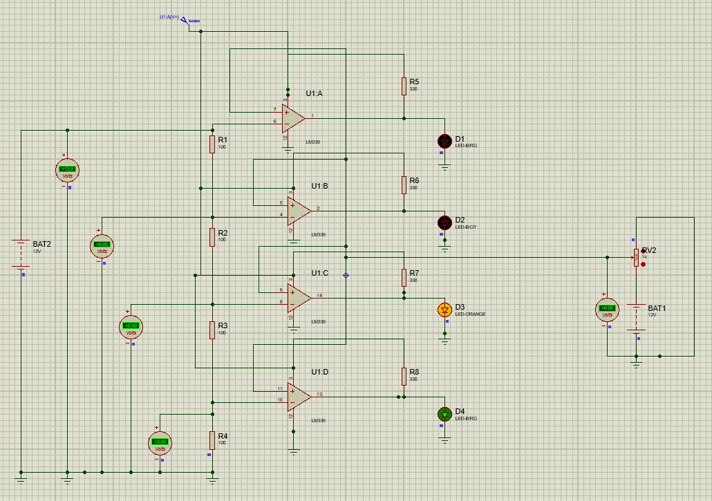
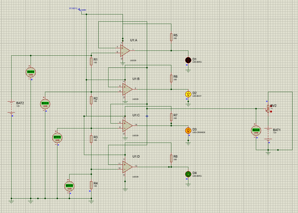
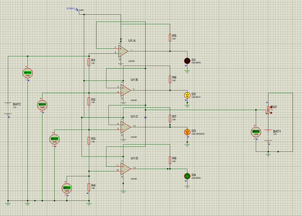
The LM339 consists of four comparators, and in this application, all four comparators are use to make the battery voltage level indicator. One comparator is use for 3V voltage indication, one comparator for 6V voltage indication, one comparator for 9V voltage indication, and one for 12V battery voltage indication.
The circuit concept is that the reference voltages were set using the voltage divider network, and the output of each divider is given at the inverting terminal of each comparator. The actual battery voltage, which is 12V, is given at the non-inverting terminal of each comparator as an input, as shown in the circuit diagram.
As the LM339 has a common collector type, the output of each comparator is pull up using the 330-ohm resistor. Now, connect the different colors LEDs with each output of the comparator to indicate the battery voltage level.
A potentiometer is use to change the battery voltage. When the resistance is at 100% (1kΩ), all LEDs will turn OFF, indicating a critically low voltage level of the battery. When the resistance decreases using the potentiometer, the voltage across the battery increases, and when the battery voltage crosses 3V, the 3V LED will turn ON. Similarly, when the battery voltage crosses 9V, 3 LEDs, including the 9V LED, will turn ON. When the battery voltage approaches 12V, all four LEDs will turn ON, indicating the battery is full, as shown in the circuit diagram below.
Recommended Battery Options
For building a reliable Battery Voltage Level Indicator circuit, choosing a durable and long-lasting battery is very important. Flywing Tech offers high-performance rechargeable batteries that are ideal for educational projects, DIY electronics, and industrial applications.
Battery Voltage is 3V: Battery is LOW
When battery voltage is 6V: Medium Charged
When the battery voltage is 9V: High-level Charged
Battery voltage is 12V: Battery is Full
In the circuit diagram the votlmeter reads 12V, indicating battery status is Fully Charge.
Advantages and Limitations of LM339
The LM339 comparator IC is an advanced, powerful, and famous IC that is widely use in many electronic circuit applications. However, there are some limitations of LM339 as well that must be kept in mind when designing your circuit applications with LM339.

LM339 VS LM393

Conclusion
To sum up, LM339 is a versatile, and powerful comparator IC that is widely use in electronic circuits applications such as vacuum robots, battery monitoring system, automation industry, motor drives, consumer electronics, phase controller, phase meters, frequency counters, and many more. Understanding LM339 comparator IC is essential for electronic engineers, and professionals to efficiently utilize it in their circuit designs. This article had covered the LM339 circuit design, its pinout, technical specifications, and common circuits applications. So, that the reader will get the in-depth understanding of LM339 comparator IC.

Frequently Asked Questions (FAQ)
Q1. What is typical voltage range of LM339?
The typical supply operating voltage range of LM339 comparator IC is between 2V-36V for single supply operation. For dual supply operation it is between ±1V to ±18V.
Q2. Why we need a pull up resistor at the output of LM339 comparator IC?
The LM339 comparator IC has an open collector output type. It is therefore, it requires a pull up resistor at the output. Typically, between 1kΩ-10KΩ.
Q3. Can I use LM339 for battery level indictor circuit?
Yes, you can use LM339 for battery level indicator circuit. In this article, I have use LM339 in battery level indicator circuit.
Q4. What is the difference between LM339 and LM741?
The LM741 is a general-purpose operational amplifier. Whereas, the LM339 is specifically a comparator with faster response, and low power consumption.
Q5. Can LM339 compare low level signals?
Yes, LM339 has a common mode voltage range includes 0V. Therefore, it can compare very low signals.