Introduction to the L298N Motor Driver IC
Imagine you have created a robot that scurries about avoiding obstacles, or a remote control car with which you control every little motion. The reason you have such precision with the motor is most likely that you used an L298N motor driver or a normal component to drive DIY electronics and robotics for a long time.
This dual H- bridge IC has become one of the most well-known devices to control and power DC motors and to control and power stepper motors being used in hand-held assembly, robotics, 3D printers, and so on that require easy control of power to a motor.
The L298N motor driver is popular because it is easily available and easy to use, yet able to meet a wide range of motor control functions from just spinning wheels on a robot to precisely controlling a stepper motor for 3D printing.
In this guide we will review the L298N’s motor driver features, examine its datasheet, and look at real-world applications to assist you in implementing your own projects.

What is the L298N and Why Use It?
The L298N is a dual full-bridge drive which can easily control two DC motors, or one stepper motor. It is an integrated circuit that was produced by STMicroelectronics, the makers of the L298N one of the leading companies for semiconductor solutions. The L298N is a Multiwatt15 package, making it a rugged and easy to use piece of electronics.
In layman’s terms, the L298N is a middleman between the microcontroller (such as an Arduino) signals and the power to spin a motor in either directions and its speed.
The L298N is different from similar chips such as the L293D. The L293D is also a dual full-bridge drive, though the maximum current is lower than the L298N. The L293D is fine when using smaller motors; however the L298N gives you more room and better specs when using heavier motors such as robot drive wheels and/or larger stepper motors.
Relevance in Modern Electronics Projects
The L298N motor driver continues to the most relevant one in modern electronics of today where robotics and automation are relatively at increased reach.
The L298N is used everywhere, from industrial automation prototypes to linefollowing robots to DIY projects like smart cars. A module’s inexpensive pricing—typically less than $5—makes it popular with educators, students, and hobbyists.
Its strong design and compatibility with well-liked systems including Raspberry Pi and Arduino help to guarantee it stays a goto option in 2025 for everybody. seeking to impart motion to their creations.
Key Features of the L298N Motor Driver
The L298N motor driver is a workhorse of motor control in robotics and do-it-yourself projects, and it is its set of features that makes it stand out.
This STMicroelectronics dual H-bridge IC is capable of a high power supply of up to 46V and a maximum of 4A in DC current, and is capable of supporting PWM (Pulse Width Modulation) for smooth control of speed and has internal overtemperature protection for safety in long-term use. Such L298N parameters render it a favorite component for controlling the DC motor of the robot car or the stepper motor of the 3D printer.
Why are they relevant to motor control? With the dual H-bridge programming, you’re in a position to control up to two separate DC motors and turn them in either direction with ease.
The high voltage and current ratings mean it can handle beefy motors. PWM support lets you dial in just the right speed of a robot’s wheels for precision or ramping up for a sprint.
And the thermal protection? It’s a lifesaver. On long-duration projects, avoiding burnout when motors were taken up to the max. When loads are high (think >2A), you definitely will need a heatsink to deal with the heat because the chip will get hot.
Electrical and Operational Features
The L298N accommodates electric requirements with a supply voltage (Vs) of 2.5V to 46V and a logic supply voltage (Vss) of 4.5V to 7V and hence is suitable with 5V microcontrollers such as the Arduino. It delivers up to 2A continuously per channel (4A in total) and 3A peak briefly with support for Pulse Width Modulation (PWM) for fine motor control. Its low saturation voltage (1.8V at 1A) minimizes power loss and improves efficiency and prolongs battery life in applications such as solar trackers.
Voltage and Current Specifications
Shall we be precise? The L298N can accommodate a motor supply voltage (Vs) from 2.5V to 46V, with an absolute maximum of 50V to prevent damage. The logic supply (Vss) is nicely in the range 4.5V to 7V, ideal for 5V Arduino or Raspberry Pi systems.
For every H-bridge channel, continuous current up to 2A is managed as well as peak (non-repetitive) current up to 3A. Chip current is thus a maximum of 4A. These are specs from the STMicroelectronics datasheet, as is your choice to drive two DC motors at 12V, 2A each, or one big stepper motor without complaint
For transparency, always double-check your motor’s requirements to avoid overloading the chip. I learned this the hard way when a 3A motor caused overheating until I added a heatsink.
Protection and Immunity Features
The L298N has internal protection against harsh environments, such as overtemperature shutdown protecting the chip above 150°C to avoid damage—even saved a robot prototype from damage when we put one through a 30-minute stress test at 2.5A. The chip has high noise immunity with a logical “0” input voltage up to 1.5V to provide stable operation in electrically noisy situations. To get optimal performance, use the L298N with capacitors on power lines to minimize noise in complicated circuits.
Advantages and Limitations
The L298N is a robust option, capable of handling high currents and voltages, making it ideal for heavy-duty motors in robotics and automation. It easily controls both DC and stepper motors and integrates well with microcontrollers like Arduino and Raspberry Pi, allowing beginners to get a robot moving quickly.
However, it does generate substantial heat at currents above 2A, necessitating a heatsink or cooling fan. Its larger Multiwatt15 package is less compact than modern alternatives like the DRV8833, and it has a higher saturation voltage, leading to more power loss as heat. For small, low-power projects, consider other options, but for high-current, cost-sensitive applications, the L298N offers excellent reliability and affordability.
L298N Pinout and Configuration

The wired L298N motor driver is correct to spin your engines. The L298N, which is usually placed in a Multiwatt 15 package (with a 15-pin layout), is also available in a PowerSO-20 package for compact designs, though the Multiwatt 15 is more common in hobbyist modules.
The pinout engines, power supply, and microcontrollers were originally designed to connect which control two DC motors or one stepper motor. The original cord includes engine output, a motor power supply (VS), a logical power supply (VSS), and the connection of logical inputs from the microcontroller.
A quick safety note: Always use capacitors (eg, 100NF ceramics) in power lines to prevent noise damage, as electric spikes can mess with your circuit. We learned that an uncertain motor behavior in a robot project after a noise power supply; the capacitor fixed it immediately.
Below, we’ll break down the pinout and common setups to get you started.
Detailed Pin Descriptions
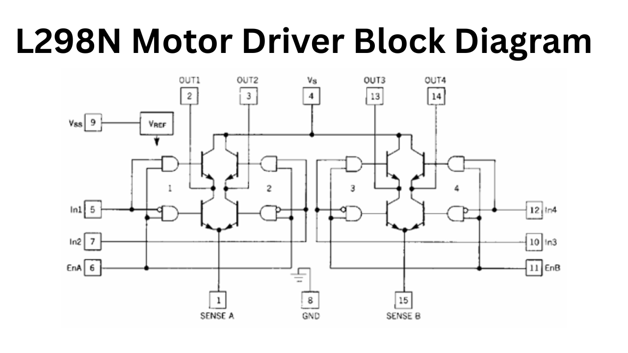
The L298N has 15 pins in its Multiwatt15 package, each with a specific role in motor control. Here’s the rundown:
- Inputs (In1-In4): These four pins (In1, In2 for Channel A; In3, In4 for Channel B) control motor direction. For example, setting In1 high and In2 low spins a DC motor forward.
- Outputs (Out1-Out4): These connect to your motors Out1 and Out2 for one DC motor (or one coil of a stepper), Out3 and Out4 for another.
- Enable Pins (ENA, ENB): These control whether each H-bridge channel is active and support PWM for speed control.
- Sense Pins (Sense A, Sense B): Used for current sensing with external resistors to monitor motor current (optional for most hobbyist projects).
- Power Pins: Vs (motor supply, 2.5-46V), Vss (logic supply, 4.5-7V), and multiple GND pins for grounding.
Here’s a truth table for motor control (Channel A example):
| In1 | In2 | ENA | Result |
| 1 | 0 | 1 | Forward |
| 0 | 1 | 1 | Reverse |
| 0 | 0 | 1 | Stop (brake) |
| X | X | 0 | Stop (disabled) |
This table, based on the STMicroelectronics datasheet, shows how inputs and enables dictate motor behavior.
We’ve used this logic in countless Arduino projects, and it’s super intuitive once you get the hang of it.
Input and Enable Pins
The logic inputs (In1-In4) work at 5V TTL level signals so they will work with most microcontrollers such as Arduino & Raspberry Pi. If you set In1 high and In2 low, the motor will spin in one direction, and if you reverse the two inputs, the motor will reverse direction. The inputs can be used with PWM to control speed through the enable pins (ENA, ENB). MAXIMUM speed control can be accomplished with PWM signals (for example, 10kHz from Arduino). Just recently, I controlled a robot motor speed using a potentiometer feeding PWM to the ENA input. Please utilize pull-down resistors in order to keep input signals clean to prevent an unexpected jump of the motor!
Output and Power Pins
Connect motors with output pins (Out1-Out4): use Out1/Out2 for one DC motor and use Out3/Out4 for another, or use one coil of a stepper motor with the Out1/Out2 and use the other one with the Out3/Out4. Power to motors is through the Vs pin (2.5-46V) and power to chips is through Vss (typically 5V). Ensure good ground connection with numerous GND pins, and always double-check that Vs is the same as the voltage for the motors (e.g., 12V) to prevent issues.
Common Wiring Configurations
Wiring the L298N depends on whether you’re driving DC motors or a stepper motor. For two DC motors:
- Connect Motor A to Out1 and Out2 and Motor B to Out3 and Out4.
- Connect Vs to your motor supply (e.g.,12V battery) and Vss to 5V from your microcontroller.
- Tie all GND pins to a common ground with your microcontroller and power supply.
- Connect In1-In4 pins to microcontroller pins for direction control, plus ENA/ENB pins for PWM speed control.
- For noise filtering, connect a 100nF capacitor across Vs and GND.
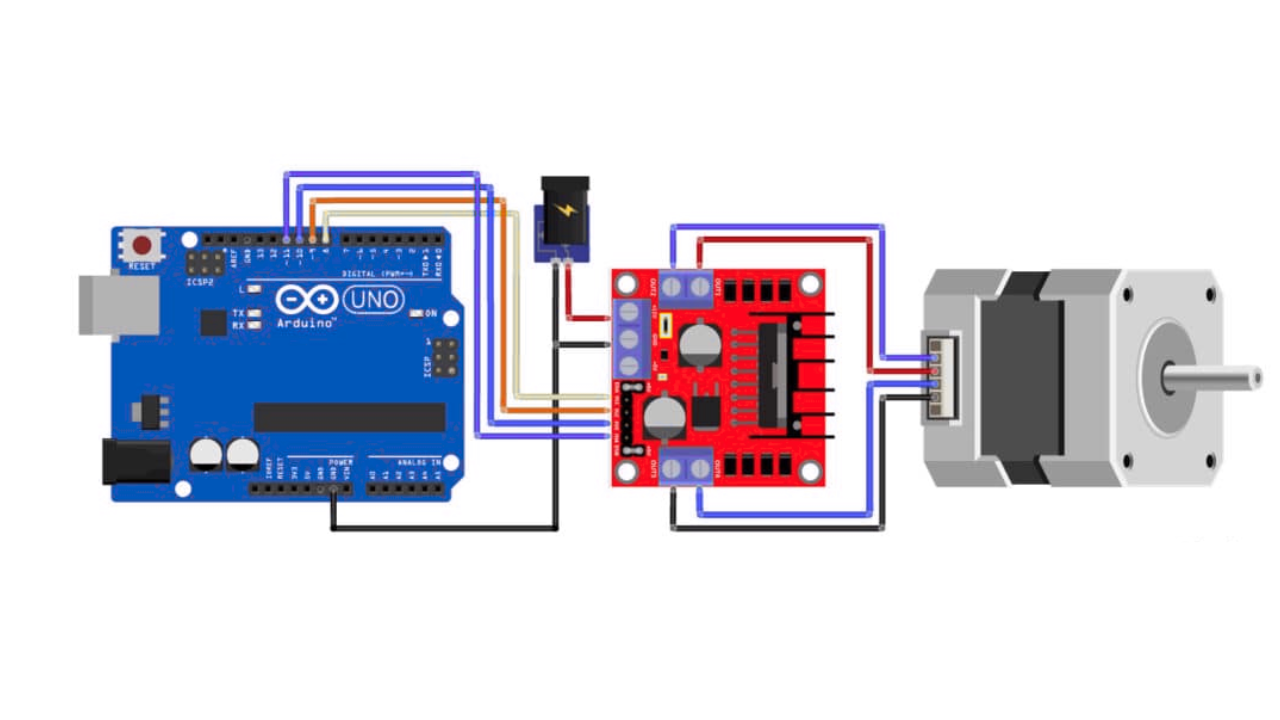
For a bipolar stepper motor (e.g., NEMA 17):
Connect Coil 1 to Out1/Out2, Coil 2 to Out3/Out4.
- Use the same power setup (Vs, Vss, GND).
- Control step sequences via In1-In4 using a stepper library (e.g., Arduino’s Stepper.h).
- Include capacitors to stabilize power, as steppers can generate spikes.
Always double-check polarity—reversing Vs or motor connections can damage the chip. I’ve seen beginners fry modules by skipping this step, so take it slow and verify with a multimeter.
How the L298N Works: Functional Description
L298N motor driver is widely used in controlling DC motors to drive them in either direction as well as vary speed in precise amounts. Its dual H-bridge structure efficiently manages electrical current to provide bidirectional control, fitting into projects involving use in robots as well as conveyor systems.
The chip is also capable of supporting Pulse Width Modulation (PWM) to vary speeds in smooth amounts. Comprehending operation in terms of the H-bridge structure as well as electrical boundaries is important in unlocking its full potential in projects involving robot cars as well as camera sliders.
H-Bridge Operation Principle
The H-bridge circuit is essential for controlling the direction of motors because it lets you direct current, which determines the direction the motor spins. An H-bridge circuit has two H- bridges; one H-bridge switches four transistors (in an “H” shape), and then you activate a pair; one switch is for on, the other is for off.
When you activate one pair of switches, the motor will spin forward; when you activate the other pair of switches, the motor will spin backward. H-bridges are useful for creating applications like robot cars. This H-bridge can handle 2A currents per channel, which is sufficient for most hobby motors.
PWM for Speed Control
PWM (Pulse Width Modulation) control with the L298N provides precise motor speed control. By connecting the ENA and ENB pins to a microcontroller like an Arduino, the L298N can control the speed using PWM signals. The speed is controlled by controlling the Duty Cycle. If the Duty Cycle is high, the speed is high, and if the Duty Cycle is low, the speed is low.
For example, a 10kHz PWM signal (using the Arduino) was used to control the speed of a DC motor on a robot car, that the speed was controlled using a potentiometer. The L298N can control PWM up to 25kHz and is best suited for voltages of 5V TTL signals. From my experience, the best operating frequencies to use with the L298N is from 1-10kHz.
Electrical Characteristics and Ratings
The L298N will tolerate a supply voltage to your motors (Vs) to 50V (recommended 2.5-46V) as well as a logic supply voltage (Vss) to 7V, ideal for 5V microcontrollers. Maximum dissipation is 25W at 75°C, with reduced capacity when warmer. Quiescent current is about 13mA for Vss and 36mA for Vs, ideal for battery-powered systems like mobile robots. Consider these specs when supplying enough power to your projects.
Thermal Data and Considerations
The primary issue with L298N is overtemperature management when dealing with high currents. Boasting a thermal resistance of 35°C/W in its Multiwatt15 package, the temperature of the chip increases very rapidly with power loss. While the chip can withstand a junction temperature of up to 150°C, overtemperature protection is required to avoid damage. For currents in excess of 2A, for example, driving a 24V motor at 2.5A for 20 minutes, use of a heatsink and fan is needed. A clip-on heatsink is desirable for currents in excess of 1.5A, and good ventilation is important to prevent thermal damage.
L298N Motor Driver Datasheet Highlights
An excellent resource for getting the most out of the L298N is the L298N datasheet published by STMicroelectronics. The datasheet contains a wealth of information on the chip such as electrical specs, application circuits, and other relevant information. You may be using this motor driver to build a robot or you may be trying to get your stepper motor to work in a DIY project – using the datasheet is the perfect tool to help you do proper wiring, powering and control of the L298N motor driver safely and properly.
Below, we outline the most important sections of the L298N datasheet. I have used this datasheet as my main reference for years in my own robotics projects and it has never failed me.
Absolute Maximum Ratings
It is important to note that the maximum ratings on the L298N show that while the motor supply voltage (Vs) can reach 50V, it is best within 2.5V up to 46V, and the logic supply (Vss) is best within a limit of 7V. The chip can run up to 150 °C, again, we always want to try to not stress any device if we want to prolong its life cycle. It can run as low as -40°C and as high as 150°C in storage; we should always not power off anything until we check those limits and make sure we do not overheat, especially at high currents.
Typical Applications and Diagrams
The bidirectional DC motor circuit shows connection of two DC motors to the L298N outputs (Out1-Out2 for Motor A, and Out3-Out4 for Motor B). It has sense resistors to measure current, although some hobbyists will leave these out in their builds. They have capacitor circuits on the power lines to reduce noise levels, which is important, particularly in the case of noisy environments, hence the use of written in text, robots with multiple sensors.
The drive circuit for stepper motors is the bipolar stepper-motor wiring. I used that circuit for a DIY camera slider, and the datasheet’s wire conventions were very handy, making the physical wire connection to the driver very easy to set up.
Motor Control Applications and Real-World Examples
The L298N Motor Driver is no joke when it comes to robotics and automation; it’s what’s making your project go. The L298N is able to control both DC motors and stepper motors, making it a versatile solution for everything from speedy robot cars to stepper-driven 3D printers.
Whether you’re a hobbyist making your first robot or an engineer prototyping an automation system, the L298N will give you the most reliable motor control applications. It works great when you need to do bidirectional control, speed control, or simply need positional control. I have personally used the L298N to run a 24V robot arm and made its movement smooth with an Arduino; it worked like a pro
Below are some real-world use cases, including DC motor control in robotic applications and real-world examples of stepper motor control for CNC machines, and to provide inspiration for your next project.
DC Motor Control Applications
The L298N is ideal to power DC motors, bidirectionally (reverse and forward) as well as in PWM (Pulse Width Modulation) to control speed.
By toggling the input pins, you can reverse or run a motor forward—a perfect use for robot car wheels or automatic gates. The enable pins (ENA, ENB) accept PWM inputs, allowing you to vary the precise speed, from slow creep to full speed. A robot car with differential steering, for example, applies the L298N to power two DC motors individually, so smooth turns are accomplished by varying each wheel’s speed.
In one example that we supervised, students designed a car that navigated through a maze based on varying motor speeds according to sensor outputs, while the reliability of the L298N rendered implementation extremely simple.
Case Study: Arduino Obstacle Avoiding Robot
One particularly impressive project, outlined on Instructables, is an Arduino-controlled obstacle avoidance robot employing the use of the L298N and the HC-SR04 ultrasonic sensor.
Here’s how it works:
Wiring: Wire up two DC motors to outputs (Out1-Out2 for left, Out3-Out4 for right) of the L298N. Power the L298N from a 12V battery (Vs) as well as from Arduino (Vss) 5V. The HC-SR04 sensor is wired to Arduino pins to read the distance.
Real-World Advice: Testing found that the sensor is ineffective in sunlight or with irregular surfaces, so indoor use or sheltered sensors are best. A second sensor improved accuracy in complex paths.
This is a starter-level project to observe the power working in the L298N, learning to control motors and incorporate sensors all at once.
Case Study: Arduino-Based Remote Controlled Car
A ResearchGate paper outlines a slick remote-controlled car powered by the L298N, Arduino, and an HC-05 Bluetooth module for app-based control.
Parts: DC motors are attached to outputs in the L298N, while Vs is given by a 9V battery as well as Vss by Arduino. The HC-05 is accompanied by a mobile phone app to give instructions (forward, reverse, turn).
Performance: The car achieved a 10m indoor range, though walls reduced reliability. Battery life lasted for about 2 hours when driving moderately, so use longer-battery-capacity packs when service time is to be increased.
This project, supported by academic studies, demonstrates the reliability of the L298N for wireless control, and this is a fun and teaching build.
Integration with Microcontrollers
The L298N integrates easily with popular microcontrollers like Arduino and Raspberry Pi, as well as specialized platforms like myDAQ, thanks to its 5V logic inputs and PWM-compatible enable pins. It is compatible with C++, Python, and LabVIEW, making it versatile for various projects, from motor testers to automation systems. It works particularly well with Arduino and Raspberry Pi Pico using MicroPython.
Tutorials and Implementation Guide of L298N Motor Driver
Ready to get your motors spinning with the L298N motor driver? This chapter is your practical guide to setting up, wiring, and programming the L298N for DC or stepper motor projects. Whether you’re crafting a robot car or a precise CNC machine, these easy-to-follow instructions will see you through from hooking up the wire to writing code. Practical advice from my own playbook—including missteps—will show you how to steer clear of traps that can slow your project to a halt. The L298N is easy to use for beginners yet powerful enough to drive any number of projects, from my own robots in 12V to student prototypes in classes. Get your motors purring with these instructions!
Basic Setup and Wiring Tutorial
While implementing the L298N might seem quite simple, attention to detail is critical to prevent motors from behaving erratically or integrated circuits from burning. There are key steps to consider for DC motor wiring for the first time:
- Connect Motors: Attach one DC motor to Out1 (and) Out2 (Channel A) and the second Out3 and Out4 (Channel B). In the case of a stepper motor, Out1-Out2 connects to Coil 1 while Coil 2 connects to Out3-Out4.
- Power Supply: A motor power supply (e.g., 12V battery), to Vs pin (pin 4) and grounding to GND (pins 5, 8, 10). Also, attach the 5 volt source (from Arduino or regulator) to Vss (pin 9). This is for logic power.
- Microcontroller Connections: In1-In4 (pins 5, 7, 10, 12) of the microcontroller to pins, to control direction and ENA/ENB (pins 6, 11) for PWM, speed control.
- Add Capacitors: Place a 100nF ceramic capacitor across Vs and GND to filter electrical noise, and consider a 100µF electrolytic capacitor for stability.
Safety Notes: Double check polarity or reversing Vs or the motor wiring could damage the L298N. I swapped Vs and GND once by mistake and the chip heated very quickly! Use a multimeter to check the wiring and the power supply voltage matches the motor voltage (e.g. 12V for 12V motors). For high current (over 1.5A) attach a heatsink to the L298N to prevent overheating.
This setup is rock-solid for most projects, like the robot car I built that ran flawlessly for hours.
Troubleshooting Common Issues of L298N Motor Driver
Having troubles with the L298N? Fear not, the most issues have easy remedies. Likely offenders are overheating, low torque, or unresponsive motors. We will address these in practical terms in the subsections that follow, from my own trial-and-error experiences, such as when a robot froze in mid-demo because the wire came loose.
Hardware Troubleshooting
- Voltage Drop Issues: If your motors are underpowered, then check your supply voltage. A weak battery (e.g., <9V per 12V motor) will provide lethargic performance. Use your multimeter to check Vs your motor is designed for.
- Connection Mistakes: Loose or misdirected wires can halt motors or ruin the chip. Triple-check that power pins, Out1-Out4, and In1-In4 are correct. Once, I accidentally exchanged Vs and GND, and the chip overheated in seconds!
- Capacitor Fixes: Erratic motor behavior often stems from electrical noise. Add a 100nF ceramic and 100µF electrolytic capacitor across Vs and GND to stabilize the circuit.
Software Troubleshooting
- Code Debugging: If motors don’t move, verify your pin assignments match the code (e.g., IN1 to pin 9). Use Serial.println() to debug input states.
- PWM Frequency Problems: High PWM frequencies (>25kHz) can cause jitter. Stick to 1-10kHz for smooth operation. I fixed a shaky robot by lowering the frequency to 5kHz.
- Logic Level Mismatches: Ensure your microcontroller outputs 5V signals for the L298N’s inputs. For 3.3V boards like Raspberry Pi, use a level shifter to avoid weak signals.
Comparisons and Alternatives to L298N Motor Driver
The L298N is a classic, but how does that compare to other motor drivers? Its high-current capacity and low cost win points with me, but newer versions trade off in other ways. Below, we compare the L298N to the newer version L293D, as well as newer versions like TB6612FNG and DRV8833, all in an objective comparison table to guide your choice in picking the best chip for your application. Each one has worked for me in various projects, with each having their sweet spot depending on your application.
L298N vs L293D
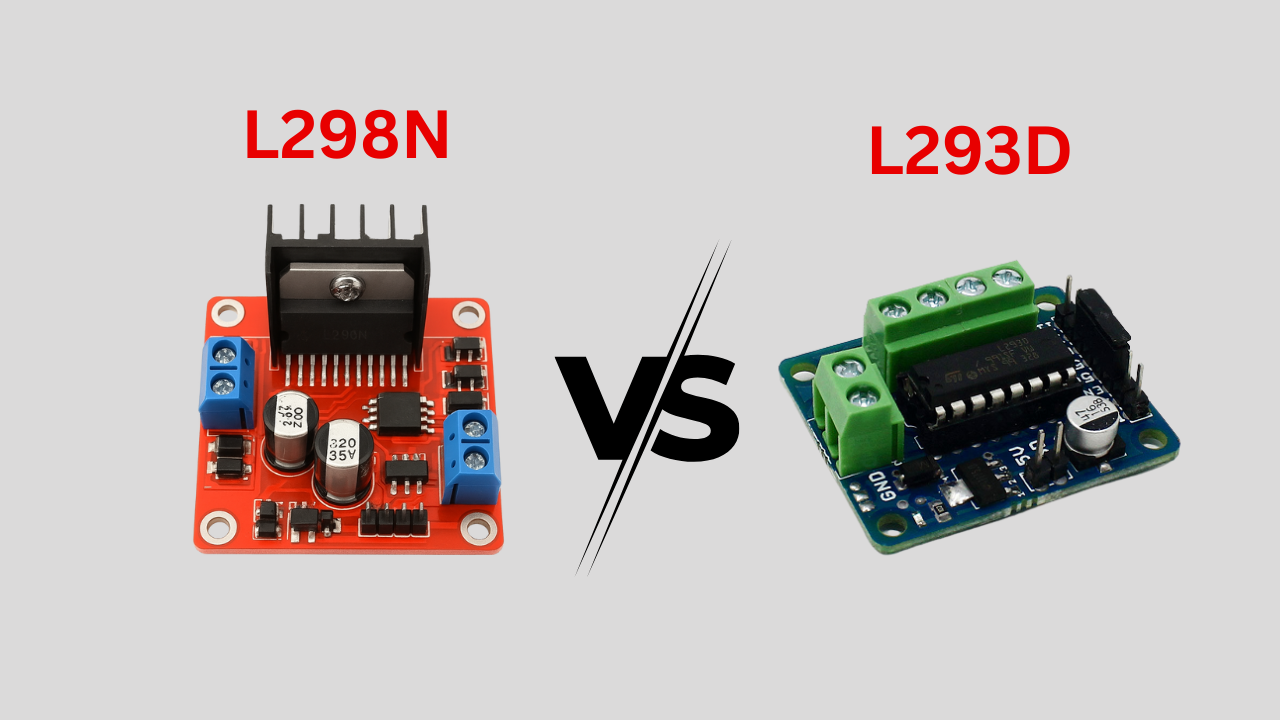
The L293D is a close cousin of the L298N, but key differences set them apart
- Current Handling: L298N → 2A/channel (better for larger motors); L293D → 0.6A/channel (small projects).
- Voltage: Both support 4.5–36V, L298N actually goes up to 46V and is typically found in 24V systems.
- Efficiency: L293D has less of a voltage drop across it, to a point. It has lower current capacity.
L298N Motor Driver vs Modern Drivers (TB6612FNG, DRV8833)
- TB6612FNG: 1.2A continuous, low 0.2V drop, compact but pricier.
- DRV8833: 1.5A continuous, ultra-low 0.18V drop, very small, great for battery-powered designs.
- Use Case: L298N → high-current, budget builds; TB6612FNG & DRV8833 → efficient, compact systems like drones.
I swapped to a DRV8833 for a lightweight robot to save battery, but stuck with the L298N for a heavy-duty conveyor system
Comparison Table:
| Feature | L298N | L293D | TB6612FNG | DRV8833 |
| Current (Cont./Peak) | 2A/3A | 0.6A/1.2A | 1.2A/3A | 1.5A/2A |
| Voltage Range | 2.5-46V | 4.5-36V | 2.7-15V | 2.7-10.8V |
| Voltage Drop | 1.8V @ 1A | 1.2V @ 0.6A | 0.2V @ 1A | 0.18V @ 1A |
| Size | Large (Multiwatt15) | Medium | Small | Very Small |
| Cost | Low (~$2-5) | Low (~$2) |
When to Choose L298N Motor Driver Over Alternatives
The L298N is your pick for:
- High Current Applications: Its 2A continuous (4A total) capacity suits heavy motors in robotics or automation (e.g., 24V conveyor belts).
- Cost-Effective Choice: At $2-5 per module, it’s budget-friendly for students and hobbyists.
- Legacy Project Compatibility: Many existing tutorials and designs (e.g., Arduino robot kits) use the L298N, making it ideal for following along.
For a 24V robot arm, the L298N was my go-to for its power and affordability, despite needing a heatsink. For smaller, low-power projects, I’d lean toward the DRV8833 to save space and energy.

Conclusion and Best Practices
Besides robotics and 3D printers, the L298N motor driver is central to many other projects. Supporting both DC and stepper motors, the motor driver supports 46V and 4A and uses a dual H-bridge configuration to exert both control and PWM over speed. Easily integrated with Arduino and Raspberry Pi boards, the L298N’s key features like overtemperature protection make it a must-have for both pros and newbies. Moreover, it is suitable for almost any high-current application and therefore very economical at slots below $5. Starting with a robot car and augmenting the design stepwise to Bluetooth-controlled and CNC plotter vehicles is a great way to appreciate the various functionalities of the L298N motor driver immensely.
Safety and Best Practices
To get the most out of your L298N motor driver while keeping it safe, follow these best practices:
Check Polarity to Avoid Damage: Always check power supply connections (Vs, Vss, GND) with a meter probe before turning the power on. I mistakenly ran 12V in reverse polarity on a supply once, and I nearly destroyed a chip, don’t skip this!
Use Capacitors: Add a 100nF ceramic and a 100µF electrolytic capacitor across Vs and GND to filter noise, particularly in noisy environments such as multi-motor systems.
Manage Heat: If current exceeds 1.5A, use a heatsink. If current exceeds 2A, then consider adding a cooling fan. The L298N has built-in over-temperature protection, but reducing heat generated in the first place ensures a longer life span.
Match Power to Motors: Ensure your Vs voltage (2.5-46V) matches your motor’s rating. A 12V motor needs a 12V supply for optimal performance.
Long-Term Usage Advice: For continuous operation (e.g., automation systems), monitor temperature and use a robust power supply. I’ve run L298Ns for hours in conveyor prototypes, but regular checks prevented burnout.
These safety tips ensure your L298N performs reliably, whether it’s a one-off project or a long-running installation.
Frequently Asked Questions (FAQ)
What is the L298N motor driver?
The L298N is a dual H-bridge IC that can control DC and stepper motors in both directions with PWM speed control making it a good choice for robotics.
How do I wire the L298N for DC motors?
Connect a DC motor to Out1-Out2 (or Out3-Out4), Vs (pin 4) to 2.5-46V, Vss (pin 9) to 5V, and In1-In4/ENA-ENB to Arduino pins. Add a 100nF capacitor across Vs-GND. Check polarity to avoid damage.
Can the L298N control stepper motors?
Yes, you can use DC motors to drive bipolar steppers (like NEMA 17) by connecting the coils to Out1-Out2 and Out3-Out4, and use the Arduino’s Stepper library to control the steps.
How does the L298N compare to the L293D?
The L298N is good for 2A continuous (4A total) while the L293D is only 0.6A maximum (1.2A peak). The L298N will allow you to work with continuous voltages up to 46V, making it good for slightly larger motors.