Introduction
The AT24C256 EEPROM is one of the most widely used non-volatile memory ICs in embedded systems, valued for its simplicity, reliability, and ease of integration using the I2C communication protocol. This IC has a storage capacity of 256 Kbit (32 KB), and it provides a way for storing critical data such as configuration parameters, calibration values, system logs, and user settings, even when the power is turned off.
Modern embedded and electronic designs often have limited memory and are mostly reserved for firmware. Therefore, AT24C256 provides the solution for data storage. Whether you are working with Arduino, STM32, or ESP-based systems, this EEPROM offers a cost-effective and flexible way to expand memory without adding complexity to the design.
With many advantages, it is still important to use EEPROM properly as per the design reference guide mentioned in its datasheet and follow the best design layout practices to prevent noise and data loss. This technical tutorial will help you guide “How to use AT24C256 EEPROM” as per the design guide, and ensure your project will not have any hardware and software-related issues.
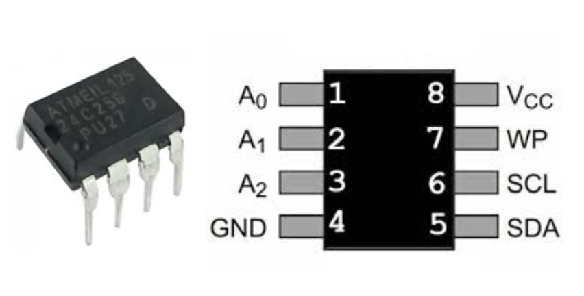
AT24C256 EEPROM Pinout and Description
Before we start designing with AT24C256 EEPROM, it is important to first understand the IC pinout, supported communication protocol (I2C), power requirements, and functionality of each pin and their use. This EEPROM uses an 8-pin package and communicates via the I2C protocol, making it simple to connect with most microcontrollers such as Arduino, STM32, and ESP-based boards.
Pinout of AT24C256 EEPROM IC
I2C Communication Protocol of AT24C256 IC
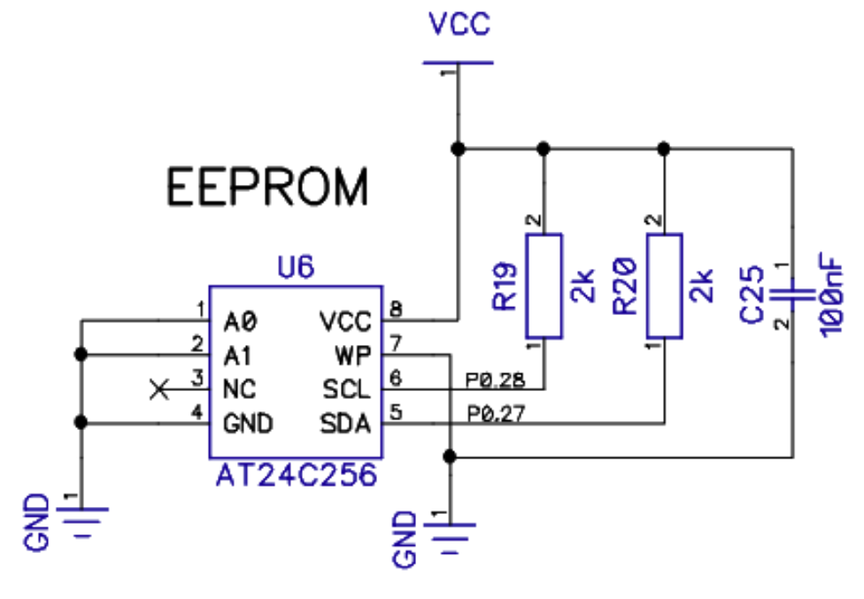
The AT24C256 EEPROM communicates using the I2C two-wire serial communication interface. It allows a microcontroller like STM32, ESP32, and an AVR microcontroller to communicate with multiple devices using just two lines: SDA (data) and SCL (clock).
Both SDA and SCL lines require a strong pull-up, which can be done by connecting both wires with 3V3 (VCC) using a 4.7K ohm resistor. This is important because the I2C lines are open-drain outputs, which means devices can only pull the lines (SDA and SCL) to low. In other words, they cannot drive the line HIGH. The typical application circuit of this AT24C256 EEPROM is shown below as a reference design for the embedded or PCB designers. This can be used as a “plug-and-play” circuit for any embedded application, regardless of the controller or design application.
Typical Packages of AT24C256 EEPROM
The AT24C256 EEPROM is available in multiple package types to suit different PCB design requirements, assembly methods, and application sizes. It is important to carefully select the EEPROM IC package for your design. For example, for design application SMD is prefereable choice, and THT is good for tabletop testing, breadboard, and prototype designs.
AT24C256 Package Comparison Table

Key Specifications of AT24C256
Next step is to understand the key specifications of AT24C256 EEPROM to correctly and designing a reliable embedded system with EEPROM. The detailed key specifications of this IC can be found and retrieved from its datasheet.
AT24C256 Key Specifications Table
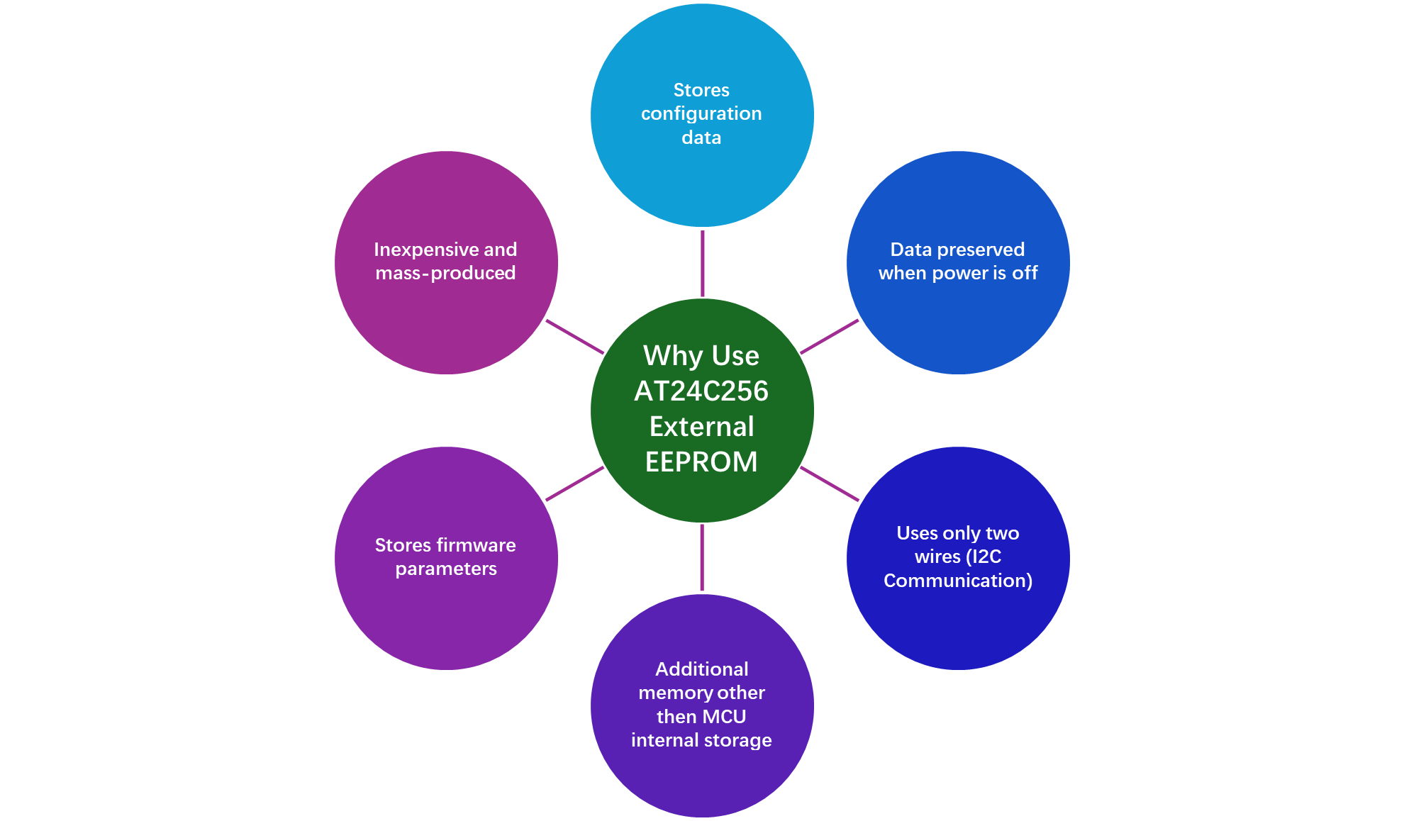
Why Use an External EEPROM?
One can think that most of the microcontrollers come with internal memory, so why do we need the external EEPROM memory devices like AT24C256 for your embedded design application? This is because the internal memory is often reserved for firmware-related functions, and it is limited in most cases. In such cases, one can think of interfacing the EEPROM with its microcontroller for additional storage space for configuration data, logs, and for temporary storage buffer stage.
AT24C256 Interface Circuit with Microcontroller
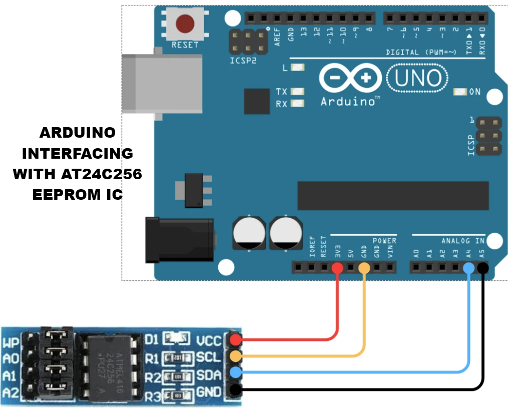
This section describes the technical guide on how to connect the AT24C256 with your microcontroller for effective communication and robust design. The AT24C256 communicates via I2C, so the interface requires SDA and SCL connections, pull-up resistors, and proper power design.
Basic AT24C256 Interface Connections
I2C Communication with AT24C256
The circuit connection of AT24C256 will remain the same whether you interface/connect it with the STM32, ESP32 microcontroller, or Arduino UNO board. I have shown the physical connection/wiring diagram of the EEPROM IC with the Arduino UNO Board. The configuration of pins may be followed for any microcontroller used in the design. However, the firmware code may vary when interfacing with different microcontrollers. The example code of AT24C256 with Arduino UNO is also shown below for the starting point in firmware development.
#include <Wire.h>

#define EEPROM_ADDR 0x50  // Base I2C address (A0,A1,A2 = GND)
#define PAGE_SIZE 64      // AT24C256 page size in bytes

// Function to write a byte to a specific EEPROM address
void writeEEPROM(unsigned int eeAddress, byte data) {
  Wire.beginTransmission(EEPROM_ADDR);
  Wire.write((int)(eeAddress >> 8));   // MSB of address
  Wire.write((int)(eeAddress & 0xFF)); // LSB of address
  Wire.write(data);
  Wire.endTransmission();
  delay(5); // Wait for write cycle to complete (~5ms)
}

// Function to read a byte from a specific EEPROM address
byte readEEPROM(unsigned int eeAddress) {
  byte rdata = 0xFF;
  Wire.beginTransmission(EEPROM_ADDR);
  Wire.write((int)(eeAddress >> 8));   // MSB of address
  Wire.write((int)(eeAddress & 0xFF)); // LSB of address
  Wire.endTransmission();

  Wire.requestFrom(EEPROM_ADDR, 1);
  if (Wire.available()) rdata = Wire.read();
  return rdata;
}

void setup() {
  Wire.begin();       // Initialize I2C
  Serial.begin(9600); // Initialize serial monitor

  // Example: Write 123 to address 0x0000
  writeEEPROM(0x0000, 123);
  Serial.println("Data written to EEPROM!");

  // Example: Read from address 0x0000
  byte value = readEEPROM(0x0000);
  Serial.print("Read value: ");
  Serial.println(value);
}

void loop() {
  // Optional: Add repeated read/write tests here
}
Servo Motor Control Using AT24C256
At this point, we have solid understanding of AT24C256 EEPROM IC pinout, basic circuit, it’s I2C communication protocol and its wiring diagram. Now, we have prepared to design a circuit of EEPROM IC for any embedded system.
Below is the practical application of servo motor control using AT24C256 EEPROM IC.
A practical application of the AT24C256 EEPROM in embedded systems is servo motor control, where the EEPROM stores servo positions, calibration offsets, and motion sequences. In this setup, a microcontroller reads and writes position data from the EEPROM via the I2C interface, using SDA and SCL lines with proper pull-up resistors.
On startup, the MCU retrieves the stored positions and generates PWM signals to move the servo to the desired angles. During operation, new positions or motion sequences can be dynamically written to the EEPROM, allowing the system to remember movements even after power loss. This approach is ideal for robotic arms, automated mechanisms, and IoT devices, providing reliable, non-volatile storage of critical servo configurations while freeing the MCU’s internal memory for other tasks.
Data Loss Prevention Strategies
Even with proper hardware circuit design, it is possible that the data might be lost when using the AT24C256 EEPROM. Therefore, it is essential to properly use hardware, firmware, and usage strategies to significantly reduce the risk of data corruption or loss.

Common AT24C256 Failures in Embedded Systems
Understanding the typical failures of the AT24C256 EEPROM is essential for designing reliable embedded systems. These failures often occur due to improper usage, environmental conditions, or design oversights, and knowing them helps prevent data loss, communication errors, or device damage.
⚠️ Common AT24C256 Issues & Causes
Hardware Best Design Practices
Even with all the practical and datasheet knowledge of the IC that is being used in your design application. One design can still end up a failure if some of the best design practices are not followed. In this section, I have mentioned the best design practices that designers can follow to prevent failure and communication errors with microcontrollers.
AT24C256 Design & Best Practices
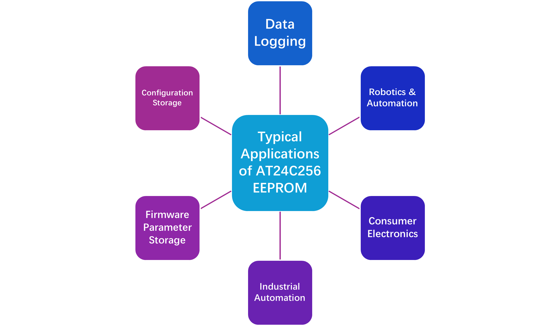
Typical Applications of AT24C256 EEPROM
The AT24C256 EEPROM is a versatile non-volatile memory widely used in embedded systems to store critical data, configuration settings, and calibration parameters. Its I2C interface, compact size, and reliable data retention make it ideal for a broad range of applications. The most common applications where this AT24C256 EEPROM IC is used are listed below.
Common Use Cases of AT24C256
How to Choose the Right EEPROM for Your Project
At last, choosing the right EEPROM IC is crucial to ensure data reliability, system compatibility, and long-term performance in embedded applications. The choice depends on memory size, interface type, endurance, voltage levels, and specific project requirements.
Key Factors to Consider
Memory Capacity :
- AT24C256 (32KB) : Ideal for storing calibration data, configuration parameters, and moderate logging.
- AT24C512 (64KB) : Suitable for more extensive data logging or multiple device settings.
- AT24C1024 (128KB) : Best for high-volume industrial logging or multi-sequence storage.
Interface Type:
- I2C EEPROMs (AT24C02): Great for minimal pin usage and multiple devices on the same bus.
- SPI EEPROMs (25LC256, W25Q32): Provide faster read/write speeds for high-performance applications.
Voltage Compatibility:
- Ensure EEPROM operates at the same logic level as the MCU (3.3V or 5V). Some devices, like the
- AT24C32 operates on 2.5–5.5V, making them ideal for low-power projects.
Write Endurance
- Standard EEPROMs (AT24C02) offer up to 1M write cycles.
- For high-frequency writes, consider wear leveling or FRAM alternatives (MB85RC256V) for virtually unlimited cycles.
Conclusion
To sum up, AT24C256 EEPROM is a versatile and reliable non-volatile memory solution for embedded systems, robotics, IoT devices, and industrial applications. By understanding its pinout, I2C communication requirements, memory management, and design best practices, engineers can ensure data integrity, prevent corruption, and maximize the lifespan of the EEPROM.
Overall, AT24C256 provides a robust, compact, and widely compatible memory solution, making it a go-to choice for both hobbyist and professional embedded projects.
Frequently Asked Questions (FAQ)
Connect SDA and SCL to the MCU’s I2C pins with 4.7kΩ pull-up resistors to VCC. Connect VCC to 3.3V or 5V (matching the MCU), GND to common ground, and configure A0–A2 address pins if using multiple EEPROMs on the same bus.
Yes, AT24C256 is commonly used to store servo positions, calibration offsets, and motion sequences. The MCU reads this data via I2C and generates PWM signals for servos.
Absolutely. AT24C256 is fully compatible with Arduino boards, STM32 MCUs, and ESP32 devices, provided the I2C pins, voltage levels, and pull-ups are correctly configured.
1. Exceeding write cycles without wear leveling
2. I2C communication errors due to missing pull-ups or wiring issues
3. Voltage fluctuations or insufficient decoupling
4. Accidental overwrites when the WP pin is not used
Yes, depending on your project needs, you can choose AT24C512 or AT24C1024 for higher memory capacity, SPI EEPROMs like 25LC256 or W25Q32 for faster data transfer, FRAM such as MB85RC256V for virtually unlimited write endurance, and low-power variants like AT24C32 or AT24C64 optimized for battery-operated IoT devices.
COMMENTS