Introduction to the DS18B20 Waterproof Digital Temperature Sensor
Temperature measurement is widely required in modern electronic devices, including IoT devices, industrial automation systems, and many environmental monitoring devices. These devices required a precise and accurate measurement of temperature, and the DS18B20 waterproof digital temperature sensor is among the best digital temperature sensors available to date. The DS18B20 temperature sensor gained popularity due to its unique one-wire communication interface and ease of integration with any electronic application. Other available temperature sensors mostly require noise filtering, ADC calibration. Whereas the DS18B20 temperature sensor outputs already calibrated temperature data, which simplifies the design and provides ease of use to designers.
DS18B20 is a waterproof and digital temperature sensor that further increases its use in vast applications, including outdoor environments, HVAC systems, liquid temperature monitoring, food processing equipment, smart agriculture, and industrial systems. This temperature sensor follows the One-Wire protocol, which allows the designers to make multiple sensors to communicate over a single data line. This feature makes it a perfect choice for embedded systems because GPIO is limited such as ESP32, STM32 microncontrollers, and Arduino.
DS18B20 digital temperature sensor comes in stainless steel to make it a waterproof temperature sensor. This article will cover its complete guide, including one-wire communication protocol, working operation, real-world applications, and interfacing with different microcontrollers.
Key Features and Technical Specifications of DS18B20
The DS18B20 stands out among digital temperature sensors due to its robust electrical design, one-wire communication protocol, and industrial-grade accuracy. Understanding its core features and specifications is essential for engineers designing reliable sensing systems, especially in distributed or harsh environments.
Key Features
Digital Output and No ADC required
The DS18B20 performs internal analog-to-digital conversion and transmits temperature data in digital format, eliminating the need for external ADCs and minimizing errors caused by noise or voltage variation.
One-Wire Communication Interface
All communication occurs over a single data line, which dramatically simplifies wiring. Multiple sensors can share the same bus, each identified by a unique 64-bit ROM code.
Wide Operating Temperature Range
DS18B20 temperature sensor has a wide operating temperature range, i.e., –55°C to +125°C. Therefore, it is suitable for refrigeration, industrial processes, defense, and avionics equipment, and outdoor deployments.
Programmable Resolution
The sensor supports 9-bit to 12-bit resolution, allowing designers to balance precision and conversion time:
- 9-bit: 0.5°C resolution (fastest conversion)
- 10-bit: 0.25°C
- 11-bit: 0.125°C
- 12-bit: 0.0625°C (maximum resolution)
Technical Specifications
Technical Specification of DS18B20 Digital Temperature Sensor
DS18B20 Pinout and Typical Packages
Understanding the pinout and packaging options of the DS18B20 is essential for proper wiring, mounting, and integration in your IoT or industrial projects. The sensor comes in multiple forms, including the standard TO-92 package and waterproof stainless steel probes, allowing flexible deployment in diverse environments.
DS18B20 Pinout (TO-92 Package)
The classic TO-92 package has three pins, and it is not waterproof, which are usually arranged as follows (flat side facing you, pins pointing down);
DS18B20 Pinout and Functions
A 4.7 kΩ pull-up resistor is required between the DQ line and VDD to ensure proper One-Wire communication.
In parasitic mode, VDD is connected to GND, and the sensor draws power directly from the DQ line during high logic levels.

Other DS18B20 Packages
DS18B20 Typical Packages

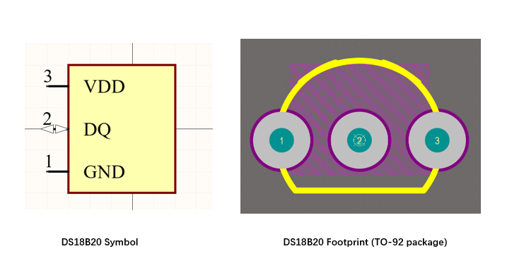
DS18B20 Symbol, Footprint, and 3D STEP Model
For IoT and hardware design engineers, the DS18B20 symbol, footprint, and 3D model are important because they need to be integrated into PCB design applications. Below is the production-ready symbol, footprint, and STEP 3D model is available which you can download and use directly in your design application.
Understanding One-Wire Communication Protocol
One wire communication protocol was originally developed by Dallas Semiconductor. It is a low-speed and half-duplex serial communication system and is mainly used in digital devices such as the DS18B20 temperature sensor.
Half-duplex is a serial communication protocol where data can flow in both directions, but only one direction at a time. This method uses a single wire for both reception and transmission, therefore reducing the wiring complexity and overall system cost. The DS18B20 temperature sensor uses this communication protocol to enable communication via a single data line plus ground.
What is One Wire Protocol?
One wire protocol is a basic serial communication protocol that is mostly used in devices of consumer electronics, IoT devices, and medical devices with a microcontroller for the transmission and reception of data over a single shared bus called a MicroLAN for identification, authentication, and data logging, etc.
The one-wire protocol works on the master-slave concept, i.e., a single microcontroller acts as a master and controls the bus, and one or more slave devices, such as a DS18B20 temperature sensor, respond to the master commands. The communication happens on a one-way data line known as DQ with an external pull-up resistor.
Unlike I2C and SPI, the one-wire communication protocol does not require a clock line and allows multiple sensors on one data wire.
One Wire Bus Hardware Configuration
The 1-wire bus is a single data line protocol, and it works on the master slave concept as we know so far. 1-wire uses an open-drain architecture, which means that devices can only pull the bus low. This allows each device to “release” the data line when the device is not transmitting data, so the bus is available for use by another device. So, the DQ pin of DS18B20 is open-drain with an external circuit as shown in the figure below.
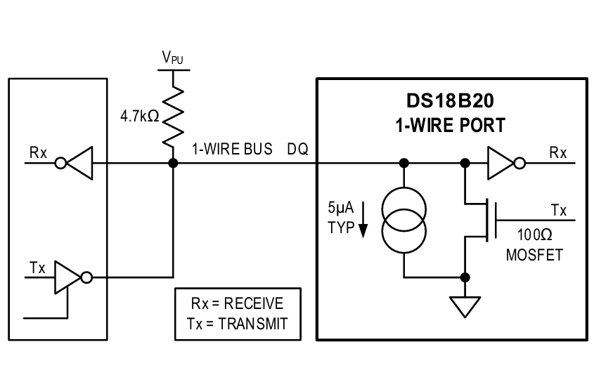
The idle state of the 1-wire protocol is high, and therefore, this protocol requires an external pull-up resistor of 4.7kΩ. If a transaction needs to be suspended, the bus must be left in the idle state if the transaction is to resume. Moreover, If the bus is held low for more than 480µs, all components on the bus will be reset.
Powering the DS18B20 Temperature Sensor via One Wire
Another useful feature of the 1-wire protocol is its parasitic power mode. In this mode, the VDD is connected with the GND, and a sensor like DS18B20 draws power from the DQ line when it is high. However, this mode requires a strong pull resistor during the temperature conversion.
One-Wire Communication and Command Operation
To access the DS18B20 sensor over a one-wire protocol, the three-step sequence must be followed: initialization, ROM command (device selection), and function command (sensor operation).
Step 1 : Initialization
In the first step, the master transmits a reset pulse, i.e., pulling the DQ bus low for at least 480us, and then releases it. Now, if there is any device such as DS18B20 present, it must respond with a presence pulse, i.e., pulling the DQ line low for at least 60us. This confirms the presence and indicates that the communication is possible.
Step 2: ROM Commands (Device Selection)
Once the sensor presence pulse is detected, the master, such as the STM32 microcontroller, issues a one-wire ROM command, which is used to address the device on the bus. The commands which are commonly used are;
DS18B20 ROM Commands
Step 3: Function Command (DS18B20 Operation)
Now, as the device has been selected and addressed via a ROM command. The master (likely the microcontroller) issues a function-specific command to control the sensor operation, such as;
DS18B20 Function Commands
DS18B20 64-Bit Lasered ROM Code
Each DS18B20 digital temperature sensor comes with a unique 64-bit code, which is stored in ROM. The 8 LSBs contain the 1-wire family code of DS18B20. The next 48 bits contain the unique serial number. The next 8 MSBs consist of a cyclic redundancy check (CRC).
DS18B20 64-bit ROM Code Structure
DS18B20 Wiring Guide: Schematics and Cable Considerations
This digital temperature sensor provides an accurate temperature measurement and stable communication. However, incorrect wiring, improper pull-up resistor selection, and incorrect power mode can lead to incorrect temperature readings and failures. This section will help you understand the wiring and schematics guide with DS18B20.
Standard Power Mode Wiring Connection of DS18B20
In the standard power connection mode, the DS18B20 temperature sensor VDD is connected with the 3.3 or 5V, GND with the system Ground, and DQ pin with the GPIO pin of arduino. Additionally, always use the 4.7 kΩ pull-up resistor between DQ and VDD as shown in figure below.

Parasatic Power Mode Wiring Connection of DS18B20
In parasitic power mode connection of DS18B20, connect the VDD (pin 3) with the GND, DQ (pin 2) with the GPIO of the microcontroller or Arduino and GND with the system GND. It is worth noting that in parasatic mode, the waterproof temperature sensor draws the power directly from the DQ bus when it is high. The wiring and schematic of parasatic mode of DS18B20 with the Arduino is shown figure below.

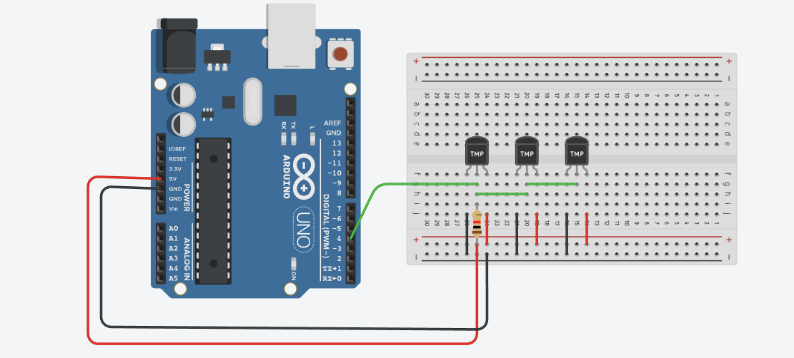
Multi-Sensor Wiring on a Single Bus
To connect or interface multiple DS18B20 sensors on a single bus, connect all VDD pins to 5V and all GND pins to GND. Also, connect all Data (DQ) pins in parallel to a single microcontroller GPIO pin as shown in the figure below. Also, connect a 4.7kΩ pull-up resistor from the Data line to VDD for reliable communication.
Cable Length and Signal Integrity Considerations
The DS18B20 digital temperature sensor also comes as waterproof probes. The pin configuration will remain the same, i.e., three pins: GND, VDD, and DQ (data line bus). When using the DS18B20 as a waterproof probe, use twisted pair cables (DQ + GND), minimize the stubs, and place a strong pull-up resistor close to the master. Also, avoid running the sensor cables parallel to high voltage lines.

Measuring Operation of DS18B20
The DS18B20 digital temperature sensor measures the temperature using its silicon-based temperature sensing element and with an Analog to Digital converter (ADC). Analog temperature sensors output a voltage that is proportional to the temperature. However, the DS18B20 internally performs signal conditioning, digitization, and results in a direct digital temperature data over a one-wire interface.
Temperature Conversion Process
The DS18B20 starts the temperature measurement when the convert T command (44h) is issued over the one-wire bus. The measurement process follows a strict sequence, which goes;
DS18B20 Temperature Conversion Sequence
The DS18B20 also supports a programmable resolution, which means that the designers can choose between speed and precision.
DS18B20 Resolution and Conversion Time
DS18B20 Interfacing With Microcontrollers and Example Codes
The DS18B20 is popular due to its simple integration configuration with a wide range of microcontrollers and embedded platforms such as the STM32 microcontroller, ESP32, and Arduino UNO. Unlike other digital temperature sensors, the wire interface of DS18B20 does not require any ADCs or external peripherals. Moreover, it allows the microcontroller to read the temperature data using a single GPIO pin.
The DS18B20 temperature sensor follows the general interface regardless of the microcontroller or embedded platform used. The general interfacing of DS18B20 with the microcontrollers follows;
- Configure a GPIO pin as open-drain or bidirectional
- Add a 4.7 kΩ pull-up resistor between DQ and VDD
- Send a reset pulse and wait for presence detection
- Select the sensor using a ROM command
- Start temperature measurement using Convert T (44h)
- Wait for conversion to complete
- Read temperature data using Read Scratchpad (BEh)
- Verify data integrity using CRC
Interfacing DS18B20 With Arduino
The Arduino is the most common embedded platform used with the DS18B20 temperature sensor for measuring the temperature. The typical connection of DS18B20 with the Arduino is: Connect the VDD pin with 3.3 or 5V, the GND pin with the Arduino GND, and the DQ data line bus with the digital GPIO pin of Arduino, e.g., GPIO 4 of Arduino.
The example Arduino code below demonstrates the DS18B20 interfacing with one-wire initialization, temperature conversion, and scratchpad reading.
#include <OneWire.h>
#include <DallasTemperature.h>

#define ONE_WIRE_BUS 4

OneWire oneWire(ONE_WIRE_BUS);
DallasTemperature sensors(&oneWire);

void setup() {
  Serial.begin(9600);
  sensors.begin();
}

void loop() {
  sensors.requestTemperatures();
  float tempC = sensors.getTempCByIndex(0);
  Serial.print("Temperature: ");
  Serial.print(tempC);
  Serial.println(" °C");
  delay(1000);
}
Interfacing DS18B20 With ESP32
The connection or interfacing of DS18B20 with the ESP32 follows the exact procedure we have discussed in the Arduino board. Connect the +5V or 3.3V with the VDD pin of DS18B20, the GND pin with the ESP32 GND, and the DQ data bus pin with the GPIO pin, e.g., pin 4 of the ESP32 controller.
So, the example ESP32 code below demonstrates the DS18B20 interfacing with one-wire initialization, temperature conversion, and scratchpad reading.
#include <OneWire.h>
#include <DallasTemperature.h>

#define ONE_WIRE_BUS 4

OneWire oneWire(ONE_WIRE_BUS);
DallasTemperature sensors(&oneWire);

void setup() {
  Serial.begin(115200);
  sensors.begin();
}

void loop() {
  sensors.requestTemperatures();
  float tempC = sensors.getTempCByIndex(0);
  Serial.printf("Temperature: %.2f °C\n", tempC);
  delay(2000);
}
DS18B20 Digital Temperature Sensor Simulation with Arduino
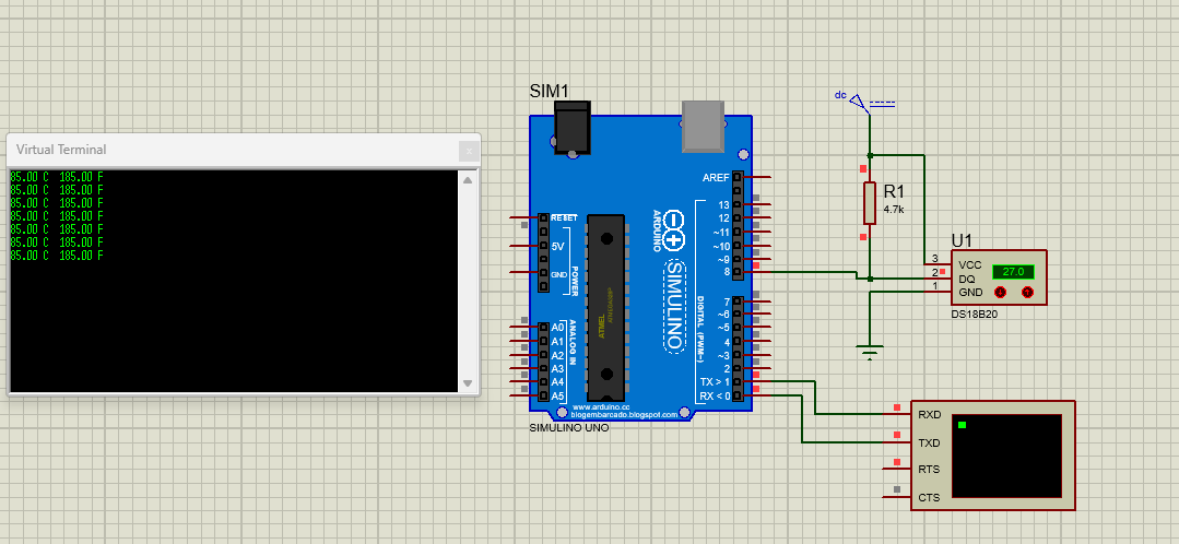
In this section, I have used Proteus software to demonstrate the working simulation of the DS18B20 temperature sensor with the Arduino. The Arduino code shows communication behavior, temperature conversion, and data handling without risking physical components.
The Arduino board acts as the one-wire master, and the DS18B20 sensor is connected to the single digital GPIO pin 8. A 4.7kΩ pull-up resistor is placed between DQ and VDD. Finally, the temperature data is shown using the serial monitor or virtual terminal.
#include <OneWire.h>
#include <DallasTemperature.h>
#define ONE_WIRE_BUS 8

OneWire oneWire(ONE_WIRE_BUS);
DallasTemperature sensors(&oneWire);

float Celsius = 0;
float Fahrenheit = 0;

void setup() {
  sensors.begin();
  Serial.begin(9600);
}

void loop() {
  sensors.requestTemperatures();

  Celsius = sensors.getTempCByIndex(0);
  Fahrenheit = sensors.toFahrenheit(Celsius);

  if(Celsius> -127){
  Serial.print(Celsius);
  Serial.print(" C  ");
  Serial.print(Fahrenheit);
  Serial.println(" F");

  delay(1000);
}
}
DS18B20 vs Alternatives (NTC, PT100, DHT22, TMP36, TMP117)
Choosing the right temperature sensor depends on accuracy requirements, operating environment, wiring complexity, cost, and system scalability. While the DS18B20 waterproof digital temperature sensor is a popular choice for many industrial and IoT applications, it is not always the best solution for every use case. There are many other temperature sensors, such as NTC thermistor, PT100, DHT22, TMP36, and TMP117 are available, and using any of them is entirely based on the design requirement and specifications.
Comprehensive Comparison of DS18B20 and Alternative Temperature Sensors
Conclusion
To wrap up, the DS18B20 waterproof digital temperature sensor is one of the most popular temperature sensors among all due to its ease of integration, minimum external peripherals requirements, and no requirement for ADC calibration. This sensor has a one-wire communication, which means that it has only one DQ data line bus for both transmission and reception, making it ideal for applications where minimum wiring is required.
Compared to analog sensors and high-precision RTDs, the DS18B20 strikes an excellent balance between accuracy, cost, scalability, and ease of integration. While alternatives such as PT100 or TMP117 may be preferable in ultra-precision environments, the DS18B20 continues to excel in distributed sensing systems, Industrial IoT deployments, HVAC systems, energy storage, and smart agriculture.
Frequently Asked Questions (FAQ)
All DS18B20 sensors can share one One-Wire bus. Therefore connect;
All DQ pins together
All GND pins together
All VDD pins together (if using external power mode) and ne 4.7 kΩ pull-up resistor between DQ and VDD pin.
Typical accuracy: ±0.5 °C from –10 °C to +85 °C
Maximum error across full range: ±2 °C
Yes, the waterproof stainless steel probe variant is fully submersible and resistant to corrosion. It is ideal for water tanks, industrial fluids, and environmental monitoring. Ensure the cable and sealing are intact for long-term reliability.
Typical practical length: 30–100 meters, and it also depends on cable type, pull-up resistor, and the number of sensors. Use twisted-pair cables for DQ + GND and avoid star topologies for stable communication
Use 12-bit resolution for maximum precision and calibrate the sensor with a known reference thermometer
The stainless steel waterproof probe is slightly slower due to thermal mass. Typical conversion times are;
9-bit: 93.75 ms
12-bit: 750 ms