Modern electronics keep getting thinner, lighter, and more compact. As device sizes shrink, the need for low-profile interconnects becomes even more important. That is where the FFC connector comes in.
In real-world electronics design, engineers rely on compact, reliable interconnects to meet both mechanical and electrical constraints.
An FFC connector, also called a flat flexible cable connector, is designed to connect thin, flat cable assemblies to a PCB without taking up the space that traditional wire harnesses require.
You will find FFC connectors in laptops, printers, automotive displays, cameras, medical devices, industrial control systems, and embedded hardware.
These connectors matter because they make it possible to route signals through tight mechanical spaces while keeping assembly efficient and reliable.
In many designs, choosing the right FFC cable connector affects not only fit, but also serviceability, durability, signal stability, and production yield.
You will also often see FFC discussed alongside FPC. Although the two are related, they are not the same. We will break down the differences between an FFC vs FPC connector so you can choose the right option for your design.
What Is an FFC Connector?
An FFC connector is a compact electrical connector used to connect flat flexible cables (FFC) to printed circuit boards, enabling reliable signal transmission in space-constrained electronic devices.
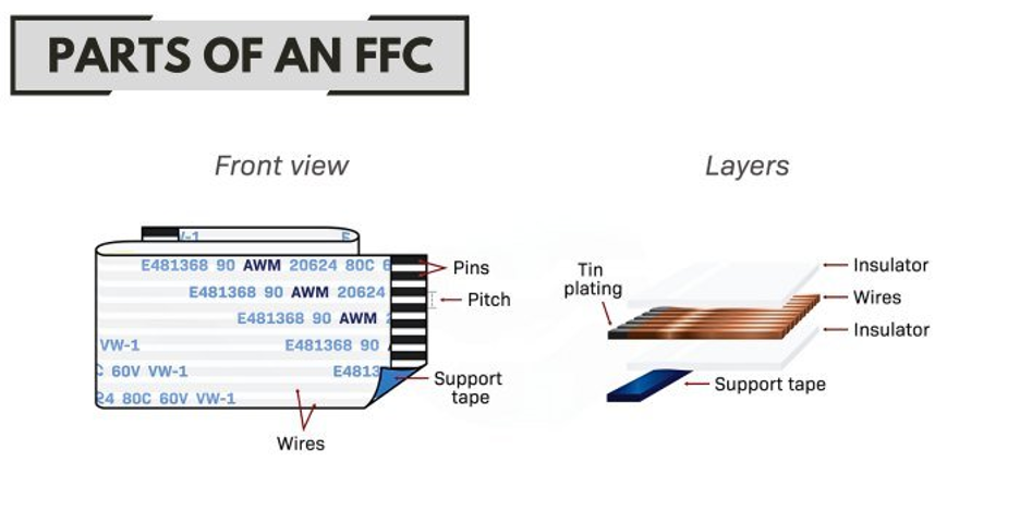
The cable itself contains multiple flat conductors arranged in parallel and laminated between insulating films.
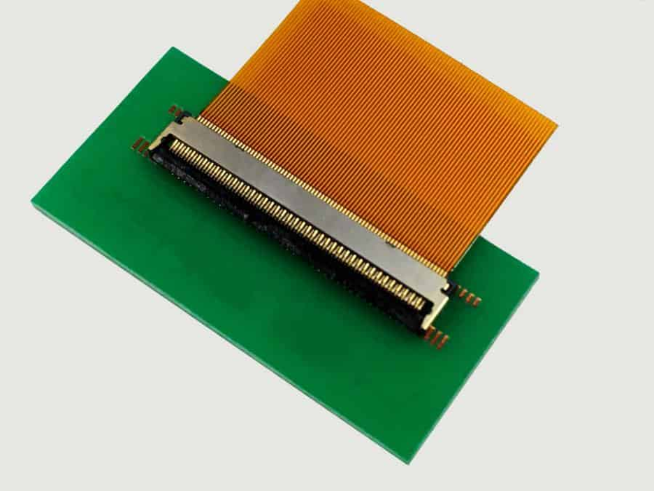
The connector aligns these exposed conductors with matching metal contacts on a PCB, creating a stable electrical path in a very small footprint.
In simple terms, an FFC connector gives a thin flat cable a safe, precise, and repeatable way to connect to a circuit board.
It replaces bulky wire harnesses with a cleaner, low-profile interconnect solution that fits modern compact designs.
Most ffc connectors use a slot-based insertion design. The cable slides into the connector until it reaches a defined stop point, ensuring proper alignment between the cable conductors and connector terminals.
Once inserted:
- A latch, slider, or friction mechanism secures the cable
- Internal contacts press against the exposed conductors
- Electrical signals flow between the cable and PCB
Contact pressure plays a critical role here.
- Too little pressure → intermittent signals or unreliable connections
- Too much pressure → cable damage or reduced connector lifespan
That is why parameters like pitch, cable thickness, and locking style must match exactly. Even small mismatches can lead to connection failures in real-world applications.
For different application requirements, Flywing Tech also provides a range of FFC/FPC connector contacts and connector housings, making it easier to match the right connector to your cable and PCB design.
Main Parts of an FFC Connector
Understanding the internal structure helps when selecting or troubleshooting an ffc cable connector.
Contacts (Terminals)
These are the conductive metal elements inside the connector. They directly touch the exposed traces on the FFC cable and carry signals to the PCB.
Housing
The durable molded plastic typically makes the housing. It holds the contacts in place, guides the cable during insertion, and ensures proper alignment.
Locking Mechanism
Depending on the connector type, this may include:
- Flip-lock (hinged latch)
- Slide-lock (moving actuator)
- Friction-fit (no separate latch)
This mechanism secures the cable and maintains consistent contact pressure over time.
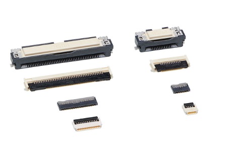
FFC Connector Types and Configurations
There is no single “standard” ffc connector that fits every design. In practice, three key factors determine the selection of ffc connectors.
- Locking mechanism
- Contact orientation
- Mounting style
Choosing the wrong type can lead to assembly issues, poor contact reliability, or even complete signal failure even if the pin count looks correct.
That is why understanding these variations is critical when selecting an ffc cable connector.
By Locking Mechanism
The locking mechanism determines how the cable is inserted, secured, and maintained under contact pressure. This directly affects assembly reliability and long-term performance.
ZIF (Zero Insertion Force)
A ZIF ffc connector allows the cable to slide into the connector with almost no resistance. A latch (usually flip or slide type) secures the cable once it is fully inserted.
We use it to:
- Minimize risk of damaging fine-pitch cables
- Ensure consistent contact pressure
- Ideal for high-density and delicate assemblies
Because of these advantages, ZIF is the most common type of ffc connector in laptops, displays, and embedded electronics.
LIF (Low Insertion Force)
A Low Insertion Force (LIF) connector also allows relatively easy cable insertion, but without a fully independent locking latch like ZIF.
Key characteristics:
- Slight resistance during insertion
- Relies partially on terminal tension
- May include simple retention features
LIF connectors are less common than ZIF today but still appear in designs where controlled insertion and moderate retention are acceptable.
Non-ZIF (Friction Lock)
Non-ZIF connectors rely on friction and terminal spring force to hold the cable in place. There is no separate latch mechanism.
Advantages:
- Simpler design
- Lower cost in some cases
- Fewer moving parts
Limitations:
- Higher risk of cable damage during insertion
- Less suitable for repeated servicing
- More sensitive to insertion alignment
Engineers use these connectors in laptops, printers, and displays.
By Contact Orientation
Contact orientation defines which side of the cable carries the exposed conductors and how the connector engages them. This is one of the most common sources of mismatch in ffc connectors.
Top Contact
In a top-contact ffc connector, the internal terminals press against the top side of the cable’s exposed conductors. When the cable’s conductive pads face upward during insertion.
Bottom Contact
In a bottom-contact design, the terminals engage the underside of the cable. Even if you select the correct pitch and pin count (e.g., 20 pin ffc connector), the connection will fail if the contact side is wrong.
Dual Contact
Some advanced ffc cable connectors support both orientations or provide more flexible mating options.
Where they are useful:
- Complex routing paths
- Multi-variant product designs
- Situations require cable flipping when needed.
By Mounting Style
The mounting style determines how the connector attaches to the PCB, affecting mechanical strength and the manufacturing process.
Surface-Mount (SMT)
SMT ffc connectors are soldered directly onto the surface of the PCB. Why they dominate modern designs:
- Enable low-profile layouts
- Compatible with automated assembly
- Ideal for compact consumer electronics
Most modern ffc connectors used in laptops, displays, and IoT devices are SMT-based.
Through-Hole
Through-hole connectors pass pins through the PCB and solder them on the opposite side.
Advantages:
- Stronger mechanical anchoring
- Better resistance to vibration and mechanical stress
Typical use cases:
- Industrial equipment
- Automotive electronics
- Ruggedized systems
Although less common in ultra-thin devices, through-hole ffc connectors remain important where durability is a priority.
FFC Connector Pin Configurations and Pitch
When searching for an ffc connector, most buyers start with pin count. That is why terms like 20 pin ffc connector, 12 pin ffc connector, and 22 pin ffc connector are so common.
Pin count alone is never enough. In practice, pitch is just as important.
Pitch is the center-to-center distance between adjacent contacts in the connector (and cable). It determines how closely spaced the conductors are.

Common pitch values in ffc connectors include:
- 0.5 mm → high-density, compact electronics
- 1.0 mm → more robust, easier handling
- Other variations depending on application
In practice, pitch mismatches are one of the most common causes of failed connections. Even experienced engineers can overlook this when sourcing replacement parts or working across different suppliers.
Common Pin Counts in FFC Connectors
Different applications require different numbers of signal lines, which is why you will see multiple pin configurations in the market.
12-Pin FFC Connector
A 12 pin ffc connector typically serves in the following:
- small display modules
- sensor interfaces
- compact embedded boards
- control panels with limited I/O
These connectors are ideal when space is tight and only a modest number of signals are needed.
You may also see variants labeled as:
- connector ffc fpc 12pin
- ffc fpc 12pin connector
These usually indicate compatibility with both FFC and FPC cables, but always verify specifications before assuming interchangeability.
20-Pin FFC Connector
A 20 pin ffc connector is one of the most commonly used configurations.
Typical applications include:
- display panels and LCD modules
- printers and scanners
- camera modules
- embedded systems requiring mixed signal and power lines
This configuration offers a good balance between size and functionality, making it popular in both consumer and industrial electronics.
22-Pin FFC Connector
A 22 pin ffc connector (or ffc fpc connector 22pin) is often used in:
- touch/display assemblies
- compact computing devices
- OEM replacement parts
- tightly integrated modules
The slightly higher pin count allows additional signal lines without significantly increasing connector size.
FFC Cable Specifications
Selecting the right ffc connector always starts with understanding the cable. In practice, many connection issues come from mismatched ffc cable specifications rather than the connector itself.
An FFC cable may look simple, but several parameters determine whether it will fit correctly, carry signals reliably, and last over time.
These include construction, pitch, thickness, flexibility, shielding, and environmental limits. Even if you choose the correct ffc cable connector, a mismatch in any of these can lead to failure.
Cable Construction and Materials
Manufacturers build FFC cables using flat conductors laminated between insulating films. The exposed pads at each end can mate directly with the connector contacts.
While the structure is straightforward, quality and consistency matter. Variations in conductor material, insulation, and bonding can affect durability and long-term reliability.
Pitch and Conductor Spacing
Pitch defines the spacing between adjacent conductors. Common values include:
- 0.5 mm → high-density, compact electronics
- 1.0 mm → easier handling, more robust connections
The cable and connector must match exactly. Even a small mismatch will prevent proper alignment of contacts, regardless of pin count.
Most manufacturers such as Molex, Hirose, and TE Connectivity define strict tolerances for pitch, cable thickness, and contact alignment. Always refer to the connector datasheet to confirm compatibility.
Thickness and Fit Compatibility
Cable thickness directly affects how the cable sits inside the connector and how much pressure is applied by the terminals.
- Too thin → weak or intermittent contact
- Too thick → difficult insertion or connector damage
This is a common issue when mixing cables and connectors from different sources, so always verify thickness against the connector datasheet.
Flexibility, Bend Radius, and Routing
Not all ffc cables are designed for the same mechanical conditions.
- Static applications → cable remains fixed after installation
- Dynamic applications → cable bends repeatedly
For moving assemblies, check bend radius and flex cycle rating. Poor routing, sharp bends, or stress near the connector can significantly reduce lifespan.
Cable length also plays a role. Longer cables are more prone to noise and mechanical strain, especially in compact or high-density layouts.
If you are evaluating different cable types, you can explore Flywing Tech’s range of flat flexible cables and assemblies.
Contact Orientation and Shielding Considerations
One of the most critical aspects of ffc cable selection is contact orientation.
A Type A FFC cable has exposed conductors on the same side at both ends. This makes it suitable for straight-through connections where both connectors face the same direction.
It is commonly used in displays, printers, and simple PCB layouts because it simplifies routing.
A Type B FFC cable has exposed conductors on opposite sides at each end.
This allows the cable to flip orientation without twisting, making it ideal for compact designs where connectors face opposite directions or require folded routing paths.
Shielding and Signal Integrity
Most ffc cables are unshielded, which works well for short internal connections in consumer electronics, displays, printers, and embedded systems.
However, shielding becomes important in more demanding environments, such as:
- high-speed signal transmission
- EMI-sensitive circuits
- industrial or automotive systems
- longer cable runs
Engineers use shielded cables in high-noise environments but they may increase cost, reduce flexibility, and affect thickness.
FFC vs FPC Connectors
The terms FFC connector and FPC connector are often used interchangeably, but they refer to two different cable technologies.
An FFC (Flat Flexible Cable) is a simple laminated cable made of parallel conductors. It is cost-effective and ideal for straight or gently bent connections.
An FPC (Flexible Printed Circuit) is a more advanced structure. It uses etched copper traces on a flexible substrate (usually polyimide), similar to a PCB but bendable.
Because of this, an fpc ffc connector may physically accept both types, but the performance and design flexibility differ significantly.

Let’s look at the differences in more detail:
Material and Construction Differences
FFC cables use flat copper conductors laminated between plastic films. This makes them simple, uniform, and easy to manufacture in standard lengths.
FPC cables, on the other hand, are engineered circuits. They can include:
- Complex trace routing
- Variable widths
- Multilayer designs
- Integrated components (in some cases)
This makes FPC more versatile but also more complex and expensive.
Flexibility and Durability
Both FFC and FPC are flexible, but they behave differently in real-world conditions.
- FFC cables are best suited for static or low-movement applications
- FPC cables handle dynamic bending and tighter routing more effectively
If your design involves frequent movement, tight folds, or repeated flex cycles, FPC is usually the better choice.
Cost Comparison
Cost is one of the biggest deciding factors in the ffc vs fpc connector decision.
- FFC solutions are generally more affordable
- FPC solutions cost more due to manufacturing complexity
For high-volume consumer products where margins matter, FFC is often preferred unless FPC capabilities are required.
| Feature | FFC | FPC |
| Structure | Parallel flat conductors laminated in film | Printed copper traces on flexible substrate |
| Design complexity | Simple | Highly customizable |
| Cost | Lower | Higher |
| Flex performance | Limited dynamic bending | Excellent for repeated flexing |
| Routing capability | Straight or simple bends | Complex routing possible |
| Typical applications | Displays, printers, laptops | Smartphones, compact electronics |
| Connector compatibility | Works with standard ffc connector | Requires compatible fpc/ffc connector |
If your priority is cost, simplicity, and standard interconnects, go with an ffc connector.
If your design requires tight routing, high flexibility, or compact circuit integration, an fpc connector is the better option.
In real engineering workflows, the choice is rarely about “which is better.” It is about which one fits the mechanical design, electrical requirements, and production constraints.
Common Applications of FFC Connectors
One reason ffc connectors are so widely used is that they solve both space and assembly challenges across many industries.
Consumer Electronics
Laptops, printers, cameras, scanners, TVs, and display modules commonly use an ffc cable connector to connect internal boards, displays, keypads, or sensor assemblies.
These products benefit from thin cable routing, repeatable assembly, and low-profile connector designs.
Automotive Systems
In automotive electronics, FFC assemblies may appear in infotainment modules, instrument clusters, and compact control systems.
Automotive use requires more attention to vibration, temperature range, and long-term reliability than a typical consumer device.
Industrial Equipment
Industrial HMIs, printers, measurement equipment, and compact controllers may use ffc connectors when internal board-to-board or board-to-panel connections need clean routing.
In these settings, contamination, mechanical stress, and maintenance access should be considered early.
Embedded Systems and IoT
Embedded engineers often use flat cable interconnects for displays, camera modules, small peripheral boards, and compact enclosures.
In prototypes and production systems alike, the correct ffc connector can simplify the mechanical design significantly.
How to Install an FFC Connector (Step-by-Step)
Proper installation is one of the biggest factors in connection reliability. Even a high-quality connector will fail if the cable is inserted incorrectly.
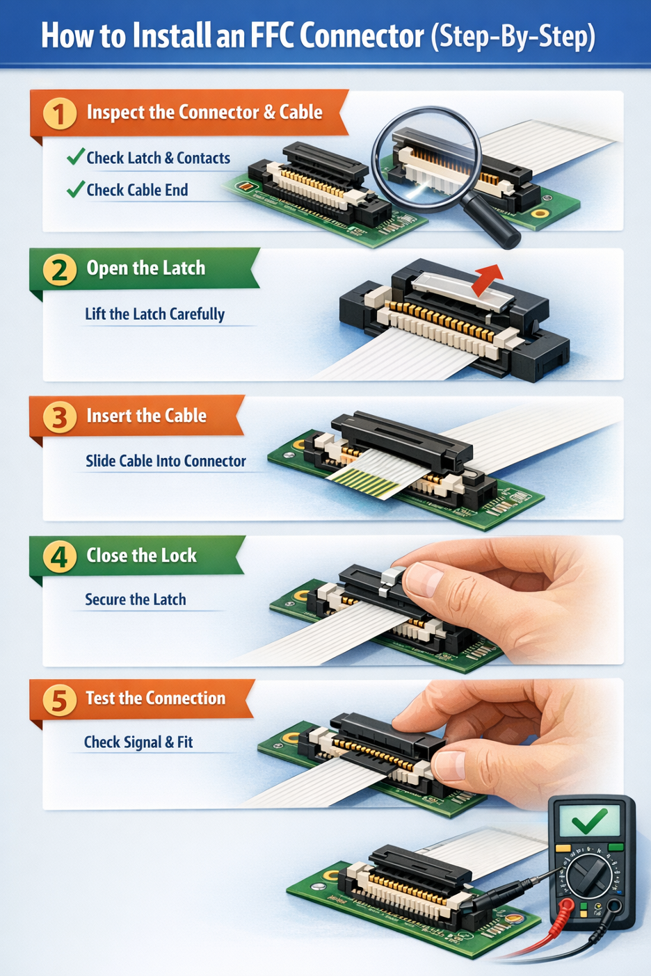
Step 1: Inspect the Connector and Cable
Check that the latch is undamaged, the contacts are clean, and the cable end is not creased or contaminated.
Step 2: Open the Latch
If the connector is ZIF or slider-based, gently open the latch according to the part design. Do not force it. These locking parts are small and can crack if handled carelessly.
Step 3: Insert the Cable
Slide the FFC cable straight into the connector until it reaches the specified stop position. The exposed contacts must face the correct direction for the connector type.
Step 4: Close the Locking Mechanism
Close the latch or secure the locking bar evenly. Avoid twisting or pressing down only on one side.
Step 5: Test the Connection
After assembly, verify that the cable is seated evenly and does not slip out. Functional testing should confirm signal continuity and stable operation.
Common Installation Mistakes
Incorrect orientation
This is one of the most common issues. If the cable contacts face the wrong side, the circuit may not work at all.
Forcing insertion
If the cable does not slide in smoothly, stop and recheck pitch, thickness, and latch position.
Damaging contacts
Repeated improper insertion can deform the connector terminals or wear the cable end.
FFC Connector vs Ribbon Cable Connectors
Although both involve multiple conductors arranged in parallel, an ffc connector is not the same as a ribbon cable connector.
Structural Differences
An FFC is a flat laminated cable with thin parallel conductors. Traditional ribbon cable usually consists of multiple insulated round or flat wires joined side by side.
The connector systems are different because the cable constructions are different.
Use Cases
FFC is ideal for compact internal electronics where space is limited. Ribbon cable is more common in older internal computer wiring, IDC-based systems, and applications where bulkier multi-wire assemblies are acceptable.
Performance Comparison
FFC offers a cleaner low-profile solution. Ribbon cable can be easier to terminate in some legacy or bench applications, but it typically takes more space.
If your design is compact, thin, or mechanically constrained, ffc connectors usually make more sense than ribbon cable connectors.
Final Thoughts
An FFC connector may look like a small component, but it plays a critical role in modern electronics design. The right selection improves assembly efficiency, ensures signal reliability, and supports long-term product performance.
In real-world applications, engineers evaluate more than just pin count. Pitch, cable type, contact orientation, thickness, and environmental conditions must all align for a reliable connection.
The safest approach is always the same: verify datasheets, validate compatibility, and select components based on actual design requirements rather than assumptions.
Taking the time to get these details right early can prevent costly redesigns, debugging issues, and field failures later.
When selecting components, it is important to choose suppliers that provide consistent quality and clear specifications. Flywing Tech offers a wide selection of FFC connectors, cables, and accessories suitable for embedded systems, industrial electronics, and OEM applications.
Frequently Asked Questions
What is an FFC connector?
An FFC connector is a compact electrical connector used to connect flat flexible cables to PCBs in compact electronic devices.
What is the difference between FFC and FPC connectors?
FFC uses flat laminated cables, while FPC uses printed flexible circuits with more complex routing.
What is a ZIF FFC connector?
A ZIF FFC connector allows easy cable insertion with minimal force and uses a latch to secure the connection.
How do I choose an FFC connector?
Choose based on pitch, pin count, cable type, orientation, and application requirements.
What is an FFC connector used for?
An FFC connector is used to connect a flat flexible cable to a PCB. It is commonly found in displays, printers, laptops, cameras, industrial controls, and compact embedded systems.
Are FFC and FPC interchangeable?
Not always. Some connectors are marketed as fpc ffc connector types because they support both cable forms, but interchangeability depends on pitch, thickness, contact orientation, and connector design.
How do I know my FFC pitch?
Pitch is the spacing between adjacent conductors. The safest way to confirm it is from the cable drawing, connector datasheet, or precise measurement using proper tools. Guessing can lead to mismatched parts.
Can FFC cables be reused?
Sometimes, yes. But repeated insertion can wear the cable end or damage the latch if the assembly is not designed for frequent servicing. Always inspect the exposed contacts before reuse.
What is the difference between a 12 pin, 20 pin, and 22 pin FFC connector?
The main difference is the number of electrical positions. A 12 pin ffc connector, 20 pin ffc connector, and 22 pin ffc connector serve different signal-count requirements, but each still must match the correct pitch, thickness, and orientation.the application.
COMMENTS