In modern embedded systems, firmware size and functionality continue to grow. Microcontrollers often include internal flash memory, but in many designs this storage quickly becomes insufficient. As a result, engineers frequently rely on external flash memory for microcontrollers to store firmware images, bootloader data, configuration parameters, and update packages. Among the most widely used solutions is the W25Q32 Flash Memory, a 32-Mbit SPI NOR flash device known for its reliability, fast read speeds, and simple interface.
The W25Q32 SPI Flash is commonly integrated into embedded platforms such as IoT devices, industrial controllers, consumer electronics, and development boards. Because it communicates through a standard SPI interface, it can easily connect to a wide range of microcontrollers, including STM32, ESP32, and Nordic devices. This flexibility makes it a practical choice for SPI flash firmware storage, especially when systems need to support bootloaders, firmware updates, and secure data storage.
This guide provides a comprehensive overview of the W25Q32 Flash Memory, focusing on its role in bootloaders, firmware update mechanisms, and common failure scenarios.
Overview of W25Q32 SPI Flash Memory
The W25Q32 SPI Flash Memory is a 32-Mbit (4 MB) serial NOR flash device widely used in embedded systems for code storage, firmware updates, and data logging. It belongs to the Winbond W25Q series, which is known for its high reliability, fast read performance, and low pin-count SPI interface. Therefore, making it ideal for space- and cost-constrained designs.
Unlike parallel flash, the W25Q32 SPI Flash communicates using the Serial Peripheral Interface (SPI), requiring only a few pins to operate. This simplifies PCB design while still delivering sufficient speed for most embedded applications.
Key Specifications
| Parameter | Specification | Description |
|---|---|---|
| Memory Capacity | 32 Mbit (4 MB) | Total storage available for firmware, data, and bootloader |
| Interface | SPI / Dual SPI / Quad SPI (QSPI) | Supports multiple communication modes for speed optimization |
| Operating Voltage | 2.7V – 3.6V | Compatible with standard 3.3V microcontroller systems |
| Max Clock Frequency | Up to ~104 MHz | Determines maximum data transfer speed |
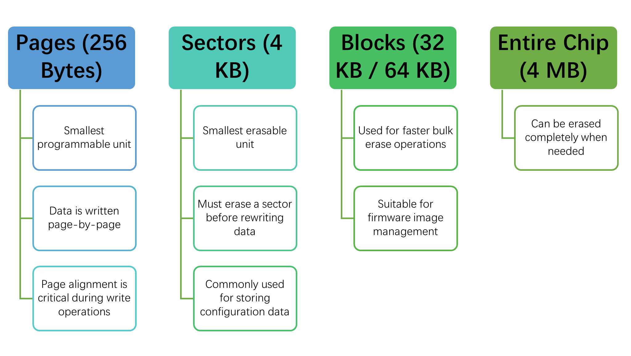
| Page Size | 256 Bytes | Smallest programmable unit |
| Sector Size | 4 KB | Smallest erasable unit |
| Block Size | 32 KB / 64 KB | Used for faster bulk erase operations |
| Erase Types | Sector, Block, Chip Erase | Flexible erase options depending on application needs |
| Endurance | ~100,000 Program/Erase Cycles | Indicates flash lifespan under repeated writes |
| Data Retention | Up to 20 Years | Duration data can be stored without power |
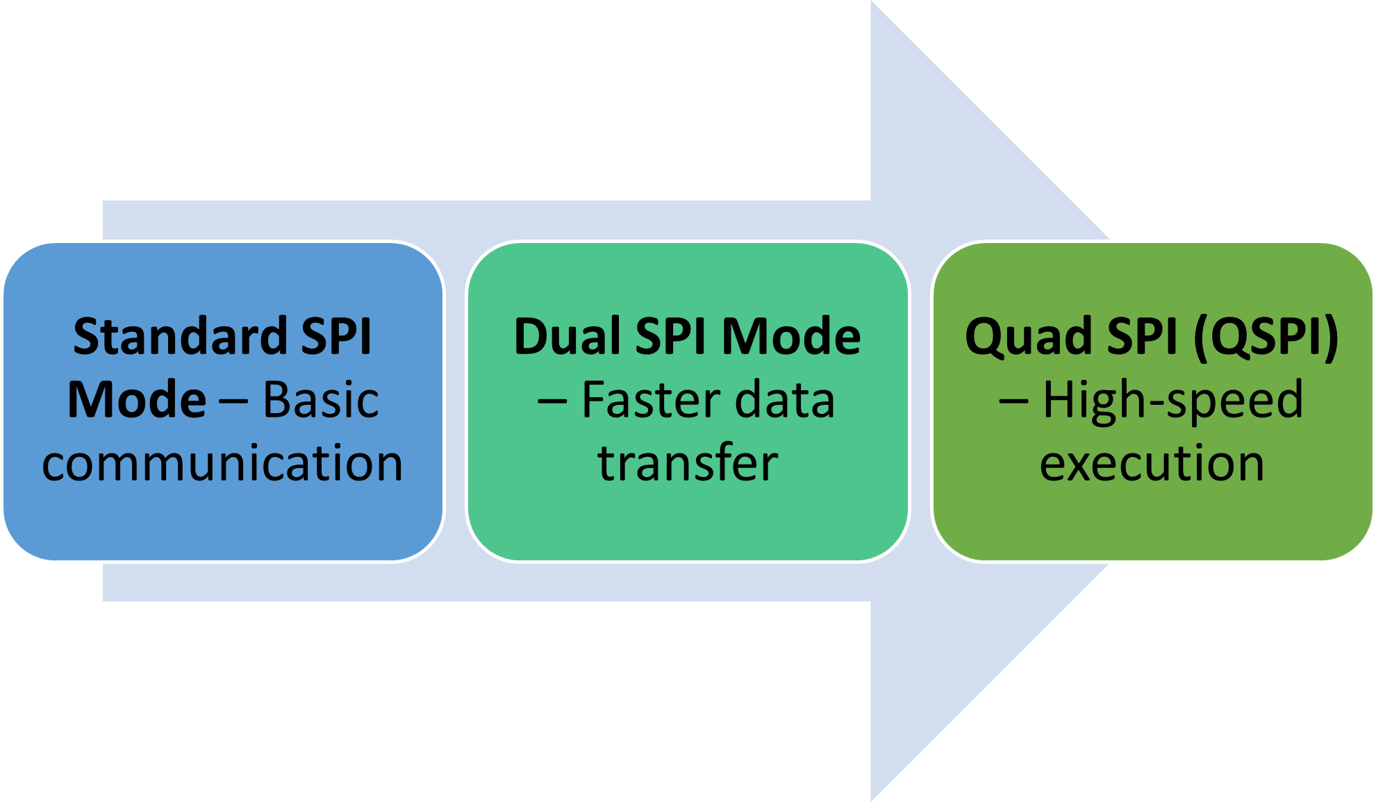
| Read Modes | Standard, Dual, Quad SPI | Enables faster read operations in advanced modes |
| Package Options | SOIC, WSON, USON | Available in compact packages for different PCB designs |
Internal Memory Architecture
The internal structure of the W25Q32 SPI Flash is organized hierarchically, which directly impacts how firmware and data should be stored:
Performance Modes
The W25Q32 SPI Flash supports multiple read modes:
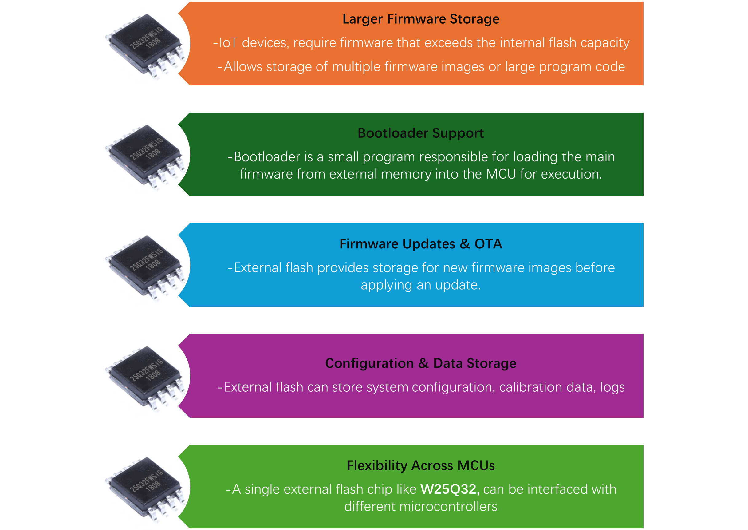
Why Embedded Systems Use External Flash Memory
In many embedded systems, the internal flash memory of a microcontroller is often limited in size. As applications grow more complex, the need for larger firmware, multiple features, and secure boot mechanisms and internal memory alone may not be sufficient. This is where external flash memory for microcontrollers, like the W25Q32 SPI Flash, becomes essential.
Key Reasons for Using External Flash
When designing the embedded system, one often requires using the flash memory to store data such as sensor data, like BIM270, for gesture recognition and step counting in wearable and hearable devices. Similarly, for storing the data of the BMI150 sensor, which is used to measure accurate absolute orientation, electronic compassing, and navigation in mobile devices, drones, and IoT applications. Similarly, for storing the data of the BMP390 sensor, which is used to measure absolute barometric pressure and temperature. When these sensors are used in embedded systems, they communicate with the controller using SPI and store the data in W25Q32 flash. Therefore, W25Q32 and other SPI flashs like P25Q16SH are used for logging and storing the data of such sensors.
Some of the most use cases and reasons for using the SPI flash memory is listed below.
Bootloader Design Using W25Q32
In embedded systems, the bootloader is a critical piece of firmware responsible for initializing the system and loading the main application. When using external SPI flash firmware storage like the W25Q32 Flash Memory, the bootloader plays an even more important role by managing how firmware is stored, verified, and executed.
What is Bootloader?
A bootloader is a computer program stored in the microcontroller’s internal flash. It runs immediately after reset and performs tasks such as Initializing hardware like clock, SPI, and peripherals, and loading firmware from external memory.
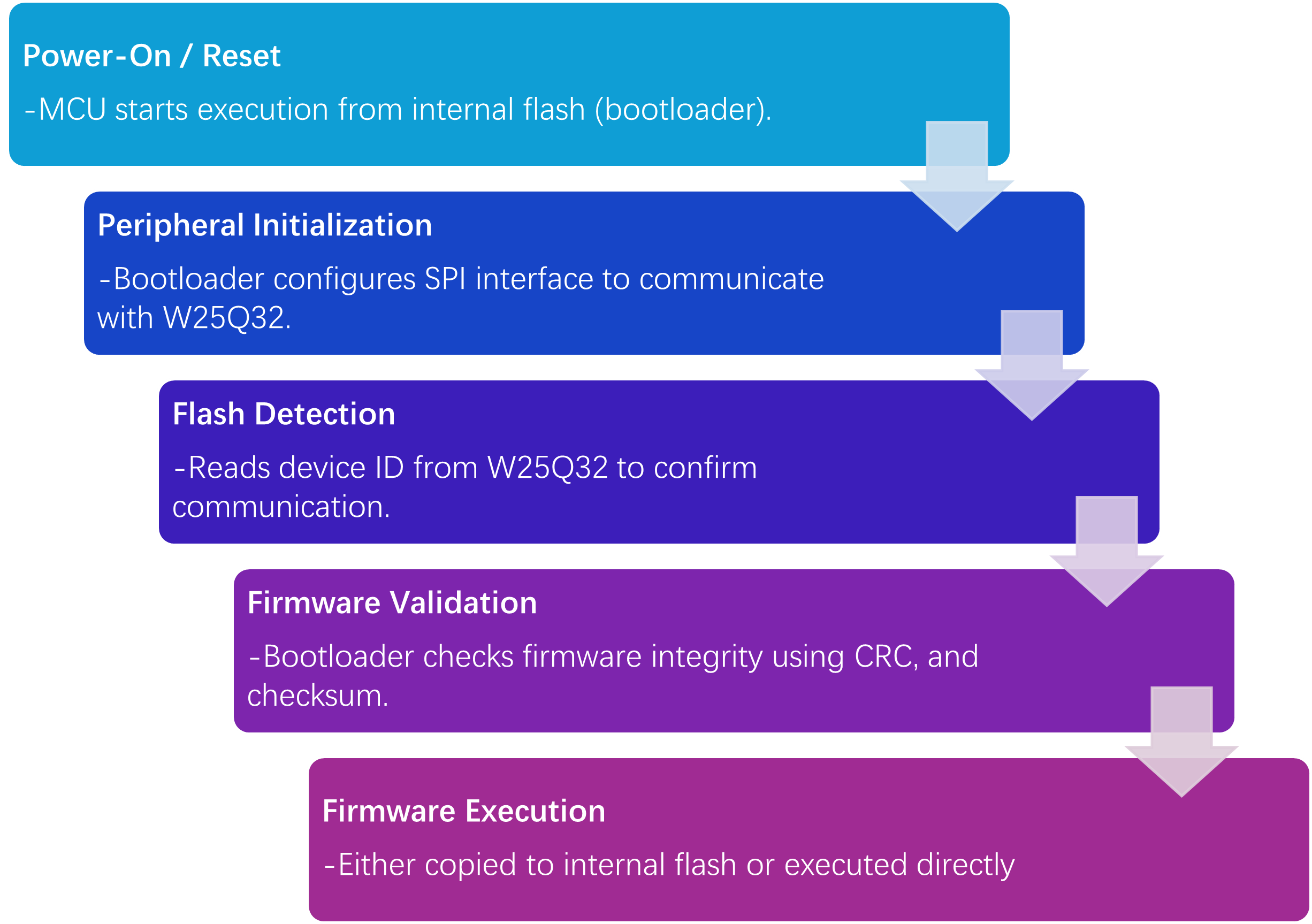
Boot Process Using W25Q32 SPI Flash
A typical SPI NOR flash boot process using W25Q32 follows the following sequence.
W25Q32 Flash Memory Interface Circuit with Microcontroller
Interfacing the W25Q32 SPI Flash with a microcontroller like STM32, ESP32, or nRF52840 is straightforward due to its standard SPI communication protocol. However, a reliable hardware design requires careful attention to signal connections, power stability, and pin configuration. In this section, I have explained the hardware interface guide of W25Q32 with the microcontroller. The same procedure may be applied to any microcontroller.
Typical Interface Overview
The W25Q32 Flash Memory connects to a microcontroller using the SPI bus, which consists of four primary signals, i.e., MISO, MOSI, SCLK, and CS.
| Signal | Full Form | Description |
|---|---|---|
| MOSI | Master Out Slave In | Data sent from MCU to flash memory |
| MISO | Master In Slave Out | Data sent from flash memory to MCU |
| SCLK | Serial Clock | Clock signal generated by MCU for synchronization |
| CS | Chip Select | Enables or selects the flash device for communication |
Typical Hardware Connection
| W25Q32 Pin | Connection | Description |
|---|---|---|
| VCC | 3.3V Supply | Power supply |
| GND | Ground | Common ground |
| CS | MCU GPIO (Chip Select) | Enables communication |
| CLK (SCLK) | MCU SPI Clock | Synchronizes data transfer |
| DI (MOSI) | MCU MOSI | Data input to flash |
| DO (MISO) | MCU MISO | Data output from flash |
| WP | Pull-up to VCC (via resistor) | Disable write protection |
| HOLD | Pull-up to VCC (via resistor) | Disable hold function |
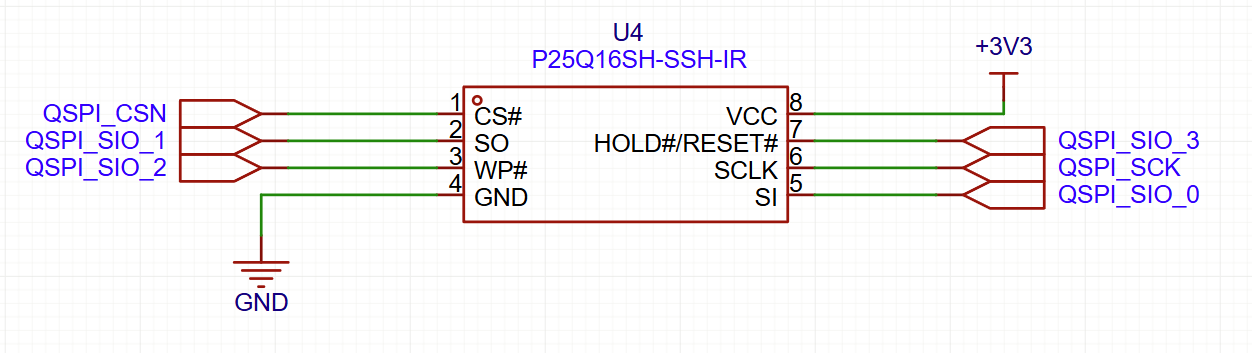
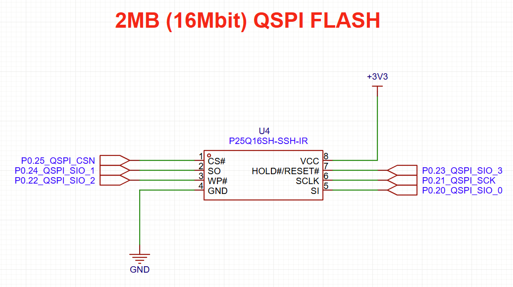
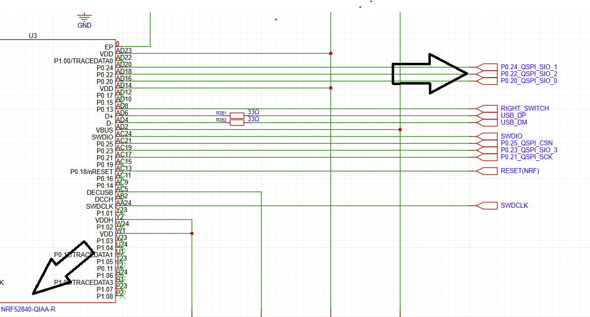
Different SPI Flash ICs Circuit with Microcontroller
There are various SPI flash ICs available, and which one is suitable for your embedded application is dependent on the application requirements. However, in this section, different SPI Flash ICs such as W25Q32, and P25Q16SH hardware circuti diagram are shown below for the embedded system designers.

For more information on how to use the W25Q32 SPI flash with a microcontroller like STM32, visit the link below.
Power Supply and Decoupling
Decoupling capacitor is very important in embedded system design as it prevents the device from voltage spikes, and ensure smooth and clean supply to the IC.
Therefore, always use a 0.1 µF decoupling capacitor placed close to the VCC pin and add a bulk capacitor of 10µF for noise filtering to ensure a clean 3.3V supply without voltage dips during write/read operation.
Firmware Update Strategies Using W25Q32
The W25Q32 Flash memory plays a critical role in enabling safe and flexible update mechanisms by acting as reliable SPI flash firmware storage for new and existing firmware images.
There are different firmware update strategies and methods that can be used for your embedded application. These methods are explained in this section. Using external flash memory for microcontroller applications like W25Q32 allows engineers to implement advanced update techniques that minimize these risks.
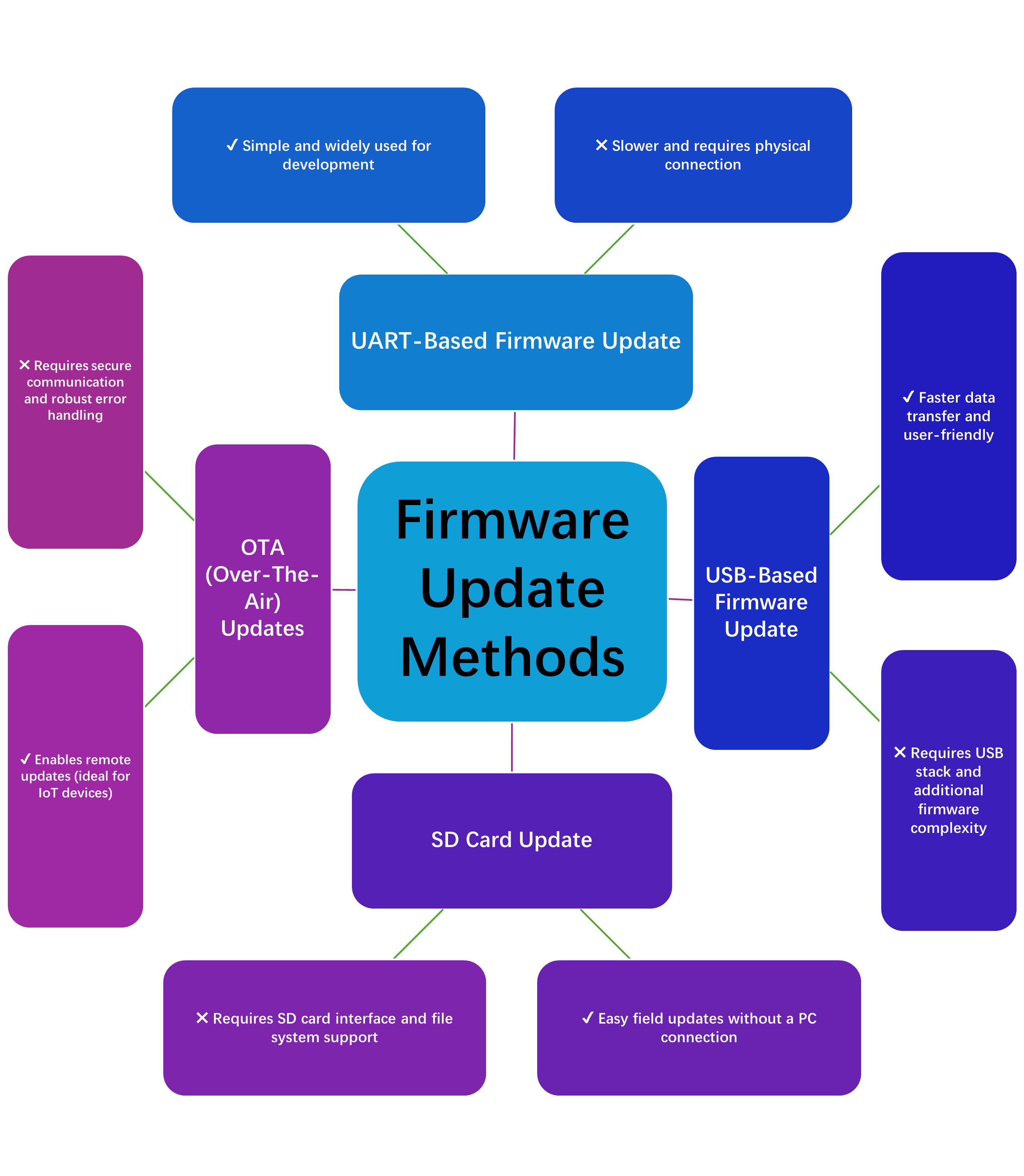
Common Firmware Update Methods
UART-Based Firmware Update
In a UART-based firmware update, the firmware is transferred via serial communication from a host system to the microcontroller, which then writes it into the W25Q32 Flash Memory. This method is simple, cost-effective, and widely used during development and debugging. However, it requires a physical connection and offers slower data transfer compared to other methods.
USB-Based Firmware Update
A USB-based firmware update allows firmware to be transferred through a USB interface, providing faster speeds and a more user-friendly experience. It is commonly used in consumer and industrial devices. While efficient, it requires implementing a USB stack, which increases firmware complexity.
SD Card Update
In an SD card update method, firmware is stored on an SD card, and the bootloader reads and programs it into the W25Q32 SPI Flash during system startup. This approach is useful for field updates where direct connectivity is not available. However, it requires additional hardware and file system support.
OTA (Over-The-Air) Updates
OTA updates enable firmware to be downloaded remotely via wireless communication such as Wi-Fi, Bluetooth, or cellular networks. The firmware is first stored in SPI flash firmware storage, like W25Q32, before being installed. This method is ideal for IoT devices but requires secure data transfer, validation, and robust error handling to ensure reliability.
Common W25Q32 Failures in Embedded Systems
W25Q32 SPI Flash Memory is reliable and widely used in embedded applications. However, there are some of the most common failures that engineers often encounter during the application design. These issues can be due to hardware design issues, firmware mishandling, or an improper firmware update process. This section will cover these common failures and how to avoid them to reduce design time.
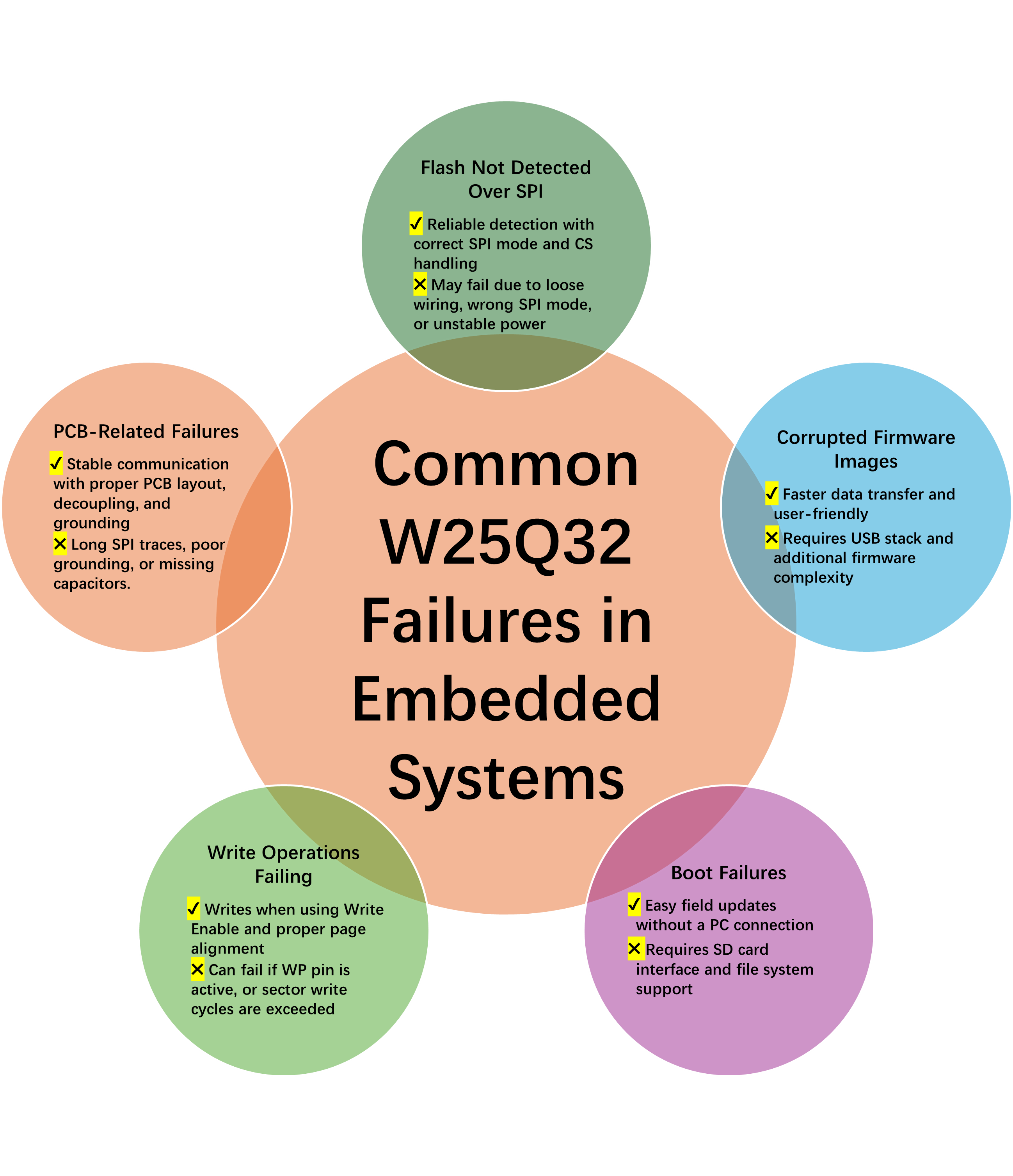
Flash Not Detected Over SPI
One of the most frequent issues is the microcontroller failing to recognize the W25Q32 flash. The most common causes are Incorrect SPI mode (e.g., Mode 0 vs Mode 3 mismatch), improper CS (Chip Select) handling, incorrect wiring, and power supply instability.
Write Operations Failing
Another common failure issue is when write or erase commands may fail if the flash is not properly configured. This is most common when Write Enable (WREN) command not issued before programming, Write attempts across non-aligned page or sector boundaries.
Corrupted Firmware Images
Another commonly occurring failure is when corruption can occur during firmware updates or storage. This can happen when power loss during write or erase operations, incomplete sector erases, and attempting to overwrite active firmware directly without a backup
Boot Failures
SPI flash also occur when bootloader may fail to load firmware from W25Q32 due to Invalid firmware image or corrupted header, SPI timing or signal integrity issues, and Incorrect memory mapping in bootloader.
Signal Integrity or PCB-Related Failures
Another most common issue of SPI flash failure is due to poor PCB layout. Mostly due to Long SPI traces causing reflections or noise, Lack of decoupling capacitors near VCC, and grounding leading to communication errors.
W25Q32 Alternatives
As we have discussed and learnt in this article, the external SPI flash memory plays a critical role in embedded systems as it provides firmware storage, bootloader execution, and firmware updates. While the W25Q32 Flash Memory is widely used, several alternatives can provide higher capacity, faster performance, or industrial-grade reliability, including Winbond W25Q64 / W25Q128, Micron N25Q32 / N25Q64, Macronix MX25L32 / MX25L64, SST25VF032 / SST25VF064, and even MCU-integrated NOR flash.
In this section, we will discuss other SPI flash and their performance, so that the embedded designers can easily identify which SPI flash suits their design according to their application requirements.
| SPI Flash | Capacity | Interface | Endurance | Speed | Features | Use Case |
|---|---|---|---|---|---|---|
| Winbond W25Q64 / W25Q128 | 8 MB / 16 MB | SPI / Dual / Quad | 100,000 P/E cycles | Up to 104 MHz | Quad SPI, compatible with W25Q32 command set | Dual-image firmware, large OTA updates |
| Micron N25Q32 / N25Q64 | 4 MB / 8 MB | SPI / Dual / Quad | 100,000 P/E cycles, industrial | Up to 108 MHz | Wide temp (-40°C to +85°C), reliable for harsh environments | Industrial IoT, rugged embedded systems |
| Macronix MX25L32 / MX25L64 | 4 MB / 8 MB | SPI / Dual / Quad | 100,000 P/E cycles | Up to 104 MHz | Standard SPI commands, widely available | Consumer electronics, moderate-speed applications |
| SST25VF032 / SST25VF064 | 4 MB / 8 MB | SPI / Dual / Quad | 100,000 P/E cycles | Up to 108 MHz | Fast write/erase cycles, reliable firmware storage | High-speed embedded firmware updates |
| MCU-Integrated NOR Flash | 32–128 MB | Internal NOR | 100,000 P/E cycles (varies) | MCU-dependent | No external chip needed, reduces PCB footprint | Compact embedded systems with limited external space |
Conclusion
To sum up, W25Q32 Flash memory is a versatile and reliable solution for embedded systems, offering robust SPI flash firmware storage for bootloaders, firmware updates, and fail-safe mechanisms. By understanding its key specifications, proper SPI signal connections, and best practices for hardware design, engineers can ensure stable operation and prevent common failures such as corrupted firmware, write errors, or bootloader issues. Furthermore, modern embedded applications, considering firmware update strategies like UART, USB, SD card, or OTA is crucial for maintaining device reliability and minimizing downtime.
FAQ (Frequently Asked Questions)
To interface the W25Q32 SPI Flash, connect MOSI, MISO, SCLK, and CS to the MCU’s SPI pins, provide a stable 3.3V power supply, and use pull-up resistors on WP and HOLD pins. Adding a 0.1µF decoupling capacitor near the IC is critical for stable operation.
If your W25Q32 Flash Memory is not detected, the issue is usually related to Incorrect SPI mode, improper Chip Select (CS) handling, Wiring or PCB connection issues, and a missing power supply.
To prevent corruption in SPI flash firmware storage, always use CRC or checksum validation before executing firmware, and avoid power loss during write/erase operations
Bootloader failures can occur due to corrupted firmware, incorrect memory mapping, SPI timing issues, or missing validation checks.
Popular alternatives include W25Q64/W25Q128 (higher capacity), Micron N25Q series (industrial reliability), Macronix MX25L series (cost-effective), and SST25VF series (fast write cycles).