At first glance, the varistor vs resistor comparison can be confusing. Both are two-terminal passive components used in electronic circuits, and both influence how voltage and current behave in a design.
Because the word varistor contains resistor, many people assume the two parts perform similar functions.
In reality, the difference between a varistor vs resistor is fundamental: resistors control current during normal circuit operation, while varistors mainly protect circuits from voltage surges.
Designers use resistors to limit current, divide voltage, create bias conditions, define logic levels, and measure current through a known voltage drop.
A varistor, on the other hand, is mainly a protection device. Under normal operating voltage, it remains highly resistive and has very little effect on the circuit.
When a voltage spike, transient, or surge appears, the varistor reacts by changing its resistance sharply and helping clamp the excess voltage before it can damage sensitive components.
That is why varistor vs resistor is not just a component comparison. It is really a comparison between normal circuit control and surge protection.
This difference matters more than it may seem. It affects how each part behaves electrically, where it should be placed in a schematic, how it should be selected, which specifications matter most, and what kind of failures can happen if the wrong component is used.
By the end of this guide, you will clearly understand the difference between varistor and resistor, including their function, behavior, symbol, applications, and selection criteria.
TL:DR
| Aspect | Resistor | Varistor |
| Main job | Control current, divide voltage, set bias levels, sense current | Clamp voltage surges and absorb transient energy |
| Resistance behavior | Fixed or intentionally adjusted to a known value | Changes sharply with applied voltage |
| Linear vs non-linear | Roughly linear over the normal operating range (Ohm’s Law behavior) | Strongly non-linear voltage-dependent behavior |
| Role in the circuit | Active during normal operation | Mostly inactive until a surge or transient appears |
| Typical position | In series paths, voltage divider networks, pull-ups, current shunts, feedback loops | Across supply rails, AC mains inputs, or sensitive signal lines |
| Key specs | Resistance value, tolerance, power rating (wattage), temperature coefficient (TCR), stability, pulse capability | Maximum continuous operating voltage (MCOV), varistor voltage, clamping voltage, surge current rating, energy rating, capacitance |
| Common applications | LED current limiting, voltage dividers, pull-up/pull-down networks, current sensing, timing and bias circuits | AC mains surge protection, power-entry protection, relay and solenoid transient suppression, appliance and industrial surge protection |
| Failure concerns | Overheating, resistance drift, overload damage, pulse stress | Increased leakage after repeated surges, degradation over time, possible thermal runaway if overstressed |
| Can it replace the other? | No | No |
What Is a Resistor?
A resistor is an electronic component designed to provide a specific resistance value in a circuit. That controlled resistance allows engineers to regulate current flow, create voltage drops, and stabilize circuit behavior.

In practical electronics, resistors are used for tasks such as current limiting, voltage division, biasing, defining logic levels, and measuring current through a shunt resistor.
Because their resistance value is predictable, resistors help ensure circuits behave consistently during normal operation.
How a Resistor Behaves
A key property of a resistor is its approximately linear relationship between voltage and current, commonly described by Ohm’s Law.
Within its operating range, a resistor maintains a stable ratio between voltage and current, allowing designers to predict circuit performance.
However, real resistors are not perfectly ideal. Their behavior is influenced by factors such as:
- Tolerance (how close the actual value is to the rated value)
- Temperature coefficient (TCR), which describes resistance changes with temperature
- Power rating, which determines how much heat the resistor can safely dissipate
- Long-term stability and pulse handling
Resistors normally convert electrical energy into heat during operation, which is why selecting the correct wattage rating is essential for reliable circuit design.
Common Resistor Types
Several resistor types are widely used in electronics:
- Chip resistors: Small surface-mount resistors used in most modern PCBs.
- Through-hole resistors: Traditional leaded components used in prototyping, repairs, and some power circuits.
- Shunt resistors: Very low-value resistors used for current sensing in power electronics and battery systems.
- Power resistors: Designed to dissipate higher levels of heat in power applications.
- Trimmer potentiometers: Manually adjustable resistors used for calibration and tuning.
These components help control normal circuit behavior, which contrasts sharply with the role of a varistor, whose main purpose is circuit protection.
What Is a Varistor?
A varistor is a voltage-dependent resistor whose resistance changes dramatically as the applied voltage increases.
Unlike a standard resistor, which maintains a relatively constant resistance, a varistor is intentionally non-linear.

In normal operating conditions, a varistor behaves like a very high-resistance device, allowing only a small leakage current to flow.
When the voltage rises above a threshold level, the device rapidly becomes more conductive. This allows it to clamp the voltage and absorb surge energy, protecting sensitive components in the circuit.
Because of this behavior, we use varistor for surge protection, transient suppression, and overvoltage protection in power electronics and electronic equipment.
How a Varistor Behaves
The defining characteristic of a varistor is its non-linear current–voltage relationship.
- At normal voltages, the device has high impedance and remains mostly inactive.
- When a voltage spike or transient occurs, the impedance drops sharply.
- The varistor then conducts current and limits the peak voltage seen by the rest of the circuit.
It is important to note that a varistor does not clamp voltage to a perfectly fixed value.
As the surge current increases, the clamping voltage also rises, which is why engineers evaluate both the varistor voltage and the clamping voltage at a specified surge current when selecting a device.
In simple terms, a resistor helps control everyday circuit behavior, while a varistor acts as a protective device that responds only when abnormal voltage conditions occur.
Common Varistor Types
Although we use the term varistor interchangeably with MOV (Metal Oxide Varistor), several varistor technologies exist. Each type has different voltage ranges, surge environments, and circuit sizes.
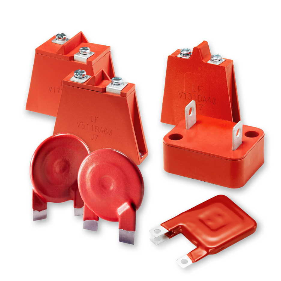
Metal Oxide Varistor (MOV)
The Metal Oxide Varistor (MOV) is one of most important varistor type in power electronics. It consists of zinc oxide grains pressed into a ceramic-like structure that creates many diode-like junctions inside the device.

Engineers use it for surge suppression in AC mains circuits, power supplies, industrial equipment, and consumer electronics.
They can absorb large surge currents and energy from events such as lightning strikes or switching transients.
Because of their energy-handling capability, MOVs are the default choice for most overvoltage protection designs.
Multilayer Varistor (MLV)
A Multilayer Varistor (MLV) is a compact surface-mount varistor. Engineers use it to protect sensitive electronic circuits from ESD (electrostatic discharge) and fast transients.

MLVs are constructed using multiple ceramic layers similar to multilayer ceramic capacitors (MLCCs), which allows them to be manufactured in very small SMD packages.
Compared with MOVs, MLVs handle lower surge energy but offer faster response and smaller package sizes.
Automotive and High-Energy Varistors
Some varistors are specifically available for high-energy surge environments, such as automotive electrical systems or industrial equipment.
These devices typically offer:
- higher surge current ratings
- improved thermal stability
- extended operating temperature ranges
- increased reliability for harsh environments
Thermally Protected MOV Assemblies
In high-reliability applications, MOVs can combine with thermal protection mechanisms, such as thermal fuses or integrated disconnect structures.
These assemblies help prevent thermal runaway or fire risk if the MOV degrades after repeated surge events.

Varistor vs Resistor: Side-by-Side Technical Comparison
Understanding varistor vs resistor becomes clearer when you compare their electrical behavior and design purpose directly.
Although both components involve resistance, their characteristics and roles in circuits are fundamentally different.

1. Resistance Behavior
A resistor is chosen because its resistance is known and controlled. Even though real components may drift slightly due to temperature or aging, the goal is still a stable value within a specified tolerance.
For example, a 10 kΩ resistor should behave like a 10 kΩ device within its tolerance range rather than changing dramatically with applied voltage.
A varistor, on the other hand, is useful precisely because its resistance is not constant. Its impedance changes sharply when the applied voltage approaches the surge region.
Under normal voltage conditions, the device maintains very high impedance and allows only a small leakage current.
When a transient voltage spike occurs, the impedance collapses rapidly, allowing current to flow and enabling the varistor to clamp the overvoltage.
2. I-V Characteristic
In a varistor vs resistor analysis, resistance behavior and I-V characteristics reveal the most fundamental differences.
The electrical behavior of a resistor is largely linear. The current–voltage relationship follows Ohm’s law, meaning the ratio of voltage to current remains roughly constant over the normal operating range.
This predictable linear behavior makes resistors ideal for calculations and circuit design.
A varistor, in contrast, is strongly non-linear. Its current–voltage curve shows very little current flow at normal voltage levels, followed by a sharp increase in conduction once the threshold region is reached.
This sudden change in behavior allows the device to absorb transient energy and limit voltage spikes.
Another useful feature is that most metal oxide varistors (MOVs) are bidirectional, meaning they respond to both positive and negative voltage surges.
This makes them well suited for AC surge protection, where voltage polarity alternates.
3. Main Purpose
The primary purpose of varistor vs resistor varies.
The primary purpose of a resistor is circuit control. Designers rely on resistors to:
- limit current
- divide voltage
- set bias conditions
- establish pull-up or pull-down states
- sense current
- stabilize timing networks
Even when resistors dissipate heat, they are still performing their intended function as part of the circuit’s normal operation.
The primary purpose of a varistor is protection. Devices such as MOVs are to suppress transient overvoltage events in electronic systems.
Instead of shaping everyday circuit behavior, they absorb or redirect surge energy when abnormal voltage conditions occur.
4. Placement in Circuits
Varistor vs Resistor behave differently in circuits due to its placements.
Because resistors define circuit behavior, they appear in many positions within a design. Typical placements include:
- series current-limiting paths
- voltage divider networks
- pull-up or pull-down connections in digital logic
- feedback networks in amplifiers
- current-sensing paths in power electronics
The position of the resistor depends on the function it performs.
Varistors are placed differently. They connect across nodes that require protection, rather than within the signal path itself. Common locations include:
- across AC mains inputs (line to neutral)
- across power supply rails
- across nodes exposed to inductive switching transients
- across inputs to sensitive electronic circuits
In these positions, the varistor remains inactive during normal operation but quickly conducts when a surge appears.
5. Power and Stress Profile
Resistors are primarily for continuous power dissipation. During normal operation they convert electrical energy into heat, and their wattage rating determines how much heat they can safely handle.
In some applications, designers must also consider pulse handling capability, especially in circuits with switching events or transient loads.
Varistors operate under a very different stress profile. They can handle short transient events, not sustained overvoltage conditions.
Surge ratings are typically defined using standardized waveforms, such as the 8/20 microsecond surge waveform commonly used in surge testing.
If the surge energy exceeds the device’s rating or persists for too long, the varistor can overheat and potentially enter thermal runaway.
For this reason, varistors are typically used in conjunction with proper system protection strategies and sometimes additional protective components.
6. Key Specifications Engineers Look At
When selecting a varistor vs resistor, engineers typically evaluate several key parameters beyond the basic resistance value:
- Resistance value
- Tolerance
- Rated power dissipation
- Temperature coefficient of resistance (TCR)
- Long-term stability
- Package type
- Pulse load capability
These parameters ensure the resistor behaves predictably under real operating conditions.
When selecting a varistor, different specifications become important because the component is intended for surge protection rather than continuous control.
Engineers typically evaluate:
- Maximum continuous operating voltage (MCOV)
- Nominal AC or DC rating
- Varistor voltage (threshold region)
- Clamping voltage at a specified surge current
- Peak pulse current rating
- Energy absorption rating
- Capacitance (important for signal lines)
- Package style and environmental limits
These parameters determine how effectively the varistor can protect the circuit during transient events.
Varistor vs Variable Resistor
Because the word varistor contains resistor, many readers assume it is simply another type of variable resistor.
In reality, these components behave very differently and are used for completely different purposes in electronic circuits.
A variable resistor is a resistor whose resistance can be manually adjusted by the user or technician. The most common examples are potentiometers, trimmers, and rheostats.
These devices include a mechanical adjustment—such as a rotating shaft or tuning screw—that changes the resistance value in a controlled way.
Engineers use variable resistors when they need to fine-tune circuit behavior, such as adjusting signal levels, calibrating sensors, setting reference voltages, or controlling audio volume.
In these cases, the resistance value is deliberately changed by the designer or user to achieve a specific electrical result.
A varistor, by contrast, is not manually adjustable. Its resistance changes automatically in response to voltage.
At normal operating voltage, the device behaves like a very high resistance component and allows only a tiny leakage current to flow.
When the voltage rises above its threshold—such as during a surge or transient—the varistor rapidly becomes conductive and helps clamp the excess voltage.
This automatic voltage-dependent behavior is why a varistor is classified as a non-linear protection component, rather than a tuning or control element.
Key Differences
| Feature | Varistor | Variable Resistor |
| Resistance control | Changes automatically with voltage | Adjusted manually by the user |
| Electrical behavior | Strongly non-linear | Mostly linear |
| Main purpose | Surge and overvoltage protection | Circuit tuning and adjustment |
| Typical devices | Metal Oxide Varistor (MOV), multilayer varistor | Potentiometer, trimmer, rheostat |
| Circuit role | Protective component | Functional circuit control |
In short, a variable resistor helps tune how a circuit operates, while a varistor protects the circuit from voltage spikes. Despite the similarity in their names, they serve very different roles in electronics design.
Varistor vs Resistor Applications in Real Circuits
Looking at real circuit examples is one of the easiest ways to understand the difference between a varistor vs resistor.
Both components appear in practical electronic designs, but they serve very different roles.
A resistor shapes how a circuit behaves during normal operation, while a varistor protects the circuit when abnormal voltage events occur.
Common Resistor Applications
Because resistors provide stable and predictable resistance, they appear in almost every type of electronic system—from simple LED circuits to complex industrial controllers.
Voltage Dividers
One of the most common resistor uses is the voltage divider network. By placing two resistors in series, engineers can create a fixed voltage ratio.
This technique is widely used to:
- scale down high voltages for microcontroller ADC inputs
- create reference voltages in power supply feedback loops
- interface sensors that output voltages outside a processor’s range
Voltage dividers are common in power regulation circuits, battery monitoring systems, and embedded control boards.
Pull-Up and Pull-Down Networks
Resistors are also used to define stable logic states in digital electronics.
In interfaces such as I²C, SPI, or open-drain communication buses, a pull-up resistor returns a signal line to logic high when no device is actively driving the line. Similarly, pull-down resistors ensure a signal returns to logic low.
The resistor value directly influences:
- signal rise time
- power consumption
- communication reliability
For example, in an I²C bus, the pull-up resistor must balance speed and current consumption to ensure reliable communication.
Current Limiting
Another classic resistor application is current limiting, especially in LED circuits.
LEDs require precise current control. If the current becomes too high, the LED can overheat and fail. A resistor placed in series with the LED limits the current to a safe level.
This technique is widely used in:
- indicator LEDs
- display backlighting
- simple lighting circuits
- microcontroller development boards
Current Sensing with Shunt Resistors
Low-value shunt resistors allow engineers to measure current by observing the small voltage drop across the resistor.
These components are essential in:
- battery management systems (BMS)
- power supplies and DC/DC converters
- motor control systems
- electric vehicle electronics
- industrial power monitoring
Because the resistance is extremely low, the resistor must be precisely manufactured and thermally stable to maintain measurement accuracy.
Biasing and Analog Signal Control
Resistors also form bias networks in analog circuits. These networks establish operating points for devices such as:
- transistors
- operational amplifiers
- analog sensors
For example, in amplifier circuits, resistor ratios determine gain and stability. In transistor circuits, they establish the correct base or gate bias to keep the device operating in its intended region.
Timing and RC Networks
When combined with capacitors, resistors create RC time constants that control timing behavior.
These networks are used in:
- oscillator circuits
- filters
- delay circuits
- analog signal conditioning
The resistor determines how quickly the capacitor charges or discharges, which directly sets the timing characteristics of the circuit.
Common Varistor Applications
Unlike resistors, varistors are rarely used to control normal circuit behavior. Instead, they serve as protective components that suppress voltage surges and transients.
Most real-world applications use metal oxide varistors (MOVs) because they can absorb significant surge energy while remaining relatively inexpensive.
AC Mains Surge Protection
One of the most common uses of varistors is AC mains surge protection.
Power grids can experience voltage spikes caused by:
- lightning strikes
- switching of large inductive loads
- faults in distribution systems
- nearby industrial equipment
MOVs are often placed across line and neutral or line and earth to absorb these surges before they reach sensitive electronics.
This type of protection is common in:
- surge protectors
- power strips
- household appliances
- industrial equipment
Power Supply Input Protection
Varistors are frequently placed at the input stage of switching power supplies.
In this position, they help protect internal components such as:
- bridge rectifiers
- switching MOSFETs
- PWM controllers
- filter capacitors
Without surge suppression, voltage spikes could damage these components and lead to system failure.
Inductive Load Transient Suppression
Inductive loads such as motors, relays, and solenoids generate voltage spikes when the current through them is suddenly interrupted.
Varistors can be placed across these loads to absorb the resulting transient energy.
Common examples include:
- relay coils in industrial control systems
- motor drivers
- electromagnetic actuators
- solenoid valves
In these applications, the varistor prevents the transient voltage from damaging control electronics.
Appliance and Industrial Equipment Protection
Many consumer and industrial products include MOVs to improve reliability and safety.
Examples include:
- washing machines
- refrigerators
- HVAC controllers
- industrial motor drives
- programmable logic controllers (PLCs)
These systems often operate in electrically noisy environments where surge protection is essential.
Telecom and Interface Protection
Communication interfaces connected to long cables can also experience transient voltage events.
Varistors are sometimes used to protect:
- telecom equipment
- network interfaces
- industrial communication systems
In these cases, the varistor absorbs surge energy before it can propagate deeper into the electronics.
How to Choose the Right Varistor
A properly selected varistor remains high-impedance during normal operation, allowing only tiny leakage current.
When a surge occurs, it quickly becomes conductive and clamps the overvoltage, protecting sensitive components in the circuit.
The following sections explain how each of these specifications affects real-world varistor selection.
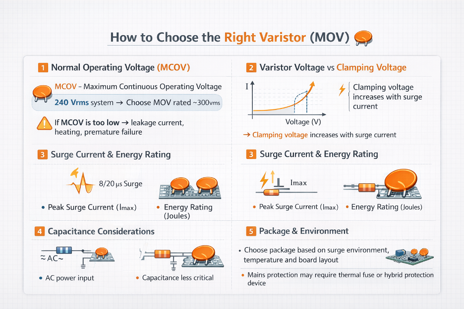
Start with normal operating voltage
The first rule is simple: the varistor must survive the normal system voltage without conducting significant current. Bourns describes this through MCOV, the maximum continuous operating voltage.
For AC mains protection, the MOV’s continuous RMS rating must sit above the system’s normal RMS voltage. Bourns gives the example of using a 300 Vrms MOV on 240 Vrms equipment.
This is one of the most common selection mistakes. If the continuous rating is too low, the MOV can leak excessive current, self-heat, degrade over time, and fail even without a dramatic surge event.
Check varistor voltage and clamping voltage
These two numbers are related, but they are not the same. Varistor voltage is commonly specified at a low DC test current, often 1 mA, and helps indicate where the device enters its non-linear region.
Clamping voltage, however, is the more practical number during an actual surge because it tells you what voltage the protected circuit may really see at a given transient current.
Bourns also notes that clamping voltage rises as surge current rises. That means engineers should compare datasheet clamping values and curves at realistic surge levels rather than choosing only by nominal threshold voltage.
MOV selection guide explains that the maximum continuous operating voltage (MCOV) must exceed the system’s normal operating voltage.
Check surge current and energy rating
A varistor is a transient absorber, so it must be sized for the surge environment the product will actually face.
Littelfuse’s ZA datasheet lists peak pulse current and single-pulse energy ranges, while Bourns emphasizes that MOV surge performance is defined on short waveforms such as 8/20 µs.
That is the right mindset: short, high-energy events, not continuous overload.
If your application sees stronger surges, a larger MOV disc or more robust family can usually handle more current and energy, and often clamp at a lower voltage at higher current.
Consider capacitance if the line is sensitive
Capacitance is easy to ignore until it starts affecting circuit performance. Littelfuse includes typical capacitance values in its MOV tables, and those values can vary widely by part.
On power inputs this may not matter much. On data lines, telecom paths, or faster interfaces, added capacitance can affect loading, edge rate, and signal integrity.
So if the varistor is protecting a signal-sensitive node, do not stop at voltage and surge ratings alone. Two parts may look similar on headline specs but behave quite differently because of capacitance.
Match package and environment
Package style affects more than board fit. Littelfuse’s ZA family is available in multiple leaded sizes, and those different sizes bring different surge and energy capabilities.
Ambient temperature, creepage and clearance, mounting method, and expected surge environment all influence the right choice.
If the application is exposed to AC mains, safety architecture matters too.
In some designs, the right answer is not simply “pick a MOV,” but “pick the right MOV and combine it with thermal protection or a hybrid protector.”
Final Thoughts
The choice between a resistor vs varistor depends entirely on the role the component must play in your circuit.
Understanding the varistor vs resistor distinction helps engineers design circuits that are both functional and protected.
Use a resistor when you need predictable electrical behavior during normal operation. Use a varistor when the goal is overvoltage protection.
In many practical designs, the correct approach is not choosing one or the other. Instead, both components work together:
- Resistors manage normal circuit operation.
- Varistors protect the circuit during abnormal electrical events.
This combination is common in power supplies, industrial control systems, consumer electronics, and AC mains interfaces, where predictable operation and surge protection are equally important.
If you are designing or sourcing protection components, Flywing Tech offers a wide range of electronic components, including varistors, resistors, and other circuit protection devices suitable for embedded systems, power electronics, and industrial applications.
Exploring reliable component options can help ensure your design remains both stable during normal operation and resilient during voltage surges.
If your design requires reliable surge protection, you can explore a range of metal oxide varistors (MOVs) suitable for power electronics and industrial systems here.
FAQ
Is a varistor a type of resistor?
Yes, in the broad sense that it is a two-terminal resistive component, but it is not a standard linear resistor. A varistor is a voltage-dependent, non-linear resistor used mainly for surge protection.
What is the main difference between a varistor and a resistor?
A resistor is used for predictable, continuous circuit control. A varistor is used for transient overvoltage protection and changes impedance sharply when voltage rises into its protection region.
Can I use a varistor instead of a resistor?
Not for normal design roles such as pull-ups, dividers, LED current limiting, or current sensing. A varistor’s impedance is intentionally non-linear, so it cannot replace a stable resistor in those jobs.
Does a varistor limit current like a resistor?
Not in the same way. A resistor limits current through a predictable resistance value. A varistor mainly clamps overvoltage by becoming more conductive when the voltage exceeds its threshold region.
Where should a varistor be placed in a circuit?
Typically across the line, supply input, or other node being protected from transient energy, rather than in the normal signal path. AC mains, power supply circuits, motor control, telecom, and solenoid-related protection are common examples.
What happens when a varistor fails?
If overstressed, leakage current can increase, self-heating can rise, and the device can move toward thermal runaway. In severe cases it can fail destructively, which is why thermal protection or coordinated protection design is important.
Is a MOV the same as a varistor?
A MOV is the most common practical type of varistor used in electronics and power-entry protection, but “varistor” is the broader category term. In most everyday discussions, though, MOV is what people mean.
