Introduction
Transistors are the fundamental building blocks of modern embedded systems because millions of transistors together form the integrated circuits that make modern memory devices, microprocessors, and microcontrollers. They are also extensively use in electronic circuits for switching, amplification, and signal processing. The transistors come with various distinct features that determine the application where they can best fit.
For instance, MOSFET transistors are primarily use in high frequency switching and low power consumption. Whereas, BJT transistors are primarily use in low frequency and analog applications such as audio amplification, and low frequency switching. One such NPN transistor is BC547.
BC547 is a general-purpose Bipolar Junction Transistor (BJT) that is widely used in low current and low noise applications, such as sensor interfacing, amplification, and switching. There are other BJT transistors also available, such as C945 and 2N2222, but each transistor has its own distinct features. By understanding the distinct features of these transistors, one can decide which specific transistor is suitable for their application. In this article, I will cover a comprehensive guide of the BC547 NPN transistor that includes its pinout, characteristics, circuit design, and practical applications with software simulations.
What is BC547 Transistor?
A transistor is an electronic device that controls the flow of electric current. BC547 is a type of NPN transistor that has three terminals, i.e., base, emitter, and collector. These NPN transistors are use in switching and amplification applications. A transistor like BC547 can either be use as a switching device or an amplification device. The mode of operation is determine by the transistor operating region. There are three regions of operation of a transistor, i.e., the cut-off region, saturation region, and active region. To use the BC547 transistor as a switching device, operate the transistor in the cutoff and saturation regions. However, to use it as an amplification device, operate the transistor BC547 in the active region.

The BC547 transistor is known for its small signal current gain of a maximum of 900 and fast switching speed. Its high amplification and fast switching capabilities make it perfect for audio amplification circuits, sensor interfacing with microcontrollers, signal processing, LED drivers, motor speed control using PWM, and relay switching circuits.
To operate the BC547 as a switching device, it is use in the saturation and cutoff regions. In the cutoff region, collector-to-emitter voltage (VCE) is 50V, and the base-to-emitter voltage (VBE) should be 0V. In this condition, the BC547 acts as an OFF switch. On the other hand, in the saturation region, the base-to-emitter voltage should be greater than 0.7V with a base current of 0.5mA and BC547 acts as an ON switch.
It is recommended to use the datasheet for the exact values of the BC547 transistor and its different variants.
BC547 PIN Configuration
The BC547 transistor has three terminals: base, emitter, and collector. Proper understanding, working, and knowledge of the BC547 pinout helps the designer to efficiently integrate the BC547 in their circuit application. Many famous manufacturing companies like Fairchild, STM electronics manufacturer BC547, and it mostly come in TO-92 and SMD packages.

Pin Configuration of BC547 Transistor
| PIN Number | PIN Name | PIN Function |
|---|---|---|
| 1 | Collector | It is the output or load pin. This pin is connected to the load. |
| 2 | Base | This is the controlling pin of the transistor. |
| 3 | Emitter | This is the output pin from which the current leaves the transistor. |
The BC547 transistor has a simple pinout, high amplification gain, faster switching speed, and ease of use, making it suitable for a wide range of applications that include audio amplifiers, switching control circuits, LED drivers, and sensor interfacing with microcontrollers.
BC547 Circuit Design and Working Operation
By understanding the role and function of each pin of the BC547 transistor, we can easily understand the working operation of the BC547 transistor and its circuit design. In this section, with the help of a basic circuit, i.e., a transistor as a switching device, I will explain the working operation of BC547 so that one can design circuits with BC547 for their own specific applications.

The BC547 working operation depends on properly adjusting the voltage between base and emitter, known as VBE. To operate the transistor as a switching device, it must be properly turned ON and OFF. To turn it ON, the base must be forward biased, i.e., 0.7V with respect to the emitter. Similarly, to turn the BC547 off, the VBE must be zero, and no current should flow from the base terminal. This is important because the base terminal is the controlling terminal; a small change in base current will produce a large current at the collector terminal. The transistor does it using the current gain known as beta (β). BC547 has a maximum current gain of 800.
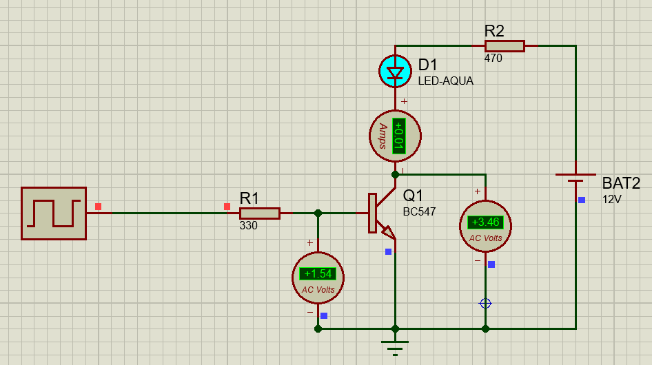
In the above example, BC547 is use to turn the LED ON and OFF. Base and collector resistors are used with values of 330 ohms and 470 ohms, respectively. The BC547 is operating in a common emitter configuration. In a common emitter configuration, the emitter terminal is connected to GND. The output is taken across the collector, and the input is applied at the base terminal.
When input is Low logic [Square Wave = 0]
A square wave with a 1Hz frequency is applied at the base terminal of BC547. At logic low, when the square wave is zero, no current will flow from the base terminal, and therefore, BC547 goes into the cutoff region and LED remains OFF. In other words, the base terminal does not allow the current to flow from collector to emitter, making the LED OFF. This is shown in the Figure above.
When input is High logic [Square Wave = 1]
At logic high, when the square wave is giving logic high, the base to emitter voltage is greater than 0.7 volts, which allows the current to flow from base to emitter terminal. In other words, current flowing from the base terminal enables the current to flow from collector to emitter, making the LED in an ON condition as shown in the figure above. To calculate the collector current when the LED is ON, apply the KVL, which results in;
\[
+12V – I_c R_c – V_{CE} = 0
\]
\[
+12V – I_c (470 \, \Omega) – 2.87 = 0
\]
VCE is 2.87 because the LED voltage is 2.2 volts and 0.7 volt is the voltage drop across transistor.
\[
9.13 – I_c (470) = 0
\]
\[
I_c = \frac{9.13}{470}
\]
\[
I_c = 0.01942 = 19.42 \,\text{mA}
\]
Electrical Characteristics of BC547
The electrical characteristics of the BC547 transistor play an important role in designing circuit applications and troubleshooting. Understanding its Characteristics help you understand the minimum and maximum limitations of transistors. Therefore, plays a crucial role in designing the circuit applications exactly as per the requirements with accuracy and efficiency.
Electrical Characteristics of BC547 Transistor
| Parameter | Value | Function |
|---|---|---|
| Collector Emitter Voltage (VCEO) | 45V maximum | When the base voltage is zero, the maximum VCEO is 45V. |
| Base Emitter Voltage (VBE) | Maximum 6V | This is the maximum allowable voltage between base and emitter junction. |
| Collector Current (IC) | 100mA | This is the maximum load current that BC547 can handle. |
| DC current gain or small signal gain | Typically, 200–300, and a maximum of 900 | This defines the BC547 transistor current gain. It defines the transistor amplification factor. |
| Junction Temperature | Up to 150°C | This is the transistor temperature operating range after that it will breakdown. |
| Gain Bandwidth Product | 300MHz | Maximum frequency at which the BC547 can provide useful gain. |
| Collector Emitter Saturation Voltage | Typically, 0.25V at IC of 10mA | This is the saturation voltage of BC547. |
| Base Emitter Saturation Voltage | 0.7V | This is the voltage needed to turn ON the BC547. |
Practical Circuit Applications with BC547 Transistor
Theory without practical implementation is of no use. In this section, I have use BC547 transistor and made the following practical application circuits in Proteus software. The circuit simulation and results of these application circuits show the remarkable potential of the this transistor in both analog and digital circuit design.
- Astable Multivibrator Circuit
- Dark Detector Circuit
- DC Motor Control using
- Hartley Oscillator circuit
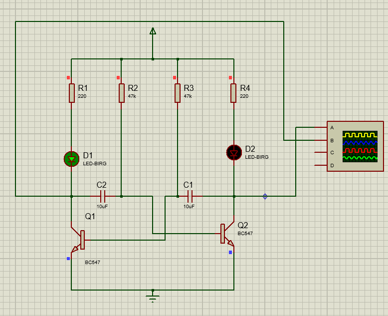
Astable Multivibrator Circuit using BC547
Astable multivibrators are types of relaxation oscillators. A stable multivibrator is a circuit use in electronic circuits to produce a constant square wave output. Unlike other multivibrators, which generally require an external trigger to produce the square wave output waveform. A stable multivibrator does not require an external trigger because it has an auto built-in trigger that switches it between two unstable states. Therefore, it is known as an astable multivibrator.
A simple astable multivibrator circuit is made using the two BC547 switching transistors that are grounded emitter cross-coupled transistors. Connect both transistors in a common emitter configuration. Two capacitors and a pair of resistors to form a cross-couple feedback network are use for oscillation between two states as shown in the circuit diagram.
Let’s suppose that when we apply the power (9V), the transistor Q1 turns ON before Q2 turns ON. When the Q1 is ON, it charges the capacitor that is connected to Q2’s base, and Q2 remains OFF. When the capacitor C2 charges enough it Turn ON the Q2 and Q1 will go OFF. This process repeats and a series of square waves across the collector terminal of both Q1 and Q2 produces as shown in circuit and output waveform of astable multivibrator. NE555 is a ready to use astable multivibrator IC. You can find it on flywing tech website.


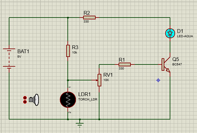
Dark Detector Circuit using BC547
A dark detector is an electronic circuit that senses the darkness and automatically turns ON the light. The basic components use in the dark detector circuit are a BC547 transistor and a Light Dependent Resistor (LDR). We connect the LDR in series with the resistor to form a voltage divider at the bae of the transistor as shown in the circuit diagram. The LDR senses the darkness, and the transistor switches the light ON or OFF. One such common LDR available is GL5528.
In the presence of light, the resistance of LDR is very low, and thus no voltage appears on the base terminal of BC547, and light remains OFF. However, when the darkness comes, the LDR resistance keeps increasing, and it increases the voltage across the base terminal of transistor. When the base voltage exceeds 0.7V, BC547 conducts and it turns ON the light. Therefore, it works as an automatic night light circuit. This circuit is usually use in street lights and in sports stadiums.

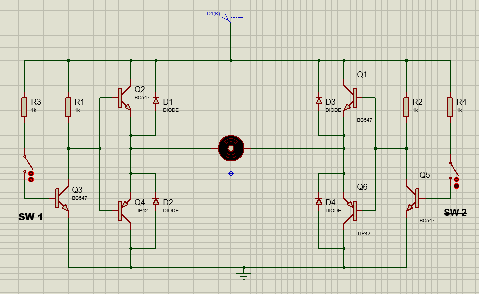
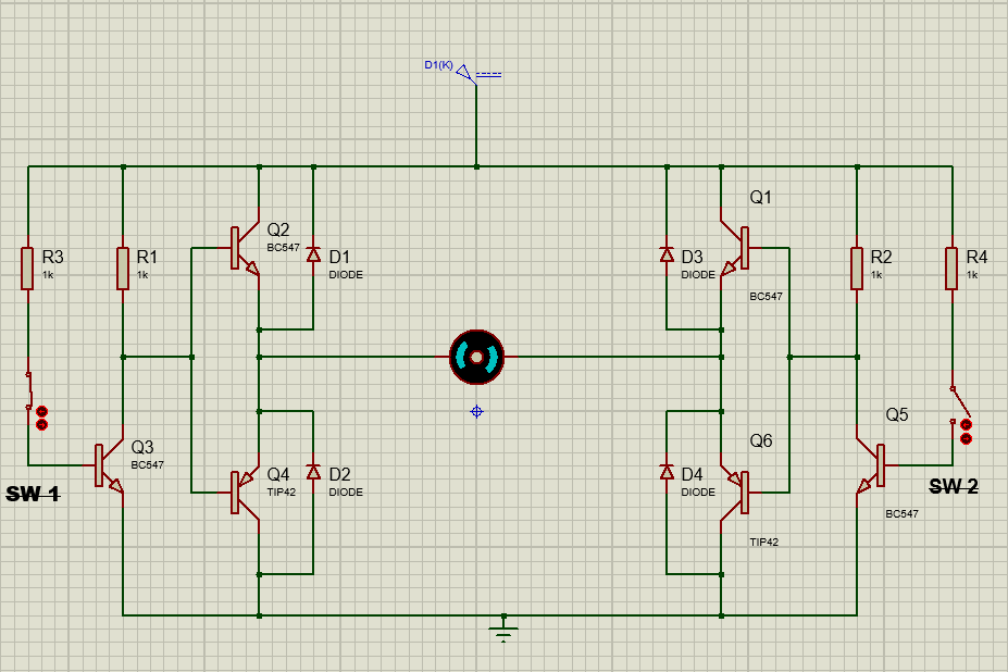
DC Motor Control using BC547
Another application of the is the DC motor direction control. A simple circuit using BJT transistor is use to control the direction of the DC motor in forward or reverse direction. A simple DC motor control circuit is made using the BC547 transistors, switch, and DC motor as shown in the circuit diagram.
When SW 2= 1 and SW 1= 0
To run the DC motor in the forward direction, close the SW 2. When switch 2 is close, transistor Q5 will turn ON and it will turn ON the Q6 transistor. Because the SW 1 is OFF, there is no sufficient base voltage for Q4 to turn ON. However, the Q2 transistor will turn ON. The transistors Q2 and Q6 in the ON condition, run the motor in the forward direction.
When SW 2= 0 and SW 1= 1
To run the DC motor in the reverse direction, close the SW 1. When switch 1 is close, transistor Q3 will turn ON and it will turn ON the Q64transistor. Because the SW 2 is OFF, there is no sufficient base voltage for Q6 to turn ON. However, the Q1 transistor will turn ON. The transistor Q1 and Q4 are in the ON condition run the motor in the reverse direction.
You can also find the custom built in motor drive IC (L298N) for your PCB design project on flywing tech website.

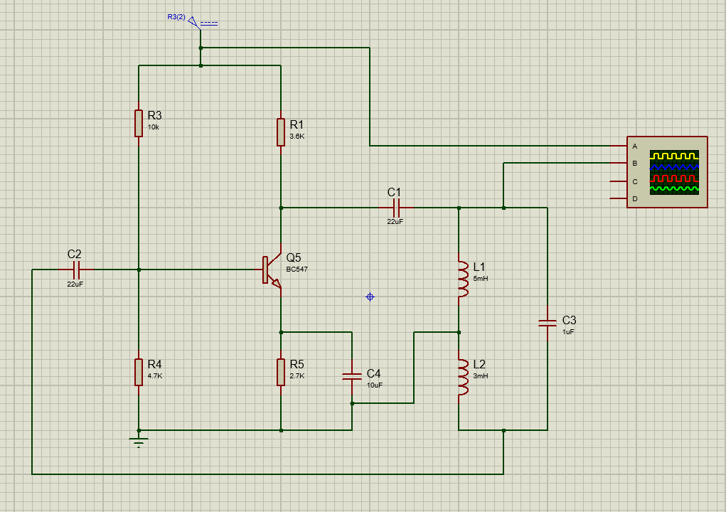
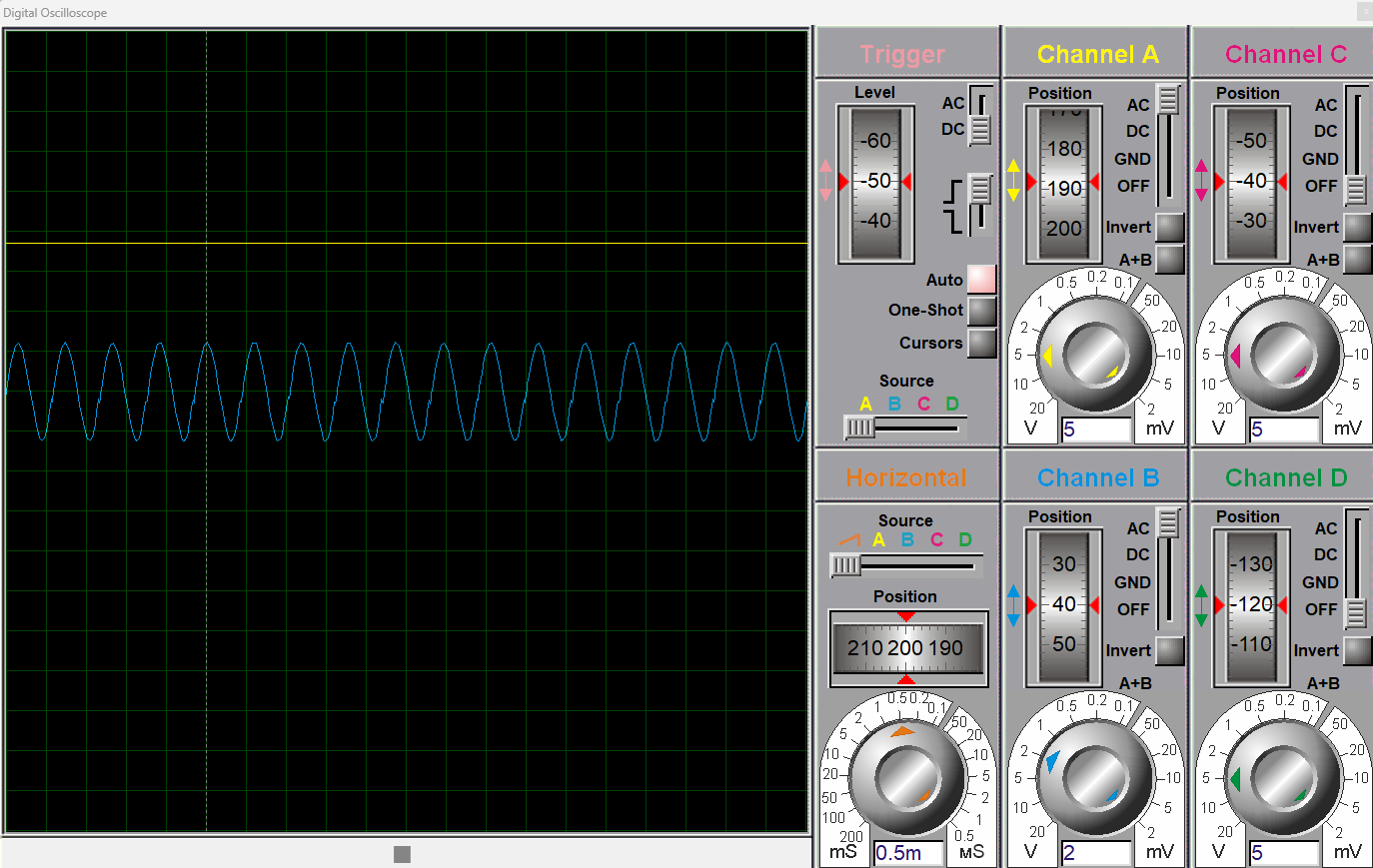
Hartley Oscillator circuit using BC547
The BC547 transistor is also use to construct the Hartley oscillator circuit. An oscillator is a circuit that produces constant oscillations at the output, such as a square wave, a triangular wave, and a sine wave. The Hartley oscillator is a type of oscillator that produces a sine wave output using the transistor and a tuned LC tank, as shown in the circuit diagram.
To form the Hartley oscillator circuit, BJT transistor is use in a voltage divider configuration along with an LC circuit and a feedback network for stable oscillations.
When the power is ON, the capacitor in the LC tank starts charging. As the capacitor charges, it will start discharging through the inductor. The conversion of electrical and magnetic energy between the inductor and the capacitor produces oscillation at the output. The frequency at which the Hartley oscillator produces the oscillation depends on the values of the inductor and the capacitor. The BC547 is configure in a common emitter configuration, and when a part of the signal is fed back to the transistor, it amplifies the signal and introduces a 180-degree phase shift. This process repeats and a stable sine wave is produce at the output. These circuits are widely use in radio circuits, RF circuits, and wireless communication.
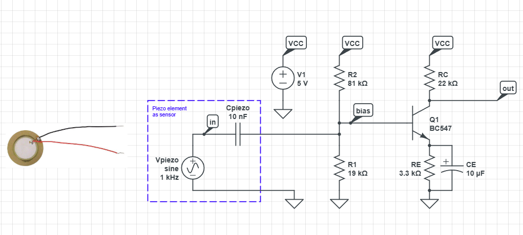
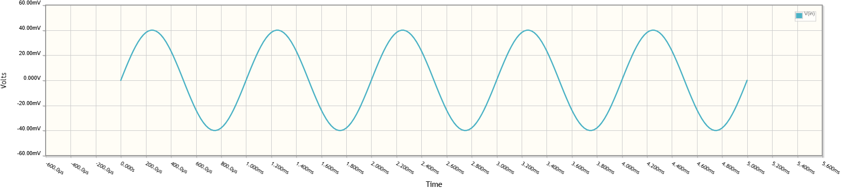
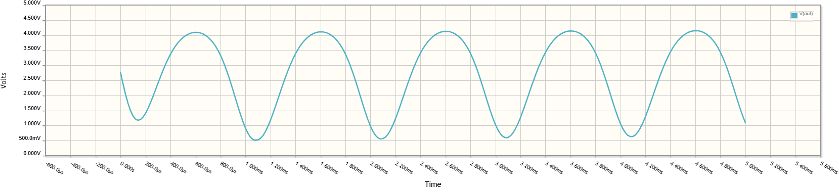
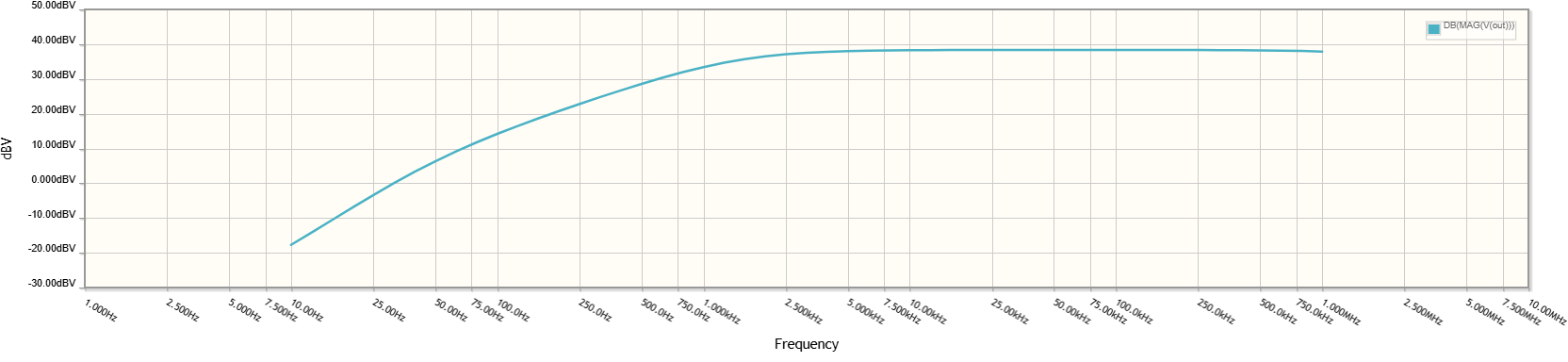
Simulation Results: Audio Amplifier Circuit with BC547
In this section, I have simulated the audio amplifier circuit using BC547. For amplification, BC547 is mostly operated in common emitter configuration. A signal of 40mV is applied at the base terminal of BC547 in a voltage divider bias configuration. The base voltage is calculated in a voltage divider bias configuration as;
\[
V_{b} = V_{CC} \times \frac{R_{2}}{R_{1} + R_{2}}
\]
When a small signal is from a microphone or piezo sensor that produce the sound waves. This is given through a coupling capacitor to the base if BC547 using the voltage divider configuration. The capacitor blocks the DC and only allows the AC signal to pass through. The base voltage provides the voltage that takes the transistor into the active region, which is the amplification region. The small input 40mV signal produces a base current that results in the large collector current as shown in the circuit and output waveform of audio amplifier circuit.
The MAX4411EBE is a IC featuring an 80mW, fixed-gain, DirectDrive, stereo headphone amplifier and is available on flywing tech website.
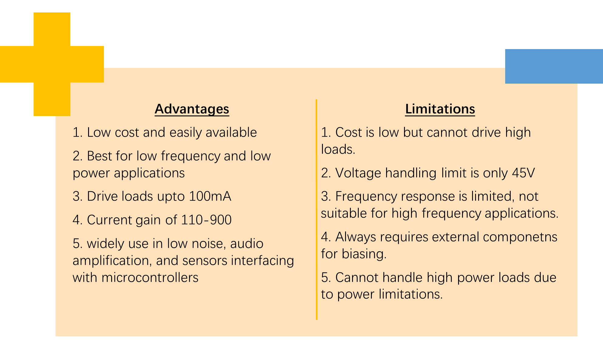
Advantages and Limitations of BC547
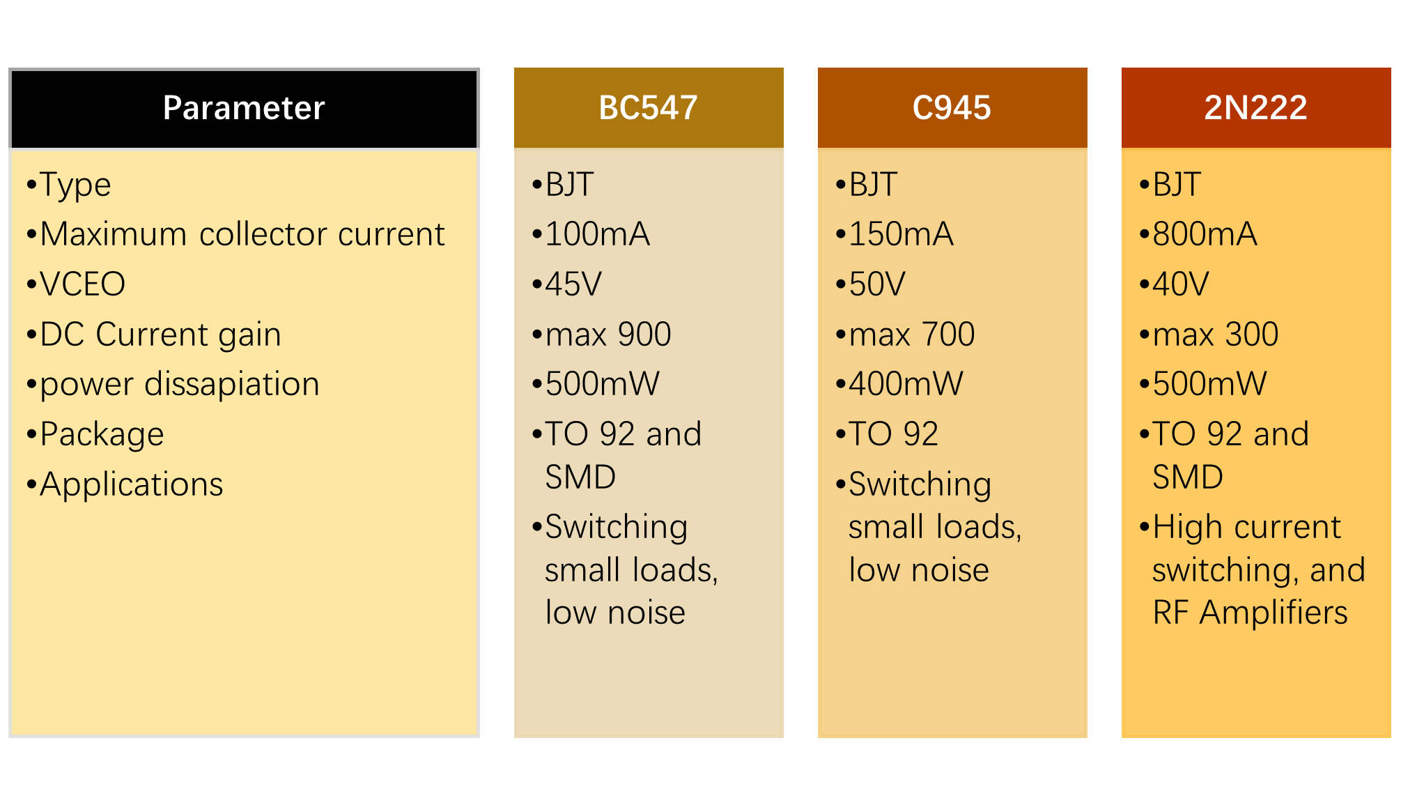
BC547 VS C945 VS 2N2222 Transistors
Conclusion
In conclusion, BC547 is a bipolar transistor that is widely use in low power, low frequency switching, and low noise applications such as sensors interfacing with microcontrollers, relay driving circuits, motor control circuits, and audio signal amplification circuits. Understanding it’s circuit design, its working operation, and its practical circuit design and simulation helps designers and beginners to develop a strong foundation before moving to complex electronic designs.

Frequenctly Asked Questions (FAQ)
Can the BC547 transistor operate with +12V VCC?
Yes, maximum VCEO of BC547 is 45-50V. Therefore, you can operate it with +12V VCC.
Can I use 2N2222 as an alternative to BC547?
Yes, in most of the cases, you can use 2N222 as an alternate to BC547 such as audio amplifiers and switching circuits. However, take care when handling high power circuits because it has 100mA load capability and 2N2222 has maximum of 600mA.
What is the Beta of BC547?
Beta also known as DC current gain of this transistor is typically between 100-900.
Can we use BC547 in a Darlington pair?
To achieve higher current gain, it is common practice to use BC547 in Darlington pair to achieve higher current gain.
What is the difference between BC547 and BC639 transistors?
The basic difference between BC547 and BC639 is that BC547 is low power, general purpose and low noise NPN transistor. Whereas, BC639 is high power NPN transistor with VCEO of 80V and 1A load current.
What are the differences between BC547 BJT and MOSFET IRF740?
The major difference between BC547 and IRF740 is that BC547 is Bipolar transistor and IRF740 is MOSFET family transistor. BC547 is current control device and IRF470 is a voltage control device. The BC547 has only 45V maximum VCEO voltage and IRF470 has VDS (drain to source) voltage is 400V. The BJT transistor BC547 can carry maximum of 100mA loads and IRF470 carry loads up to 10A.