Electronic Component Testing Equipment: What Actually Works
Testing electronic components. Might seem like a broad topic, one that might even seem overwhelming at first glance. Can any single guide actually cover everything you need to know about electronic component testing?
Yes and no.
Yes, in the sense that the principles and techniques you’ll learn here can be applied to testing virtually every type of electronic component you’re likely to encounter in today’s modern circuits, from basic resistors to complex integrated circuits. No, in that it’s impossible to cover every specific testing scenario for the thousands of component variants and specialized devices available today. Covering them all in exhaustive detail would require breaking down the article into several parts.
The focus of this article is on today’s electronic components – the resistors, capacitors, diodes, transistors, and ICs that populate modern circuit boards. These are the components you’ll most commonly need to test, whether you’re troubleshooting a malfunctioning device, verifying parts before installation, or simply learning about electronics fundamentals.
You might think that modern surface-mount components with their tiny packages and densely packed circuits would be impossible to test at home. Fortunately, most component failures occur in our homes, and many testing techniques work just as well on small components as large ones.
What Equipment Do I Need for Electronic Component Testing?
Before diving into specific component testing, you’ll need some basic equipment. The good news is that most of these tools are affordable and readily available.
Which Type of Multimeter Should I Choose: Digital or Analog?
There are two fundamental types: digital and analog. A Digital Multimeter (DMM) displays readings as numbers on a digital screen, while an analog multimeter uses a scale with a moving pointer or needle. You really need to understand both types to handle the full range of testing situations you’ll encounter in component work, though for most home testing, a good digital meter will cover 90% of your needs.
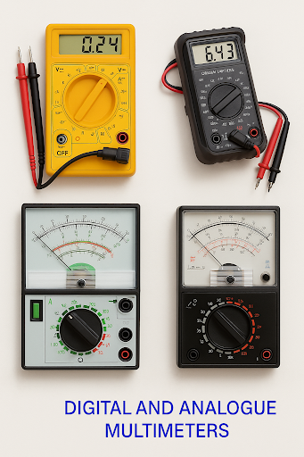
digital vs analog multimeter
How Much Should I Spend on a Multimeter for electronic component testing?
The cost varies dramatically based on features and accuracy. You’ll find basic meters for under $20 and professional units costing hundreds. The price is determined by measurement accuracy, the number of ranges available, and extra features like diode testing, continuity buzzers, transistor testing capabilities, high current measurement, and capacitance measurement.
Since most modern multimeters are reasonably reliable and accurate, focus on getting one with the most useful features at a price point that makes sense for your needs.
Multimeters go by several names – you might hear them called simply “a meter,” a “VOM” (Volt-Ohm-Milliammeter), “multi-tester,” or just “a tester.” They’re all referring to the same basic instrument.
Electronic Component Testing vs Basic Multimeter Readings
Both analog and digital multimeters use either a rotary selector switch or push buttons to choose the appropriate function and measurement range. Many modern DMMs are auto-ranging, meaning they automatically select the correct scale for voltage, resistance, or current measurements. However, you still need to tell the meter what type of measurement you’re making.
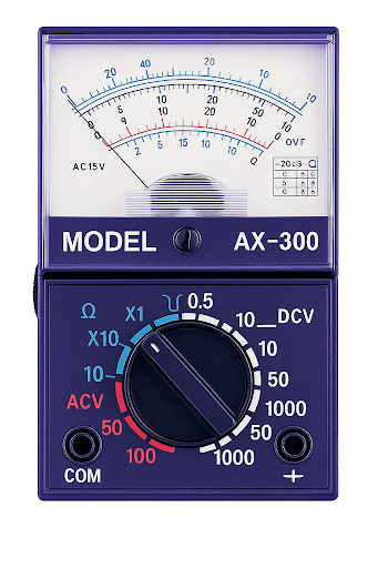
analog meter
What Range Should I Select on My Multimeter?
Before making any measurement, you need to know exactly what you’re testing:
- For voltage measurements: Select either AC ranges (typically 2V, 20V, 200V, 1000V) or DC ranges (usually 200mV, 2V, 20V, 200V, 1000V)
- For resistance: Choose from the ohms ranges (200Ω, 2kΩ, 20kΩ, 200kΩ, 2MΩ, 20MΩ)
- For current measurements: Select the appropriate range (usually 2mA, 20mA, 200mA, 2A, 10A)
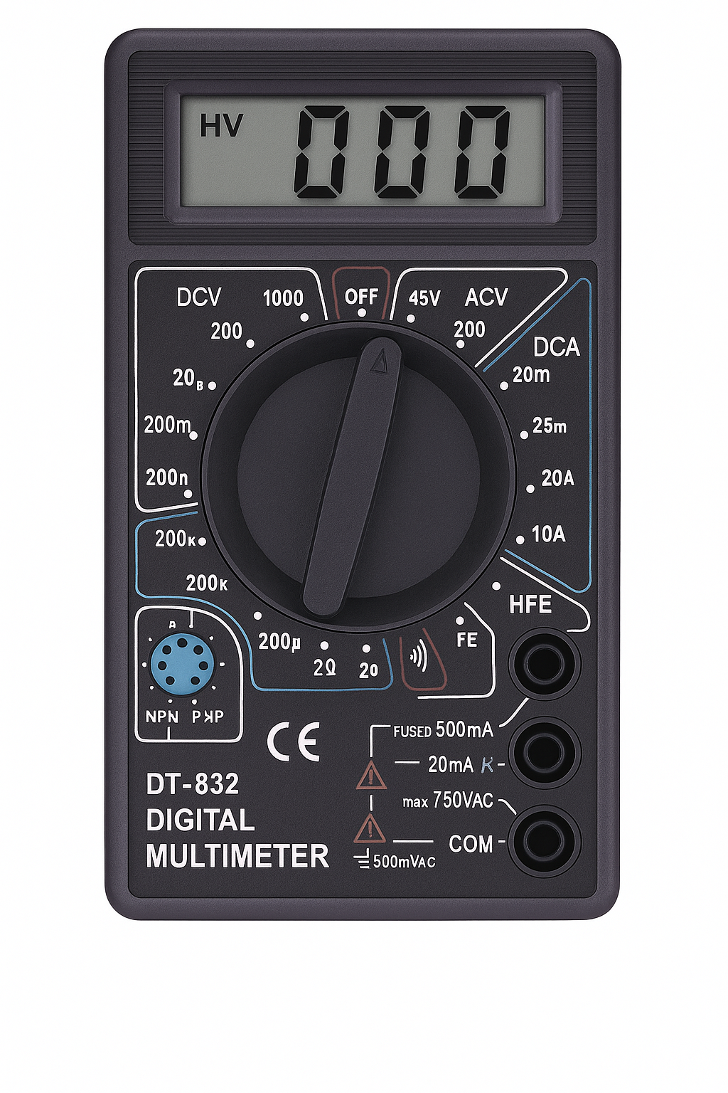
digital meter
The most critical rule: Always select a range higher than your expected maximum value. This prevents the needle from slamming against the end stop on analog meters, which can damage the movement. On digital meters, if you select too low a range, you’ll see “OL” (overload) or “1” flashing on the display, indicating you need to move to a higher range.
Where Do I Connect My Test Leads?
- Black test lead: Always plugs into the socket marked “COM” (common) or with a negative symbol
- Red test lead: Typically goes into the socket marked “VΩmA” for most measurements
- High current measurements: There’s usually a third socket for high current measurements (typically 10A or 20A) – the red lead goes here only when measuring large currents, while the black lead stays in the common socket
Modern test leads have safety guards around both the probe tips and the plugs, allowing you to measure high voltages while maintaining safe distances from live circuits.

multimeter connection
When Should I Use Analog vs Digital Multimeters?
The choice between analog and digital meters often comes down to what you’re trying to observe:
- Digital meters excel at: Precise measurements, exact values, detecting small changes in readings
- Analog meters are better for: Watching trends, observing slowly changing values, detecting intermittent connections – the moving needle makes it easier to spot variations that might be missed on a digital display
Electronic Component Testing: Do I Need to Calibrate My Analog Multimeter?
If you’re working with an analog meter, you’ll need to perform “zero adjustment” before taking resistance measurements. This compensates for battery voltage changes as the internal battery ages:
- Touch the test probes together
- Adjust the “Ohms Adjust” or “Zero Set” control until the needle reads exactly zero ohms (full scale deflection)
- If the pointer won’t reach full scale, it’s time to replace the internal batteries
Electronic Component Testing Accuracy: Avoiding Meter Loading
Digital multimeters don’t require this adjustment procedure.
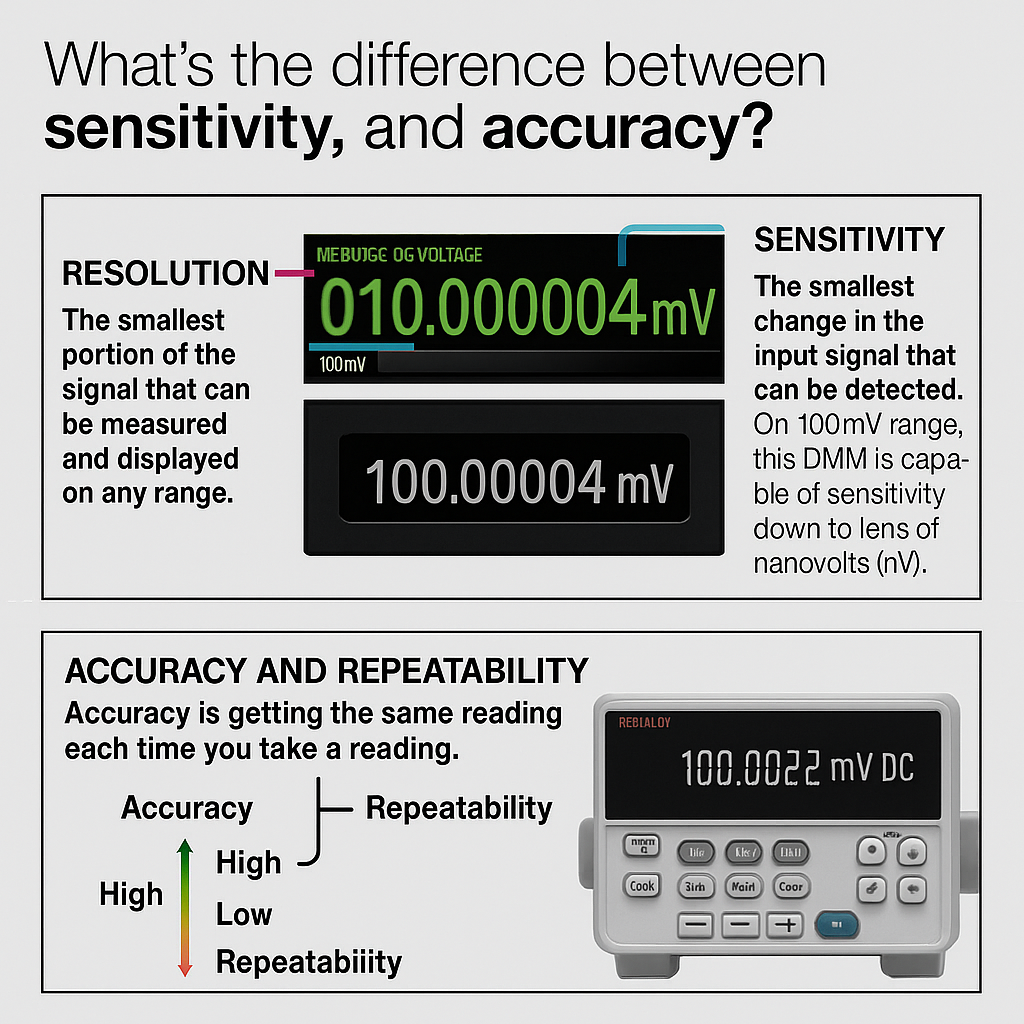
measuring voltage accurately
How Do I Measure Voltage Accurately?
Most of the readings you’ll take with a multimeter will be voltage measurements. This might seem straightforward, but there are several important considerations that can mean the difference between accurate results and completely misleading readings.
What’s the Safest Way to Take Voltage Readings?
Before taking any voltage reading, you should always start with the highest available range and work your way down if needed. If you’re using an analog meter and the needle barely moves (or doesn’t move at all), you can safely select a lower, more sensitive range. Always switch to the highest range before connecting your probes to any circuit – this prevents damage from unexpected high voltages and keeps your fingers safely away from the components being tested.
How Do I Know if I’m Measuring AC or DC Voltage?
For digital multimeters, select the highest voltage range available, or if your meter has auto-ranging capability, simply select “V” and let the meter automatically determine the appropriate range. Many modern DMMs can even automatically detect whether you’re measuring AC or DC voltage, though you may still need to specify this on some models.
- DC voltage: Comes from batteries or regulated power supplies where the voltage remains steady
- AC voltage: Alternates between positive and negative values, typically at 50 or 60 Hz from mains power
Where Should I Connect My Probes for Voltage Measurement?
You can measure voltage in two ways:
Reference Point Method:
- Connect your black probe to the circuit’s reference point – commonly called “chassis,” “earth,” “ground,” or simply “0V”
- Use the red probe to check voltages at any point relative to this reference
- Many circuits include dedicated test points – small loops of wire or accessible pads designed specifically for your probe tip
Across Component Method:
- Connect your probes in parallel with the component – one probe on each side
- This works for measuring voltage drops across transistors, resistors, capacitors, diodes, or inductors
- These component voltages will usually be less than the main supply voltage
Why Are My Voltage Readings Wrong?
Here’s where things get a little bit tricky, and where many component tests go wrong. If you’re measuring voltage in a high-impedance circuit using a cheap analog multimeter, your readings can be off by as much as 90%! This isn’t a small error – it’s enough to completely mislead your troubleshooting efforts.
The Problem: Meter Loading
Consider this example: you have two 1MΩ resistors connected in series between a 10V supply and ground. Basic circuit theory tells us that the voltage at the midpoint should be exactly 5V – half the supply voltage.
But when you connect a cheap analog multimeter set to the 10V range, something unexpected happens. Every analog meter has a sensitivity specification, typically expressed as ohms per volt (Ω/V). A common value is 10,000 Ω/V, which means on the 10V range, the meter’s internal resistance is 100,000 Ω.

measuring voltage in circuit
What Actually Happens:
When you connect that 100kΩ meter across the lower 1MΩ resistor, you’ve created a parallel resistance circuit. The meter’s 100kΩ internal resistance is now in parallel with the 1MΩ resistor you’re trying to measure across.
Using parallel resistance calculations: 1/Total = 1/1MΩ + 1/100kΩ = approximately 91kΩ
Now instead of having 1MΩ + 1MΩ in series (which would give you 5V at the midpoint), you effectively have 1MΩ + 91kΩ in series. This completely changes the voltage division, and your meter will read less than 1V instead of the expected 5V!
Why Are Digital Multimeters Better for Voltage Measurement?
This is one of the significant advantage of digital multimeters (DMM). Most DMMs have input impedances of 10 MΩ or higher – typically 10 MΩ or even 100 MΩ. When you connect a 10 MΩ meter across a 1 MΩ resistor, the parallel combination is approximately 909kΩ – much closer to the original 1 MΩ, resulting in far more accurate readings.
What Does Meter Loading Mean for My Component Testing?
This loading effect is crucial to understand when testing components in high-impedance circuits. It explains why:
- Bias voltage measurements on high-gain transistor circuits can be misleading with cheap meters
- Voltage references and precision circuits require high-impedance meters for accurate readings
- Some “faulty” components might actually be fine – the meter itself is changing the circuit behavior
The lesson here is, For accurate voltage measurements in high-impedance circuits, invest in a quality digital multimeter with high input impedance. Your troubleshooting accuracy depends on it.
How Do I Measure Current Safely?
You’ll rarely need to take current measurements during routine component testing, but when you do, these measurements can provide invaluable diagnostic information. Most multimeters offer DC current ranges such as 2mA, 20mA, 200mA, and 2A or 10A (typically through a separate high-current input socket), and some meters also include AC current measurement capabilities.
What Can Current Measurements Tell Me?
Current measurements tell you things that voltage and resistance measurements cannot. If you know the normal operating current for a circuit or component, discovering unusually high or low current can immediately point you toward the problem:
- High current often indicates: Short circuit, overloaded component, or failed part drawing excessive power
- Low current might suggest: Open circuit, failing component, or circuit not operating at full capacity
What’s the Difference Between Current and Voltage Measurement Setup?
Here’s the most important concept to understand about current measurement: current must always be measured with the circuit powered and operating, and the meter must be connected in series with the circuit or component under test. This is fundamentally different from voltage measurement, where you connect the meter in parallel with the component.
Think of current as water flowing through a pipe – to measure the flow, you need to put your flow meter directly in the path of the water. Similarly, to measure electrical current, you need to create an opening in the circuit and insert your meter into that opening, forcing all the current to flow through the meter.
Electronic Component Testing: How Do I Create a Series Connection for Current Measurement?
Easy Methods:
- Remove the fuse and take your reading across the fuse holder – this automatically creates the series connection you need
- Disconnect one battery lead or turn off the main power switch and measure across the switch contacts
When No Convenient Break Points Exist:
- Remove one end of a component – resistors are usually the easiest to desolder since they’re not polarity-sensitive
- In some cases, you might need to cut a printed circuit track to create the necessary break (last resort since it requires repair afterward)

common mistakes in measuring current
What’s the Most Dangerous Mistake in Current Measurement?
Never attempt to measure current by connecting your meter across a component – this creates a direct short circuit that can damage components, blow fuses, or even cause dangerous conditions.
Why This Is So Critical:
When you connect a current meter across a component (the wrong way), you’re essentially placing a very low-resistance path in parallel with that component. Since the meter’s internal resistance for current measurement is typically less than 1 ohm, nearly all circuit current will flow through your meter instead of through the component. This can:
- Starve the component of its normal operating current
- Send excessive current through other parts of the circuit
- Apply voltages to circuit sections that aren’t designed to handle them
- Damage both your meter and the circuit under test
The component you’re trying to test is designed to drop a specific voltage while allowing current to flow through it. When you place your current meter across the component, you’re creating a “jumper wire” that bypasses the component entirely.
What Should I Remember About Current Measurement Setup?
For current measurements, you typically need to:
- Move your red test lead to the current input jack on your multimeter (often marked “A” or “mA”)
- Always start with the highest current range to prevent blowing internal fuses
- Use separate high-current jacks (usually 10A or 20A) that bypass the meter’s internal current-limiting fuses for safety when measuring large currents
What’s Coming in Part 2?
We’ve covered the fundamental principles of electronic component testing, focusing on the essential skills you need to measure voltage and current accurately. These basic measurements form the foundation of all component testing work, and understanding concepts like meter loading and series versus parallel connections will save you countless hours of troubleshooting frustration.
But this is just the beginning. In Part 2 of our DIY Component Testing Guide, we’ll dive deeper into testing specific components that make up the heart of modern electronics. You’ll learn the hands-on techniques for testing resistors, capacitors, diodes, transistors, and integrated circuits.
Stay tuned for Part 2, where we’ll put these measurement principles to work testing real components!
Quick Reference Glossary
AC (Alternating Current) – Electrical current that periodically reverses direction, typically from mains power supplies
Auto-ranging – Feature that automatically selects the appropriate measurement range
COM – Common terminal on a multimeter, where the black (negative) test lead connects
DC (Direct Current) – Electrical current that flows in one direction only, such as from batteries
DMM – Digital Multimeter
ESR – Equivalent Series Resistance, particularly important in capacitor testing
Ground/Earth/Chassis – The reference point (0V) in a circuit
hFE – Current gain specification for bipolar transistors
Input Impedance – The internal resistance of a measuring instrument
Loading Effect – When a meter’s internal resistance affects the circuit being measured
OL – Overload indication on digital meters, meaning the measurement exceeds the selected range
Parallel – Connected across a component (voltage measurements)
Series – Connected in line with current flow (current measurements)
VOM – Volt-Ohm-Milliammeter, another name for a multimeter
VΩmA – Common marking on multimeter input jacks for voltage, resistance, and milliamp measurements
Join the Conversation
We’d love to hear about your component testing experiences! What’s the most challenging component failure you’ve diagnosed at home? Have you discovered any clever testing tricks or made any costly mistakes that taught you valuable lessons?
Share your stories in the comments below – your experience might help fellow electronics enthusiasts avoid common pitfalls or inspire new testing approaches. Whether you’re a beginner just starting out or a seasoned pro with years of troubleshooting under your belt, the electronics community thrives on shared knowledge and practical wisdom.
What component testing topics would you like us to cover in Part 2? Let us know what specific components or testing scenarios you’d find most helpful!