When working with microcontrollers or digital logic circuits, you will often encounter a common limitation: GPIO pins cannot directly drive high-current devices. This is where the ULN2803 Darlington transistor array becomes extremely useful.
According to Texas Instruments, the ULN2803C is an 8-channel 50 V, 500 mA Darlington transistor array with common-cathode clamp diodes for switching inductive loads.
It allows low-power logic signals to control higher-power loads.
Each channel inside the chip contains a Darlington transistor pair, enabling the IC to switch loads that operate at voltages up to 50 V and currents up to 500 mA per channel.
Because of this capability, engineers widely use the ULN2803 in embedded systems and control circuits. Engineers frequently use it to interface microcontrollers, logic ICs, and shift registers with external devices
In the following sections, we will explore how the ULN2803 works, its pinout, internal structure, and practical circuit applications so you can confidently use this IC in your own designs.
What Is a ULN2803 Darlington Transistor Array?
A Darlington transistor array is an integrated circuit that contains multiple Darlington transistor pairs in a single package.
These arrays amplify current and switch higher-power loads by using low-power control signals from logic devices.
The ULN2803 is a common example. It integrates eight NPN Darlington pairs, allowing one IC to control multiple loads such as relays, motors, or LED displays.
Each channel acts as a switching stage that digital logic can drive directly while handling significantly higher output currents.
A Darlington pair itself consists of two bipolar transistors connected so that the current amplified by the first transistor is amplified again by the second.
This configuration produces very high current gain, meaning a small input current can control a much larger load current.
Darlington arrays simplify driver circuit design because they combine several components into one chip. In devices like the ULN2803, each channel typically includes the Darlington pair, input resistors for logic compatibility, and protection diodes for inductive loads.
This reduces the need for discrete transistors and extra components, making multi-channel driver circuits easier to design and implement.
ULN2803 Key Features
The ULN2803 Darlington transistor array simplifies high-current switching in digital and embedded systems.
By integrating multiple driver stages into one IC, it allows logic circuits to control external loads without requiring additional discrete transistors.
These key features make the ULN2803 IC popular in electronics projects and industrial control systems:
| Feature | Description |
| 8 Driver Channels | The IC contains eight independent Darlington transistor drivers, allowing multiple loads to be controlled from one chip. |
| High Output Voltage | Each channel can handle load voltages up to 50 V, making it suitable for many control applications. |
| High Current Capability | Each output can sink up to 500 mA, enabling the IC to drive devices like relays, solenoids, and motors. |
| Built-in Flyback Diodes | Integrated clamp diodes protect the circuit from voltage spikes caused by inductive loads. |
| TTL / CMOS Compatible Inputs | The inputs are designed to work directly with microcontrollers, logic ICs, and shift registers. |
| Open-Collector Outputs | Outputs act as low-side switches, allowing flexible connection to different load voltages. |
Because of these features, the ULN2803 driver IC is commonly used when a microcontroller needs to interface with higher-power devices.
Instead of designing separate transistor driver circuits for each output, engineers can use a single ULN2803 to control several loads efficiently.
ULN2803 Pinout and Pin Configuration
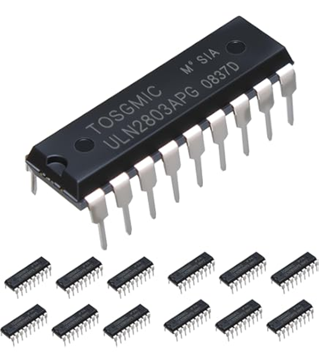
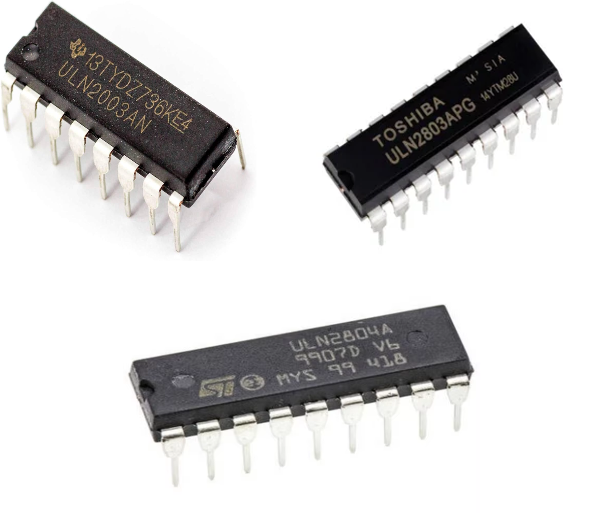
Manufacturers typically offer the ULN2803 IC in an 18-pin package (DIP or SOIC).
The pins are arranged so that the inputs are on one side and the corresponding outputs are directly opposite, which simplifies PCB routing when connecting loads.
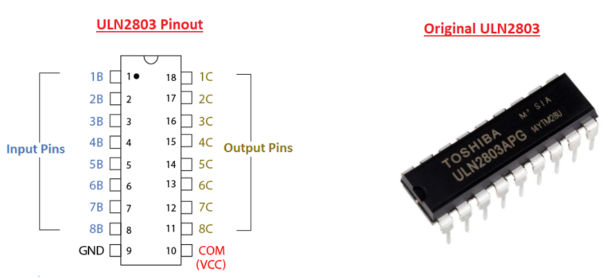
The device contains eight driver channels, meaning each input pin controls a corresponding output pin.
When a logic signal reaches an input, the associated Darlington pair switches the output and allows current to flow through the connected load.
| Pin | Name | Description |
| 1–8 | IN1–IN8 | Logic input pins used to control each driver channel. You can connect these directly to microcontrollers, logic ICs, or shift registers. |
| 9 | GND | Ground connection for the IC and the reference for all driver circuits. |
| 10–17 | OUT1–OUT8 | Output pins connected to the collectors of the Darlington transistors. These pins sink current from the load. |
| 18 | COM | Common diode connection used for the internal flyback diodes when driving inductive loads. |
Each input pin controls the corresponding output pin. For example:
- IN1 controls OUT1
- IN2 controls OUT2
- and so on through all eight channels.
When a logic HIGH signal reaches an input, the Darlington pair turns on and the corresponding output pulls the load to ground, allowing current to flow through the load
The COM pin plays an important role when you drive inductive loads such as relays or motors. It connects the internal clamp diodes to the supply voltage, so the diodes can safely redirect switching spikes and help protect the driver IC.
Because of this straightforward pin arrangement, the ULN2803 pinout makes it easy to interface digital control signals with multiple high-current loads in a compact circuit design.
Internal Structure of the ULN2803
The ULN2803 integrates multiple driver stages into a single IC. Internally, the chip contains eight identical channels, each designed to switch higher-current loads using low-power logic signals.
Each channel includes three main elements:
- Darlington transistor pair
- Input resistor network
- Clamp (flyback) diode
The Darlington pair forms the core of the driver stage. Designers connect two NPN transistors so that the first transistor amplifies the current and the second transistor amplifies it again.
This arrangement provides very high current gain, allowing small input currents from logic devices to control much larger load currents.
The IC includes the input resistor and connects it to the base of the first transistor. This resistor limits base current and lets designers connect the input pins directly to TTL or CMOS logic outputs such as those from microcontrollers or digital ICs.
The output stage uses an open-collector configuration. In this arrangement, the Darlington pair’s collector connects to the output pin while its emitter connects to ground.
When the input signal activates the transistor pair, the output pin pulls to ground and current flows through the external load.
Each channel also includes a clamp diode connected to the COM pin. These diodes provide protection when driving inductive loads like relays, motors, or solenoids.
When those loads switch off, they can generate high-voltage spikes. The internal diodes safely redirect this energy back to the supply line.
Because all eight channels share the same design, the ULN2803 internal structure enables reliable multi-channel switching while keeping the external circuit simple and compact.
ULN2803 Electrical Specifications
The electrical characteristics of the ULN2803 Darlington transistor array determine the types of loads it can drive and the environments in which it can operate.
| Parameter | Typical Value |
| Output Voltage (Collector-Emitter) | Up to 50 V |
| Maximum Output Current (per channel) | 500 mA |
| Peak Output Current | 600 mA |
| Number of Channels | 8 |
| Input Compatibility | TTL / CMOS |
| Operating Temperature Range | −20°C to +85°C (typical commercial range) |
While each channel can handle up to 500 mA, designers must also consider the total current through the IC to prevent excessive heat buildup.
In many designs, engineers limit the continuous current per channel to ensure safe thermal operation.
Another characteristic of Darlington drivers is the collector-emitter saturation voltage, which is typically around 1 V to 1.3 V when the transistor is conducting.
Designers should consider this voltage drop when they calculate load voltage and power dissipation.
Understanding these specifications helps designers determine whether the ULN2803 IC is suitable for a particular load or control system.
Readers comparing package and sourcing options can also check ULN2803AN variants available on Flywing Tech.
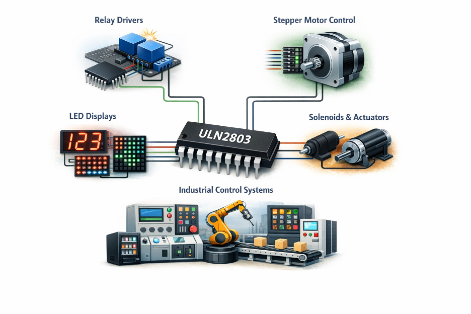
Typical ULN2803 Circuits
Engineers widely use this configuration in home automation systems, PLC interfaces, and microcontroller-based control boards.
Because each channel functions as a low-side switch, the IC can easily interface with a variety of devices used in embedded systems and industrial control.
Below are some of the most common ULN2803 circuit applications.
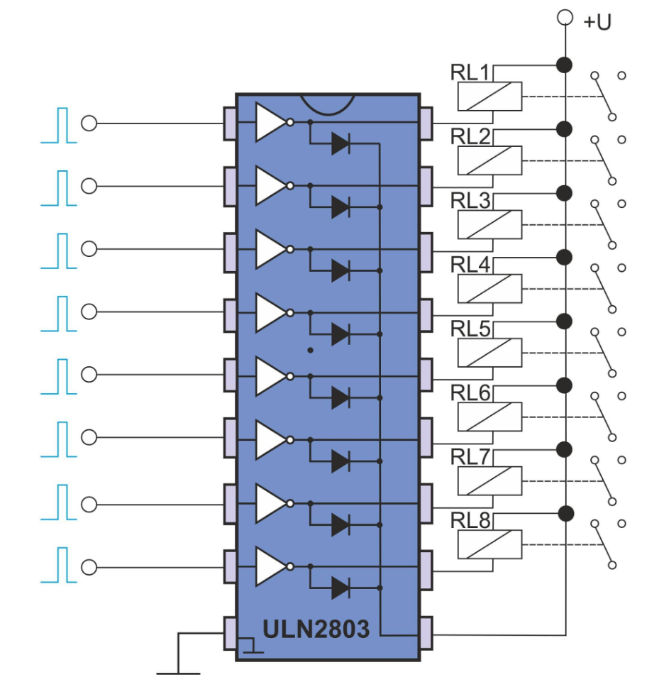
Relay Driver Circuit
One of the most frequent uses of the ULN2803 relay driver is controlling relay coils from a microcontroller or logic circuit.
In this configuration:
- One side of the relay coil connects to the supply voltage.
- The other side connects to the ULN2803 output pin.
- The corresponding input pin connects to a microcontroller GPIO.
- The COM pin connects to the relay supply voltage so the internal flyback diodes can suppress voltage spikes.
When the input receives a HIGH signal, the driver channel turns on and the relay coil is energized. When the signal goes LOW, the relay turns off.
This configuration is widely used in home automation systems, PLC interfaces, and microcontroller-based control boards.
Stepper Motor Driver Interface
The ULN2803 is frequently used with unipolar stepper motors, especially in small embedded systems.
You can connect each motor winding to a separate output channel of the driver IC.
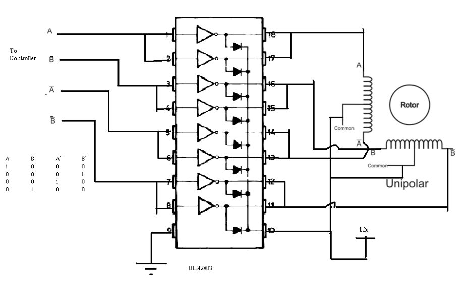
A microcontroller or stepper control circuit sends pulse sequences to the ULN2803 inputs, which switch the motor coils in the required order.
Because the driver can sink higher current than the controller itself, it allows reliable motor operation without stressing the microcontroller pins.
The ULN2803 is frequently used with unipolar stepper motors, especially in small embedded systems. For a closely related driver example, see ULN2003 pinout, sequences, and drive modes
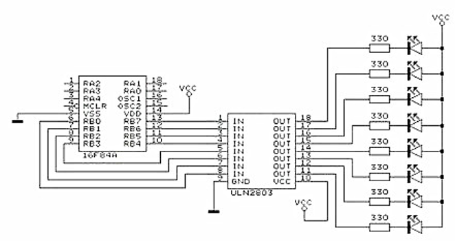
LED Display and LED Matrix Driver
LED arrays and display modules often require more current than logic outputs can provide. The ULN2803 LED driver configuration allows multiple LEDs or LED segments to be controlled simultaneously.
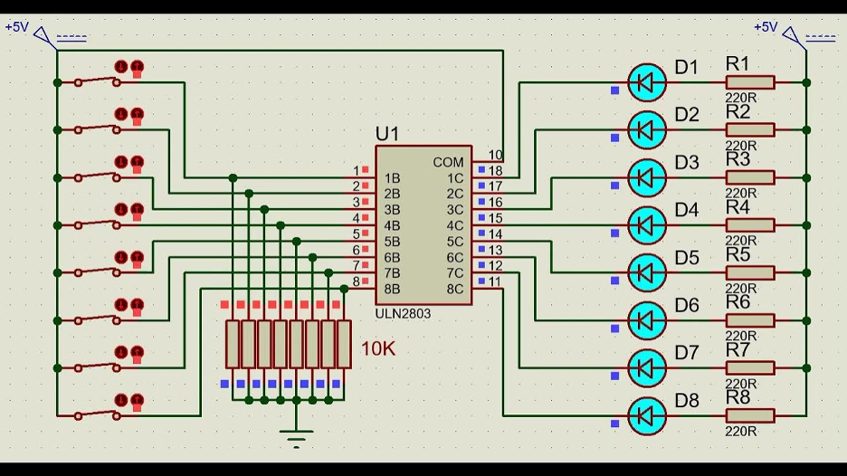
For example:
- A microcontroller or shift register controls the input pins.
- The outputs sink current through LED rows or columns.
- External resistors limit LED current.
Engineers commonly use this approach in LED matrices, seven-segment displays, and digital signage circuits.
Solenoid and Actuator Control
Small solenoids and electromagnetic actuators require higher current to operate reliably. The ULN2803 solenoid driver circuit lets digital logic systems control these devices safely.
When the input signal activates a channel, the output sinks current through the solenoid coil, generating the magnetic field needed to move the actuator.
The internal clamp diodes help protect the circuit from inductive voltage spikes when the device turns off.
Because the IC provides eight driver channels in one package, it is particularly useful in applications where several actuators or loads must be controlled from a single controller.
ULN2803 vs ULN2003 vs ULN2804
The ULN2803 belongs to a family of Darlington transistor array driver ICs that also includes devices such as the ULN2003 and ULN2804. These ICs share a similar internal structure but differ in the number of channels and input resistor configurations.
Understanding these differences helps designers select the correct driver IC for a particular logic system.
| Feature | ULN2003 | ULN2803 | ULN2804 |
| Number of Channels | 7 | 8 | 8 |
| Package | 16-pin | 18-pin | 18-pin |
| Output Voltage | Up to 50 V | Up to 50 V | Up to 50 V |
| Output Current (per channel) | 500 mA | 500 mA | 500 mA |
| Input Compatibility | TTL | TTL / CMOS | High-voltage CMOS |
The ULN2003 contains seven driver channels and is commonly used with devices such as 7-segment displays and unipolar stepper motors.
It is often found in stepper motor driver boards, especially those used with small motors like the 28BYJ-48.
The ULN2803, on the other hand, includes eight channels.
Because of its built-in input resistors and TTL compatibility, it works well with microcontrollers, shift registers, and logic circuits.
The ULN2804 is similar to the ULN2803 but targets systems that use higher input voltages such as 6–15 V CMOS logic levels.
ULN2803 vs MOSFET Driver Solutions
Although we use ULN2803 Darlington transistor array in driver circuits, modern designs sometimes use MOSFET-based drivers instead.
Both approaches allow microcontrollers and logic circuits to control higher-current loads, but they differ in efficiency, switching behavior, and design complexity.
The ULN2803 uses Darlington transistor pairs, which provide high current gain but introduce a noticeable voltage drop across the output transistor.
MOSFET drivers, on the other hand, typically have much lower conduction losses. If you want a simple discrete MOSFET example, see IRFZ44N MOSFET guide.
| Parameter | ULN2803 (Darlington Array) | MOSFET Driver |
| Switching device | Bipolar Darlington transistors | MOSFETs |
| Voltage drop | Higher (≈1–1.3 V) | Very low |
| Efficiency | Moderate | Higher |
| Circuit complexity | Very simple | Slightly higher |
| Cost | Very low | Usually higher |
| Ease of use | Plug-and-play driver IC | May require additional components |
Because of the higher saturation voltage of Darlington transistors, some power is dissipated as heat when the ULN2803 is driving larger loads.
For low- to medium-power applications such as relay boards, LED displays, and small motors, this is usually not a significant issue.
MOSFET drivers become more attractive in situations where:
- High efficiency is required
- Load currents are large
- Power dissipation must be minimized
Despite these advantages, the ULN2803 remains popular in many embedded systems because it is inexpensive, easy to use, and integrates eight driver channels along with protection diodes in one IC.
For many control applications, this simplicity makes the ULN2803 a practical and reliable choice.
Real-World Applications of the ULN2803
Engineers widely use the ULN2803 Darlington transistor array in electronic systems where low-power digital signals must control multiple higher-current devices.
Relay Driver Circuits
One of the most common uses of the ULN2803 relay driver is controlling relay coils from microcontrollers or logic circuits.
Microcontroller GPIO pins cannot supply the current required by relay coils, but the ULN2803 can safely switch these loads.
In this configuration, the relay coil connects to the supply voltage, and the ULN2803 output sinks current to ground when activated.
The internal clamp diodes protect the circuit from voltage spikes generated when the relay coil is switched off.
Stepper Motor Control
The ULN2803 is frequently used to drive unipolar stepper motors in small automation and robotics applications.
Each motor winding is connected to a driver channel, while the microcontroller sends pulse sequences to the input pins.
This setup allows the controller to energize motor coils in the required order while the ULN2803 handles the current required by the motor windings.
LED Display and LED Matrix Drivers
Large LED displays and LED matrices often require more current than logic outputs can handle.
The ULN2803 LED driver configuration allows digital circuits to control multiple LEDs or display segments simultaneously.
The IC sinks current through LED rows or columns while external resistors limit the LED current.
Engineers use this approach in in seven-segment displays, LED matrices, and digital signage systems.
Solenoids and Electromechanical Actuators
Many industrial and control systems use solenoids and electromagnetic actuators that require higher current to operate.
The ULN2803 can switch these devices safely while protecting the control circuit.
The internal clamp diodes are particularly important in these applications because inductive loads generate voltage spikes when switched off.
Embedded and Industrial Control Systems
Designers use ULN2803 driver IC in embedded control systems that need to operate multiple external devices. Typical examples include:
- Control panels and automation systems
- Printer mechanisms and electromechanical drivers
- Vending machines and appliance control boards
- Microcontroller-based control modules
Because it combines multiple driver stages, protection diodes, and logic-compatible inputs in a single device, the ULN2803 provides a simple and reliable solution for multi-channel load control.
ULN2803 Alternatives
Several alternative devices and driver solutions are also available. The choice often depends on factors such as current requirements, efficiency, switching speed, and system voltage.
ULN2003
The ULN2003 is one of the closest alternatives to the ULN2803. It uses the same Darlington driver architecture but includes seven output channels instead of eight.
Because of its similar functionality, engineers commonly use the ULN2003 in stepper motor driver boards.
For applications that require fewer channels, it provides a compact and inexpensive solution.
ULN2804
The ULN2804 is very similar to the ULN2803 but for higher input voltage logic systems. It includes different input resistor values that make it suitable for 6 V to 15 V CMOS logic levels.
This makes the ULN2804 useful in industrial or legacy digital systems where control signals operate at higher voltages than typical microcontroller logic levels.
MOSFET Driver Arrays
In some modern designs, engineers replace Darlington arrays with MOSFET-based driver ICs or discrete MOSFET circuits.
MOSFET drivers typically offer:
- Lower voltage drop
- Higher efficiency
- Reduced power dissipation
Because of these advantages, engineers prefer MOSFET drivers when switching high-current loads or power-sensitive systems.
Shift Register Drivers
Another alternative in multi-output control systems is using shift registers with built-in drivers, such as devices designed for LED arrays or high-current outputs.
Designers often use these solutions when a system needs to control many outputs with a limited number of microcontroller pins.
Despite these alternatives, the ULN2803 remains a popular driver IC because of its simplicity, low cost, and ability to control multiple loads directly from standard logic signals without requiring complex external circuitry.
Final Thoughts
The ULN2803 Darlington transistor array remains one of the most practical solutions for interfacing low-power logic circuits with higher-current loads.
With eight integrated driver channels, built-in base resistors, and flyback protection diodes, the IC significantly simplifies the design of multi-channel driver circuits.
For engineers and embedded developers, the ULN2803 offers several advantages:
- Direct compatibility with microcontrollers and digital logic
- Ability to control multiple loads from a single IC
- Built-in protection for inductive devices such as relays and motors
- A simple and reliable low-side switching architecture
Because of these features, engineers commonly use the ULN2803 driver IC when a microcontroller needs to interface with higher-power devices.
Even with modern alternatives like MOSFET drivers available, the ULN2803 remains popular due to its low cost, simplicity, and proven reliability in many control applications.
When designing circuits that require reliable driver stages, selecting high-quality electronic components is equally important.
Engineers can source Darlington driver ICs, transistors, connectors, and supporting components from trusted electronics suppliers such as Flywing Tech. We can provides a wide range of parts used in embedded systems, automation electronics, and hardware development.
ULN2803 FAQs
What is the ULN2803 used for?
Engineers use the ULN2803 Darlington transistor array to drive higher-current loads from low-power logic circuits. It is commonly used to control devices such as relays, stepper motors, solenoids, LED displays, and lamps using microcontrollers or digital logic ICs.
Can the ULN2803 drive a relay?
Yes, the ULN2803 is widely used as a relay driver. Each output channel can sink up to 500 mA, which is sufficient for many relay coils. The IC also includes built-in flyback diodes, which protect the circuit from voltage spikes generated when the relay coil is switched off.
Can ULN2803 work with Arduino or other microcontrollers?
Yes. The ULN2803 is compatible with TTL and CMOS logic, so you can connect it directly to microcontroller GPIO pins on Arduino, PIC, STM32, and AVR boards.
What is the difference between ULN2803 and ULN2003?
The main difference is the number of driver channels. The ULN2803 contains eight driver outputs, while the ULN2003 provides seven channels and typically comes in a 16-pin package. Both ICs use Darlington transistor arrays and have similar current and voltage ratings.
Can ULN2803 drive a motor?
Yes, the ULN2803 can drive small DC motors or unipolar stepper motors, provided the current requirements stay within the IC’s limits. Engineers commonly use it in stepper motor driver circuits where multiple outputs energize motor windings.
What is the maximum current of ULN2803?
Each output channel of the ULN2803 can handle up to 500 mA of continuous current. However, designers should consider the IC’s total current and power dissipation when multiple outputs are active at the same time.