Introduction
Electrical Connectors serve as the physical and electrical link between components, whether you are prototyping with an Arduino board, designing an industrial controller, or wiring a power module.
As electronics become more compact and multifunctional, the demand for specialized connectors grows.
According to market data, the global cable connector Market was valued at USD 73.01 billion in 2025 and is expected to reach USD 100.07 billion by 2034, at a CAGR of 3.23% during the forecast period 2025-2034.
Moreover, robotics, electric vehicles, and embedded electronics all use high-performance connectors, among the fastest-growing segments worldwide.
This guide offers a clear overview of electrical connectors from basic classifications like board-to-wire and board-to-board, to widely used standards such as USB, HDMI, RJ45, and Molex.
You’ll learn how different connector types function, where they are used, and how to select the right one based on power, size, environment, and application needs.
What Are Electrical Connectors?
Electrical connectors are components designed to join electrical circuits and allow for quick and secure connection or disconnection of those circuits without the need for permanent methods like soldering.
They enable scalable designs, repairability, and flexible assembly across various electronic and electrical systems.
Connectors come in many forms, but they generally fall into two main categories:
- One-piece connectors: These directly interface wires or printed circuit boards (PCBs) without requiring a counterpart.
- Two-piece connectors: These consist of a plug and a socket, designed to mate and unmate repeatedly. The area where the plug and socket join is called the contact interface, while the area connected to the wire or PCB is referred to as the termination point or connection interface.
Electrical connectors can be engaged or disengaged by hand or with simple tools, making them ideal for everything from consumer electronics to industrial automation systems.
Types of Electrical Connectors
Electrical connectors play different roles depending on how they link components within an electronic system.
You can design modular PCBs, connect external devices, or manage signals and power across enclosures using the right connector.
Let’s talk about different types of electrical connectors:
Board-to-Board Electrical Connectors
These connectors stack or connect multiple printed circuit boards (PCBs) in a compact layout. In embedded systems, they allow signal and power transmission without extra wiring.
This makes them particularly useful for shielding microcontrollers or backplane-based assemblies.
Common examples include:
- Pin headers and sockets (male/female)
- Mezzanine connectors
- Backplane connectors
FlyWing’s nylon board connector is a typical example of a board‑to‑board housing that withstands –40 °C to 105 °C, ideal for embedded module stacking.
Board-to-Wire Electrical Connectors
Designed to link individual wires to a PCB, these connectors are essential in bringing power and signal lines from external modules like sensors, motors, or battery packs into the board.
Additionally, they offer secure, often removable connections, making them ideal for modular builds or devices that require occasional disconnection or maintenance.
Common examples include:
- Crimp terminals
- Locking wire harnesses
- Screw terminal blocks
Input/Output (I/O) Electrical Connectors
I/O connectors form the physical interface between a device and the outside world. They are used to connect peripherals such as computers, audio systems, or network hardware.
Reliable I/O connectivity is also essential for smooth communication and user interaction in consumer electronics and industrial applications.
Common examples include:
- Serial and USB ports
- Audio jacks
- Ethernet (RJ45) connectors
Modular and Plug-In Electrical Connectors
These connectors are built for flexibility, allowing users to plug, unplug, or replace components without tools easily.
They’re often used in development boards, modular systems, or power supplies where quick access or reconfiguration is necessary.
Their design also supports hot-swapping in many cases, which reduces downtime.
Common examples include:
- Card-edge slots
- Pluggable terminal blocks
- Breakaway headers
Specialty and Miscellaneous Electrical Connectors
This category includes connectors that serve niche roles or specialized functions, often in testing, programming, or radio frequency (RF) systems.
These components may not be as standard as board-to-board or I/O connectors, however are crucial in professional electronics design, especially where space constraints or signal integrity are critical.
Common examples include:
- IC sockets (DIP, SOP)
- Jumper caps and shunts
- RF connectors (SMA, BNC)
Common Standards You Should Know
Electrical connectors are more than just mechanical links. They define how power, signals, and data are transmitted across components and systems.
You need to understand connector standards to ensure compatibility, performance, and reliability in your electronic design. Lets talk about some common standards:
USB: Type-A, Type-B, Micro, and Type-C
USB (Universal Serial Bus) connectors are widely used in embedded and consumer electronics for communication, programming, and power delivery.

- USB Type-A: The standard rectangular connector found on computers, chargers, and many development boards like the Arduino Uno.
- USB Type-B: A square-shaped connector on older printers, scanners, and Arduino Mega boards.
- Mini-USB & Micro-USB: Smaller versions used in compact electronics, including older smartphones and cost-effective development boards.
- USB Type-C: A compact, reversible connector supporting high-speed data transfer and fast charging.
Typical Applications include microcontroller programming, power supply (5V), USB-based serial communication, firmware updates, and HID device interfacing.
Check out USB connectors here if you’re looking for the best ones.
RJ45 (Ethernet)
RJ45 connectors are standardized 8P8C modular plugs used for wired networking. They are essential in devices requiring stable data transfer, such as embedded Ethernet modules or industrial automation systems.
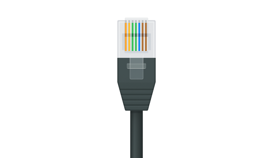
- Support for 10/100/1000 Mbps Ethernet
- Typically used with CAT5e or CAT6 cables
- Found in industrial IoT setups and programmable logic controllers (PLCs)
Typical applications include Local area network (LAN) connections for Raspberry Pi, Ethernet-enabled Arduino boards (e.g., with W5100/W5500 shields), and SCADA systems.
DIN and Mini-DIN
DIN connectors, are round multi-pin connectors used in audio, instrumentation, and industrial communication.
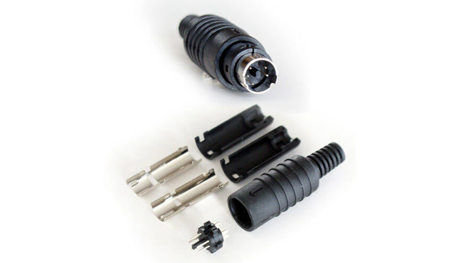
- 5-pin DIN: Popular in vintage audio systems and MIDI instruments
- 8-pin and higher DIN: Utilized in motion control, robotics, and harsh environments
- Mini-DIN: Seen in older peripherals like PS/2 keyboards and mice, and still relevant in robotics
Typical applications includes audio interfaces, MIDI controllers, CNC communication, and rugged industrial environments
HDMI and DisplayPort
Both HDMI and DisplayPort are digital video/audio interfaces used to transmit high-quality signals between embedded boards and displays.
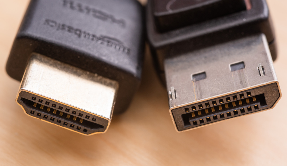
- HDMI: Widely adopted in Raspberry Pi, digital signage systems, and consumer AV devices. It combines video and audio over a single cable.
- DisplayPort: Supports higher resolutions and refresh rates. More common in high-performance computing and advanced monitors.
Typical applications include media centers, visual monitoring systems, camera interfaces, and embedded video applications.
Molex, JST, and IDC
These internal connector standards are used extensively within consumer devices, embedded systems, and power modules.
They each offer specific strengths in size, current capacity, and ease of assembly.
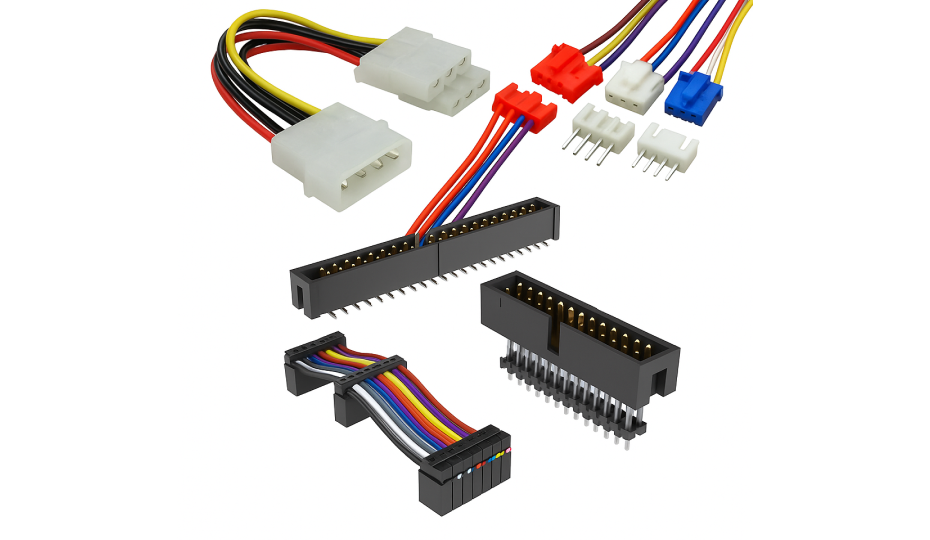
- Molex: Durable and widely used in power supplies and cooling fans. Suitable for higher current loads.
- JST: Compact and reliable connectors found in Li-ion battery packs, small motors, and sensor modules. Popular variants include JST-XH (2.54mm) and JST-PH (2.0mm).
- IDC (Insulation Displacement Connector): Ideal for ribbon cables and flat-wire board-to-board connections. No wire stripping needed.
Typical applications include battery connections, sensor boards, LED strips, and modular circuit assemblies.
Key Factors When Choosing a Electrical Connector
Connector selection involves more than matching pin counts or shapes. The electrical, mechanical, and environmental requirements of your project need to be carefully evaluated.
The following considerations will help ensure your connectors perform reliably over time and under real-world conditions.
1. Electrical Connector Type and Application Context
Start by identifying the connection’s purpose within your system.
Is it delivering power, transferring data, sending signals, or interacting with other modules or devices?
Then choose a connector type that aligns with your product’s physical layout and electrical role.
2. Electrical Ratings: Voltage and Current Handling
A connector’s voltage and current limits must be compatible with your system. Ignoring these ratings can lead to excessive heat, arcing, or component failure.
- Voltage Rating: Indicates the maximum voltage the connector can safely isolate between terminals. Ensure it exceeds your circuit’s expected voltage levels.
- Current Rating: Defines the maximum current per pin. Exceeding this limit can cause overheating or melting of contacts.
For example, a motor drawing 4A at 12V requires a connector rated for at least 4A continuous load, preferably with a safety margin.
3. Pin Count and Pitch
The number of electrical contacts (pins) and their spacing directly affect the compactness or complexity of connections.
- Pin Count: Can range from 2 (for basic power lines) to 40+ (e.g., for ribbon cables or multi-channel I/O).
- Pitch: The center-to-center distance between adjacent pins. Common pitches include:
- 2.54 mm (standard breadboard spacing)
- 1.27 mm (half-pitch)
- 1.0 mm or 0.8 mm (used in compact, high-density designs)
Always confirm that both connector sides (male/female) use compatible pin counts and pitch to prevent misalignment.
4. Connector Gender: Male vs. Female
Most connectors are offered in male (pin) or female (socket) formats. Proper pairing ensures secure mating and system safety.
- Male connectors feature protruding pins.
- Female connectors house recessed contacts.
Male headers should be placed on the PCB, and female connectors should be placed on cables or external modules, especially when contact protection or hot plugging is a concern.
5. Environmental Resistance: IP Ratings and Durability
If your project is exposed to physical stress, humidity, dust, or temperature extremes, environmental protection becomes critical.
- IP Ratings: An IP67 connector, for example, is dust-tight and can survive temporary immersion in water. Choose accordingly based on outdoor or industrial use.
- Temperature Range: Look for rated ranges like –40°C to 85°C, especially for automotive, outdoor, or industrial environments.
- Corrosion Resistance: Gold-plated contacts help prevent oxidation and maintain stable electrical properties over long periods.
6. Mounting Style and Mechanical Orientation
The connector’s mechanical form factor must be compatible with your PCB layout, enclosure design, and mechanical stresses.
- Mounting Orientation: Depending on available space and desired cable routing, choose from straight, right-angle, or vertical connectors.
- Mounting Methods
- Through-Hole: Stronger mechanical bond, ideal for connectors that endure frequent plugging/unplugging.
- Surface-Mount (SMT): Compact and suitable for automated assembly, but mechanically weaker.
- Panel-mount: This type of mount provides external access while anchoring the connector to the enclosure rather than the PCB for connectors like USB or Ethernet ports.
Ensure the connector form and mount style match your product’s casing and assembly requirements.
Case Studies: Real-World Lessons in Connector Selection and Performance
Electrical connectors are not just passive components. They are often at the heart of electronic systems’ performance, safety, and reliability.
The following real-world case studies demonstrate how connector design, materials, and usage choices can make or break system functionality across diverse industries.
Automotive Industry
A major automotive assembly plant reported that over 40% of electrical issues were due to connector misalignment and improper insertion during manual assembly.
Teams redesigned connectors with keyed housings and locking tabs, introduced ergonomic tools for operators, and reinforced documentation.
Human error was reduced, electrical defect rates fell, and throughput on the line improved without increasing assembly time.
Robotics and Automation
Robotic arms in a packaging plant suffered cable and connector failures due to repetitive bending and vibration.
Designers introduced continuous-flex cables rated for high-cycle motion and added strain relief features to all cable-to-connector joints.
Cable life is extended by over 3x, reducing maintenance costs and improving uptime in automated processes.
Data Centers
In high-speed server racks, connectors introduce EMI (electromagnetic interference), causing unstable data transmission.
System integrators adopted shielded IDC connectors, implemented twisted-pair layouts, and added ferrite beads near connector interfaces.
Signal integrity improved measurably, and data errors in high-bandwidth environments were virtually eliminated.
Oil & Gas Sector
In downhole drilling operations, connectors failed due to broken ceramic and glass insulators exposed to extreme heat, pressure, and corrosive chemicals.
Engineers switched to advanced thermoplastics like PEEK (Polyether ether ketone) and PEI (Polyetherimide), which offer superior thermal and chemical resistance.
There was a significant increase in connector reliability, which reduced downtime and prevented expensive equipment replacements.
Common Connector Problems and How to Solve Them
Proper connector selection, handling, or environmental exposure can cause a wide range of issues, from minor communication glitches to complete system outages.
Below are the most common connector-related problems and practical ways to resolve them.
Loose or Intermittent Connections
Frequent mating cycles, misalignment, or poor soldering can cause unstable connections, leading to signal loss.
Use locking connectors like JST or Molex, and consider through-hole mounting in vibration-prone areas. Re-crimp or reflow faulty joints and replace connectors past their rated mating cycles.
Corrosion and Oxidation
Moisture and air exposure can oxidize contacts, especially tin-plated ones, increasing resistance.
For better longevity, use gold-plated connectors, apply dielectric grease, and opt for sealed or IP-rated connectors like M8/M12 for outdoor or humid environments.
Choose sealed IP66-rated connectors like HEAVYCON feedthroughs to avoid corrosion and moisture ingress in outdoor applications.
Mismatched Connector Types
Incorrect pitch, gender, or connector series can lead to poor fits or system failure. Always verify part numbers and datasheets.
So try to use keyed or polarized connectors to avoid errors, and standardize connector types across your designs.
Overheating or Arcing
Underrated connectors can overheat or arc under high current.
Also, choose connectors with a safety margin above expected loads, like XT60 or Powerpole, and ensure proper spacing and airflow around high-current paths.
Physical Damage or Misuse
Misalignment, rough handling, or pulling on wires can damage connectors. Use alignment guides, shrouded headers, and cable strain relief.
Therefore, educate users to disconnect via housings, not cables, especially in high-use areas.
Signal Interference and Noise
Unshielded or improperly grounded connectors can introduce EMI, affecting data integrity. Use shielded connectors, twisted-pair cables, and consistent grounding.
Filtered connectors or ferrite beads can improve stability in noisy environments.
Final Thoughts
Whether building a simple sensor module or a rugged industrial system, choosing the right connector can make or break your design.
Connectors are fundamental to system integrity, scalability, and performance, from ensuring reliable power delivery to supporting high-speed data transfer.
Furthermore, understanding connector types, standards, and common failure points helps engineers and makers design smarter, more resilient electronics.
If you’re looking for high-quality, affordable electrical connectors to support your next project, explore FlyWing Technology’s connector catalog. With their large selection and technical specs, you can find exactly what your design demands.
Frequently Asked Questions (FAQ)
-
What is the difference between board-to-board and wire-to-board connectors?
Board-to-board connectors directly link two PCBs without wires, ideal for compact layouts and modular designs. Wire-to-board connectors attach external wires to a PCB which is perfect for power inputs, sensors, or peripheral modules.
-
How do I know which connector to use for my project?
Start by identifying your connection’s purpose—power, signal, data, or mechanical interface. Then check the required voltage/current ratings, environmental conditions, pin count, and mounting style.
-
What do connector pitch and pin count mean?
Pitch is the distance between adjacent pins (e.g., 2.54 mm is standard for breadboards). Pin count refers to how many electrical paths a connector supports. Choose based on how many signals or power lines you need to route.
-
Why do connectors fail over time?
Common issues include loose mating, corrosion, mismatched types, or overcurrent. Frequent plugging and unplugging can also wear out contacts.
-
Are gold-plated connectors better than tin-plated ones?
Yes, especially for long-term use or humid environments. Gold resists oxidation and maintains low resistance over time, making it ideal for signal integrity and reliability.
-
Can I use the same USB connector for power and data?
Yes. USB connectors like Type-A, Micro-USB, or USB-C support both power delivery and data transfer. You need to make sure your component supports dual functionality and the cable is rated for both.
-
What is an IP67-rated connector?
It’s a connector that’s fully dust-tight (6) and protected against temporary water immersion (7). Perfect for outdoor, marine, or rugged environments. FlyWing offers IP-rated circular and terminal block connectors for such needs.
-
What happens if I mismatch connectors (e.g., JST-XH with JST-PH)?
They may appear similar but have different pin pitches and mechanical keys, which can lead to poor contact or damage. Always verify datasheets and use exact matching types.
-
How important is shielding in connectors?
Very important in high-speed or noise-sensitive circuits. Shielded connectors reduce EMI (electromagnetic interference), improving signal quality in data lines or analog sensors.
-
Where can I buy high-quality connectors for prototyping or production?
You can explore FlyWing Technology’s Connector Catalog for a wide range of board-to-board, wire-to-board, terminal blocks, circular connectors, and more. Their components are suitable for industrial, consumer, and embedded applications—with clear specs and global shipping.