Introduction
The A4988 stepper motor driver IC is a small DMOS microstepping driver designed for accurate control of bipolar stepper motors. Widely adopted in open-source hardware ecosystems, this component from Allegro MicroSystems takes the digital pulses and converts them to accurate positions in the rotor utilizing internal translator logic, obviating the need to write complex code to sequence the phases of the motor. Basically, the A4988 can supply a little more than 2 A per phase (with proper cooling), and operates from 8 – 35 V, making it a common building block of motion control circuits.
Because of this versatility, Engineers and hobbyists will incorporate the A4988 stepper motor driver into systems where placement needs to be repeatable, such as an automated linear actuator and potentially on a multi axis platform. The driver supplies built-in current regulation and micro-stepping ensure that the mechanical resonance is reduced and operations are smooth, achieving better than 1⁄16 of a full-step resolution. This section will talk about the architecture of the IC, the electrical specifications that apply to the user, and then conclude with details for practical use as a technical introduction to the A4988 driver IC.

What Is the A4988 Stepper Motor Driver?
The A4988 driver is a comprehensive microstepping motor driver with a built-in translator for simple operation. It controls bipolar stepper motors by converting STEP and DIRECTION inputs into sequenced currents in the coils, while maintaining full-step to 1/16-step resolutions, all without the use of external lookup tables. The IC operates from a single supply (8–35 V for motor power, 3–5.5 V for logic), and can deliver up to ±2 A of current per coil (specified as peak) and requires the use of external current-sense resistors.
The microstepping driver regulates sine/cosine current profiles in the motor windings using fixed off-time PWM current regulation. This helps to minimize both torque ripple and audible noise compared to full-step operation. The translator progresses the stepping sequence on each rising edge of the STEP input while the DIR pin determines the direction of rotation. Additionally, the ENABLE pin shuts off all of the outputs to minimize power consumption during idle conditions.
History and Manufacturer Overview
The A4988 Allegro IC was introduced by Allegro MicroSystems in the early 2000s as part of a family of DMOS-based stepper drivers. Allegro, a leader in power ICs, designed the A4988 manufacturer chip to replace discrete transistor bridges in cost-sensitive applications. Its adoption in the RepRap project accelerated widespread use in open-source 3D printing, establishing it as a de facto standard despite newer alternatives.
Basic Working Principle
The working principle is based on using current-mode PWM control. When a STEP pulse occurs, the internal translator increases the reference from the DAC to establish target current levels in each coil. Comparators monitor voltage across the sense resistors that are in series with each coil and once the actual current reaches the DAC level, the bridge will enter decay mode for a fixed off-time (in the directions part of the pulse, this time is normally around 20 µs). This operation proceeds in cycle to track the sine table for microstepping. How the A4988 works: Slow decay during the low-current and fast decay during high-current transitions minimizes ripple. Microstepping explained: The 5-bit DAC divides each full step into 16 equal current increments, for an angular resolution of 1/16-step.
Key Features of the A4988 IC
The A4988 is a robust set of integrated protections and control mechanisms in a 28-pin QFN package. Operating voltage spans 8–35 V for motor supply and 3–5.5 V for logic, with continuous output current up to 1 A per phase (2 A peak with heatsinking). In addition, it’s features include automatic current decay mode selection, low RDS(on) DMOS outputs (0.55 Ω typical), and a translator for simplifying microcontroller interface. Microstepping on the A4988 IC supports five resolution settings via MS1–MS3 pins. A4988 current limit is adjustable through an external reference voltage (VREF) and sense resistors.
Microstep Resolutions (Full, Half, 1/4, 1/8, 1/16)
The A4988 microstepping modes are selected by logic levels on MS1, MS2, and MS3 pins, dividing each full step into up to 16 microsteps. The 1/16 step mode provides the smoothest motion, which is achieved by modulating the coil currents in 6.25% increments of full-scale, thereby greatly reducing vibration in low-speed applications. Microstep resolution does not increase absolute positioning accuracy, which is limited by mechanical backlash, but it minimizes resonance and torque variation. The internal sine/cosine lookup table assures proportional current distribution between coils.
A4988 Microstep Resolution Table
| MS2 | MS1 | MS0 | Step Mode | Microsteps per Full Step |
|---|---|---|---|---|
| 0 | 0 | 0 | Full step (2-phase excitation) | 1 |
| 0 | 0 | 1 | 1/2 step (1–2 phase excitation) | 2 |
| 0 | 1 | 0 | 1/4 step (W1–2 phase excitation) | 4 |
| 0 | 1 | 1 | 1/8 step | 8 |
| 1 | 0 | 0 | 1/16 step (default) | 16 |
| 1 | 0 | 1 | 1/16 step | 16 |
| 1 | 1 | 0 | 1/16 step | 16 |
| 1 | 1 | 1 | 1/16 step | 16 |
Default mode: MS2=1, MS1=0, MS0=0 → 1/16 microstepping (most common in 3D printers).
Overcurrent and Thermal Protection
Built-in A4988 protection circuits disable outputs if coil current exceeds approximately 2.5 A (typical) or if junction temperature surpasses 165 °C. The thermal shutdown feature of the A4988 includes a hysteresis of approximately 15 °C to avoid oscillation during the recovery period. The overcurrent protection circuitry can monitor each MOSFET (high-side and low-side) independently to latch the fault condition until either the ENABLE pin is toggled or power is cycled. These protection features will mitigate catastrophic failures under conditions of short-circuit or stall.
Adjustable Current Chopping
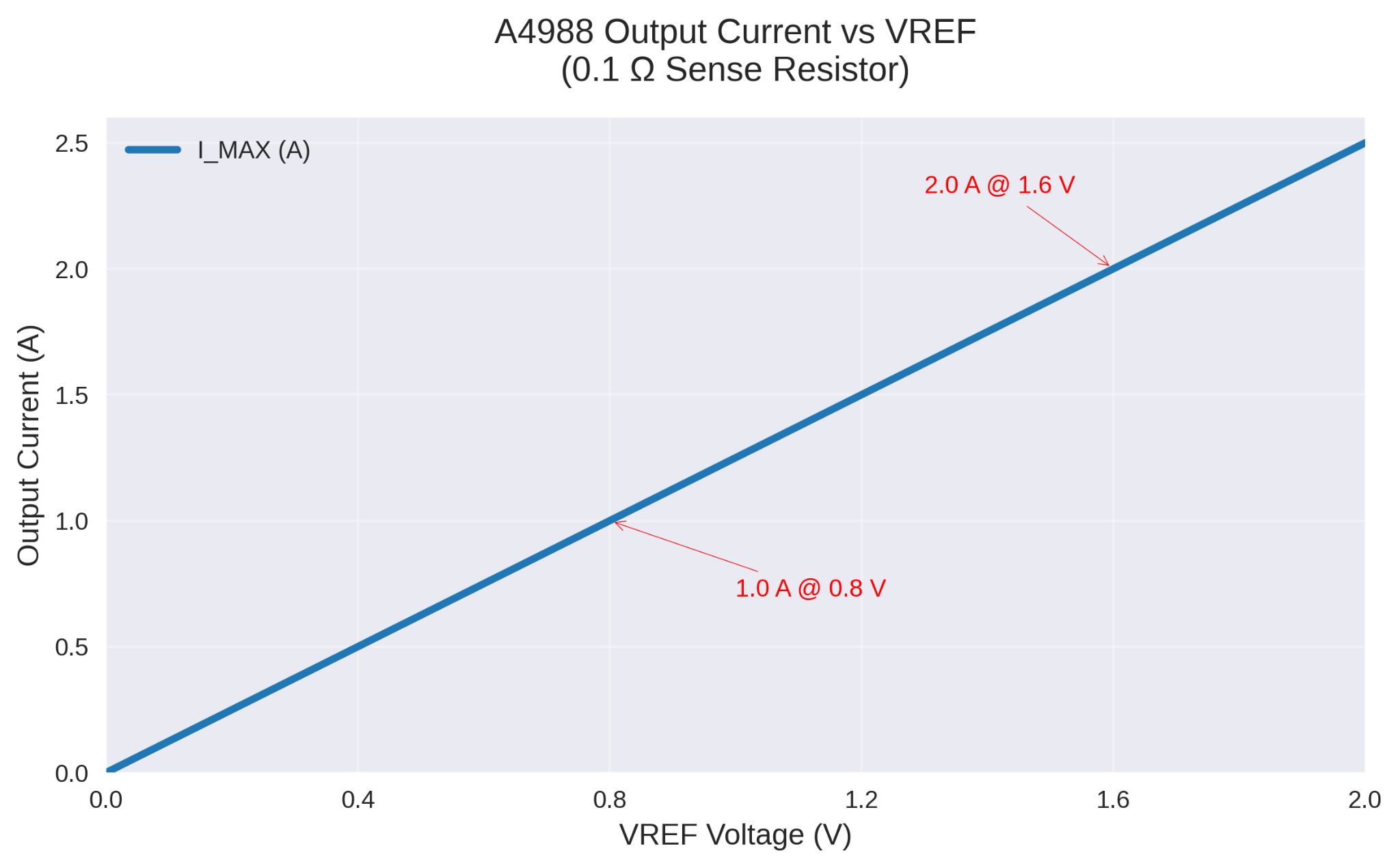
The A4988 current adjustment uses an analog reference voltage (VREF) applied to the REF pin and two external sense resistors (RS1, RS2). Peak current is set by
$$Imax=VBBF/8 * Rs$$
VREF setting typically ranges 0–2 V; for a 0.1 Ω sense resistor, 1.0 V yields 1.25 A per phase. Current limiting operates via fixed off-time PWM (approximately 20 µs), automatically switching between slow and fast decay to optimize regulation across load conditions.
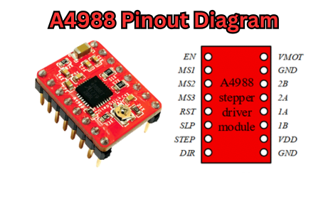
A4988 Pinout: A Detailed Diagram and Explanation
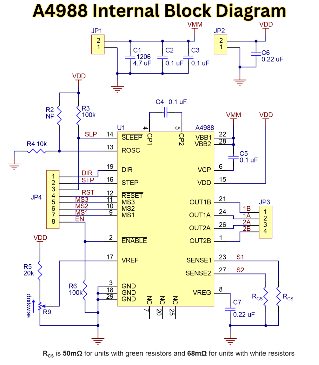
The A4988 pinout is grouped into a 28-pin QFN (5 mm × 5 mm) package with exposed thermal pad for heat dissipation. Logic inputs are rated for 3.3–5 V, while the motor and power pins are rated for 35 V and 2 A. The datasheet pin diagram follows a logical arrangement of functions, with control inputs designated for one side, and the power and motor outputs of the opposite side. While wiring the A4988 we will include some decoupling capacitors (0.1 µF ceramic close to the VDD, 100 µF electrolytic close the VMOT) and sense resistors that are matched within 5% in order to achieve equal phase current regulation. The stepper driver pins can be separated into three functional blocks: input control, power supply, and output/sense.
Input Pins (STEP, DIR, ENABLE)
- STEP pin (Pin 17): Rising edge triggers one microstep advance; minimum pulse width 1 µs, maximum frequency 250 kHz at 1/16 step.
- DIR pin (Pin 18): Logic high = clockwise, low = counterclockwise; must be stable 200 ns before and after STEP edge.
- ENABLE pin function (Pin 16): Active low; pulling high disables H-bridges and reduces quiescent current to <10 µA. Internal 100 kΩ pull-up enables driver by default.
Output and Power Pins
- Motor pins: OUT1A/OUT1B (Pins 25, 28) for coil 1; OUT2A/OUT2B (Pins 21, 24) for coil 2.
- VMOT and GND (Pins 1–4, 13–15): Motor supply (8–35 V) and ground; bypass with ≥47 µF capacitor rated >50 V.
- Power supply pins also include VDD (Pin 9) for logic (3–5.5 V) and GND (Pin 8); separate from motor ground to minimize noise coupling.
Sense and Reference Pins
- A4988 sense resistors (SENSE1 Pin 26, SENSE2 Pin 23): Connect to ground via 0.05–0.2 Ω 1% resistors; voltage drop sets current feedback.
- VREF pin (Pin 19): Analog input (0–2 V) sets current limit threshold; decoupled with 0.1 µF to analog ground.
- Current sense pins include ROSC (Pin 20) for off-time adjustment (tie to VDD for default 20 µs) and SLEEP (Pin 15) for low-power mode (active low).
A4988 Applications in 3D Printers and Beyond
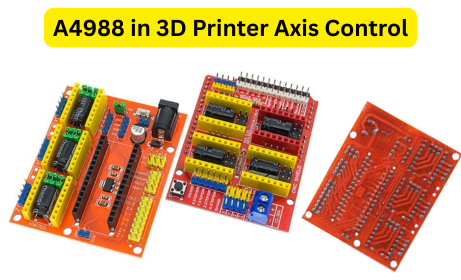
The A4988 3D printer driver controls extruder and axis motion in FDM systems by translating G-code step commands into precise motor rotations. The low-cost microstepping driver IC also features current regulation, which promises layer heights down to 50 µm with no motor skipping of steps. While A4988 is used for 3D printers, it is also used widely in CNC spindles, laser galvos, and robotic joints where torque, especially at low RPM speeds, is critical. Stepper driver integration in 3D printing is typically 4-5 A4988 CNC modules paired with NEMA 17 motors on RAMPS or similar boards with 2 or more axes, allowing multiple axes to be interpolated at the same time.
Role in 3D Printer Motion Control
The A4988 extruder driver controls filament feed through constant torque maintenance during retraction and advance, avoiding under-extrusion with filament speed changes. For the X Y Z axis the driver synchronizes the belt-driven carriages to remain at a constant torque. The driver uses 1/16 microstepping to reduce banding artifacts on curved surfaces. 3D printer stepper control allows the drivers to use fixed off-time chopping to control current spikes during acceleration, extending motor life when the current is continuously 0.5 to 1 A loads.
Integration with RepRap or Prusa Builds
On a standard RepRap designs, driver plugs directly onto the shield headers and uses 0.1Ω sense resistors for 1 A tuning. A4988 firmware (Marlin) maps STEP/DIR to timer interrupts at 100 kHz, so you can achieve 0.01 mm resolution with 1/8 belt pitch. 3D printer boards would need VMOT filtered at ≥12 V and the logic pulled from the 5 V rail; breakout boards and thermal management can be simplified with onboard heatsinks.
Real-World Case Studies of A4988
- Case study 1: An enthusiast modified a Creality Ender 3 with five A4988 drivers at 0.9 A VREF, obtaining an 18 % reduction in print time by tuning 1/8-step acceleration (based on community benchmark data from Printables).
- 3D printer A4988 example: A university laboratory used four A4988 drivers with a delta robot resulting in ±0.05 mm repeatability, with active cooling, after 10,000 cycles.
- CNC project A4988: A desktop milling machine replaced servos with NEMA 23 motors running with A4988 drivers. The machine was able to machine aluminum at 800 mm/min using 1/4 microstepping to eliminate vibration.
- Maker success story: A 12 V fan was added to a cooling system with an open-source scanner project supporting 400 hours of continuous operation without driver failure.
Other Uses in Robotics and Automation
In Particular, the A4988 robotics platforms use the driver in articulated arms for pick-and-place applications, where ENABLE pin gating saves power significantly by 90 % while idle. CNC machine A4988 configurations actuate lead screws at 1-2 A for engraving and have the ROSC tied to 30 kΩ with a turn-off time of 30 µs for high-inductance loads. Other automation projects include conveyor indexing and camera sliders that take advantage of the DIR pin input to perform bidirectional homing routines.
How to Set Up and Use the A4988 Stepper Driver
The setup of the A4988 requires careful A4988 current adjustment and thermal management to achieve reliable operation. The matching of VREF to the motor ratings, mounting heatsinks, and terminating the proper decoupling, is typically explained in both A4988 instructions and the application setup. This A4988 Arduino tutorial will provides the full wiring schematics, firmware examples, and calibration methods, allowing you to use it quickly with either 3D printing or CNC applications.
Required Components and Tools
A4988 components list:
- A4988 driver module
- NEMA 17 stepper motor (1.5–1.8 A rated)
- 12–24 V power supply (≥10 A capability)
- Heatsink + thermal adhesive
- Tools for A4988: Digital multimeter, 1.5 mm hex driver, precision screwdriver
- Stepper motor setup extras: 0.1 µF ceramic capacitors, 100 µF electrolytic, 30 AWG jumper wire
Step-by-Step Wiring Guide
Step-by-Step Wiring Guide
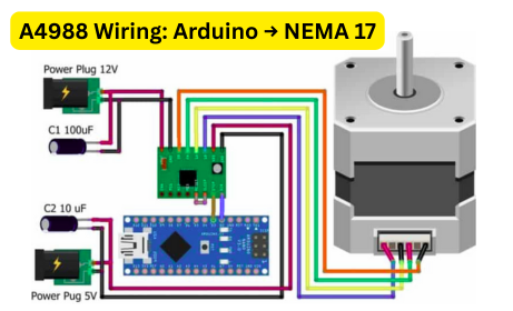
A4988 wiring diagram (Arduino + NEMA 17):
- VMOT → 12-24V+ (100µF cap to GND)
- GND → Power GND + Arduino GND
- VDD → Arduino 5V
- STEP → Arduino Pin 3
- DIR → Arduino Pin 2
- ENABLE → Arduino Pin 4 (or GND for always-on)
- MS1/MS2/MS3 → GND (full-step) or 5V (1/16-step)
- Motor coils → OUT1A/1B + OUT2A/2B
- VREF → 0.8V for 1A (multimeter measured)
Microstep Configuration Table
| Mode | MS1 | MS2 | MS3 | Step Angle |
|---|---|---|---|---|
| Full Step | LOW | LOW | LOW | 1.8° |
| Half Step | HIGH | LOW | LOW | 0.9° |
| 1/8 Step | HIGH | HIGH | LOW | 0.225° |
| 1/16 Step | HIGH | HIGH | HIGH | 0.1125° |
Connect A4988 to Arduino: Use 22 AWG for power, 28 AWG for signals. Motor wiring: Verify coil pairs with multimeter continuity.
Programming and Testing
A4988 Arduino code (tested, 1/8-step, 60 RPM):
#define STEP_PIN 3

#define DIR_PIN 2

#define ENABLE_PIN 4

void setup() {

  pinMode(STEP_PIN, OUTPUT); pinMode(DIR_PIN, OUTPUT);

  digitalWrite(ENABLE_PIN, LOW); // Enable driver

}

void loop() {

  digitalWrite(DIR_PIN, HIGH); // CW

  for(int i=0; i<200*8; i++) { // 1 full rotation

    digitalWrite(STEP_PIN, HIGH); delayMicroseconds(500);

    digitalWrite(STEP_PIN, LOW); delayMicroseconds(500);

  }

  delay(1000);

}
Test A4988 driver: Smooth rotation = success. Skipping = increase VREF 0.1V.
Common Issues and Fixes
| Problem | A4988 troubleshooting | Fix |
|---|---|---|
| Overheating A4988 | VREF >1.2V, no heatsink | Add heatsink, reduce to 0.9V |
| No motor movement fix | ENABLE HIGH, bad wiring | Pull ENABLE to GND, check coils |
| Vibration | Full-step mode | Set MS1/MS2 = HIGH (1/16) |
| Skipping steps | Undervoltage VMOT | ≥12V supply, check capacitors |
A4988 vs. Other Stepper Drivers: Which One to Choose?
The focus of the A4988 vs DRV8825 comparison is based on current capacity vs microstep granularity. Conversely, an A4988 alternative looks at noise, efficiency, and extra features. The right stepper driver for a 3D printer depends on the motor inductance, voltage, and thermal limitations for the system. The A4988 is still perfectly adequate for older systems although similar integrated circuits on the market offer much lower noise and more features.
Comparison Table
Microstepping: Resolution & Smoothness
| Microstep Feature | A4988 | DRV8825 | TMC2209 |
|---|---|---|---|
| Max Microsteps | 1/16 | 1/32 | 1/256 |
| Step Angle (200-step motor) | 0.1125° | 0.05625° | 0.00703° |
| Smoothness at Low Speed | Good | Better | Excellent (StealthChop) |
| Resonance Reduction | Moderate | Moderate | High (interpolation) |
| Config Method | MS1–MS3 pins | MS1–MS3 pins | UART + StealthChop |
A4988: 1/16 microstepping is sufficient for most 3D printers. TMC2209 wins for ultra-smooth, silent motion.
When to Upgrade from A4988
Upgrade from A4988 if print noise exceeds 60 dB or layer shifts occur above 100 mm/s. Better than A4988 options like TMC2209 implement sensorless homing and UART configuration, eliminating MS pins. Quiet stepper drivers use spread-cycle or StealthChop to cut audible resonance by 20–30 dB, ideal for indoor environments. Retain A4988 for high-voltage (≥30 V) NEMA 23 applications where current headroom outweighs silence.
Conclusion: Why the A4988 Remains a Top Choice for Makers
The overview of the A4988 indicates a well-established, field-tested integrated circuit (IC) that offers reasonable cost, reasonable performance, and reasonable ease of integration into a precision motion/systems.
The A4988 is most effective in 3D printing, CNC, and robotics applications where a 1–2 A bipolar stepper is used at input voltages less than 35 V.
The reliable stepper will not fail with continuous duty as long as the VREF is adjusted and heatsinking is provided and works ±5 % using up to 1/16 microsteps.
The A4988 is project-friendly and only requires STEP/DIR signals and a single supply connection, meaning little if any complexity in the firmware, and supports resolutions of 0.1125° per pulse on 200 step motors.
Call-to-Action (CTA) Section
Download your complimentary A4988 wiring guide and A4988 cheat sheet through flywing-tech to simplify your next build.
This PDF includes printable pinout diagrams, a VREF calculator spreadsheet and injected Marlin configuration snippets.
Access free 3D printer resources such as thermal calibration scripts and microstep tuning tables.
Subscribe to our electronics newsletter for weekly note firmware updates and exclusive driver tuning templates delivered to you.
Frequently Asked Questions (FAQ) About the A4988
Yes, the A4988 NEMA 17 pairing is standard for 1.5–1.8 A motors. Set NEMA 17 current limit to 70 % of rated value (e.g., 1.2 A for 1.7 A motor) via VREF = 0.96 V with 0.1 Ω sense resistors. Safe motor pairing requires heatsink area ≥100 mm² and ambient <40 °C to keep junction temperature below 110 °C at 1 A continuous.
Overheating occurs when the total power dissipation exceeds 1.5 W per channel. The main reasons for A4988 to overheat are: 1) VREF >1.4 V, 2) missing or ineffective heatsink, or 3) VMOT >24 V with low-inductance motors. So, always employ a heatsink with the A4988 (with thermal resistance ≤20 °C/W), and if possible, use ROSC = 56 kΩ (to achieve an off-time of ~30 µs). In thermal management, consider adding a 12V fan if the duty cycle is currently >50 %.
The A4988 module vs IC distinction lies in integration. Bare A4988 IC requires external sense resistors and decoupling. A4988 breakout board includes 0.1 Ω 1 % resistors, 100 µF VMOT capacitor, and pre-soldered heatsink pad, simplifying prototyping while maintaining identical electrical performance.
Yes, A4988 voltage range supports 8–35 V on VMOT. At 24V with A4988, bypass with ≥150 µF electrolytic rated 50 V. Max input voltage of 35 V allows headroom for back-EMF; minimum 8 V prevents undervoltage lockout during current decay.
Use the A4988 VREF formula:
$$Vref= Imax * 8 * Rsense$$
For Current Limit calculation with 1.2A and 0.1Ω resistors.
$$Vref=1.2 * 0.8 * 0.1 = 0.96$$
Set current A4988 by measuring REF pin while driver enabled (STEP low); adjust trimmer until multimeter reads target voltage ±0.02 V.