If you’re building a DIY car diagnostics tool, a robotic arm, or an industrial sensor network, CAN bus (Controller Area Network) is the gold standard for real-time communication between devices. But what if your microcontroller doesn’t have native CAN support? That’s where the MCP2515 CAN bus module comes in.
The MCP2515 is a stand-alone CAN controller that makes it easy to add CAN functionality to platforms like the Arduino Uno, ESP32, Raspberry Pi, and more. With just a few wires and an SPI connection, you can join or build a full CAN network.
In this article, we’ll take a deep dive into the MCP2515:
- What it does and how it works
- How to wire it up and get started with Arduino
- Where it performs well and where it doesn’t
- And a practical comparison with the STM32F103C8T6, a popular microcontroller with native CAN support
Let’s get started.
Introduction to CAN Bus
The Controller Area Network (CAN bus) is a robust, real-time communication protocol originally built for automotive systems and now widely used in industrial automation, robotics, medical devices, and other environments where reliability is non-negotiable.
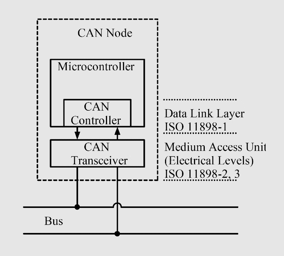
It allows multiple electronic control units (ECUs) and sensors to exchange data over a simple two-wire differential bus while providing:
- Multi-master communication (any node can speak when the bus is free)
- Priority-based arbitration (critical messages always win)
- Strong noise immunity
- Automatic error detection and retransmission
These features make CAN ideal for distributed systems that need deterministic timing and fault-tolerant communication.
Many modern microcontrollers include built-in CAN support, but a large number of popular development boards like the Arduino Uno, basic ESP8266 boards, and most 8-bit MCUs do not.
This creates a gap for hobbyists, students, and engineers who want to experiment with CAN without switching to a new microcontroller platform. That’s where external controllers come in.
One of the most widely adopted solutions for adding CAN support to non-CAN microcontrollers is the MCP2515, a small SPI-based controller that lets almost any MCU join a CAN bus with minimal hardware.
MCP2515 Overview
The MCP2515 is a stand-alone CAN controller from Microchip designed to add CAN bus support to microcontrollers that don’t have a built-in CAN peripheral.
It fully supports the CAN 2.0A/B standard and connects to the host MCU through SPI, making integration straightforward.
Internally, the MCP2515 handles arbitration, error checking, message filtering, and buffering. This offloads the low-level CAN protocol work from the main microcontroller.
Key features include:
- 3 transmit buffers
- 2 receive buffers with masks
- 6 acceptance filters
- SPI up to 10 MHz
- CAN bus speeds up to 1 Mbps
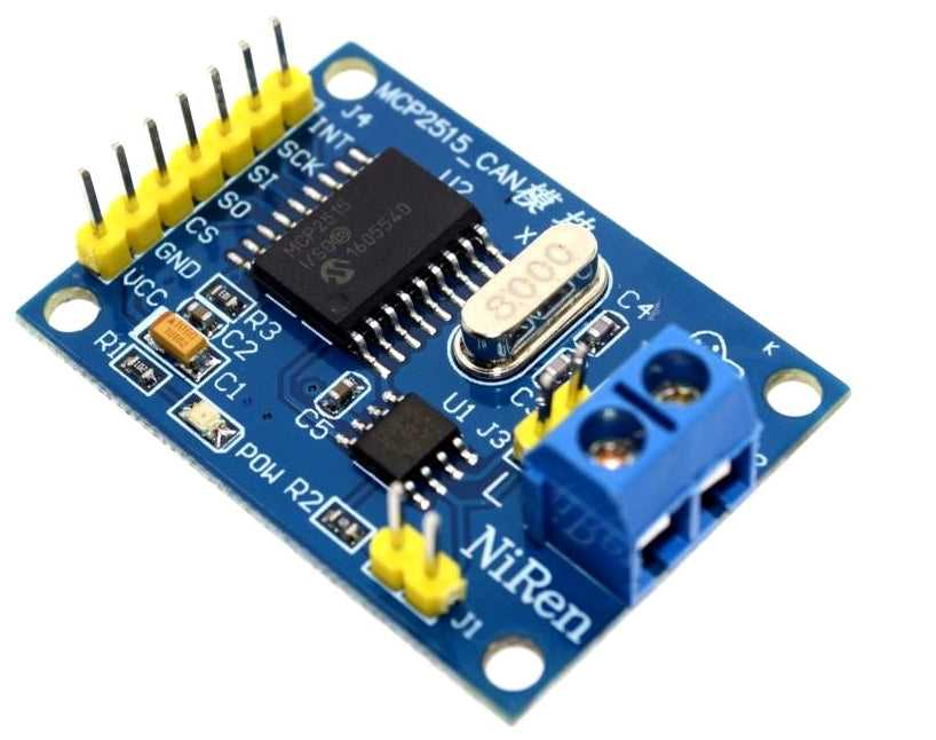
Most MCP2515 modules use an 8 MHz crystal and come paired with a high-speed CAN transceiver such as the TJA1050 or MCP2551.
They also include CANH/CANL terminals, SPI pins, and a jumper-selectable 120 Ω termination resistor.
In operation, the MCU exchanges CAN frames with the MCP2515 over SPI, while the controller manages bus arbitration, timing, and interrupts.
This makes it a practical way to add CAN functionality to boards like the Arduino Uno.
Despite the availability of microcontrollers with built-in CAN, the MCP2515 remains widely used due to its low cost, reliable performance, and strong Arduino library support.
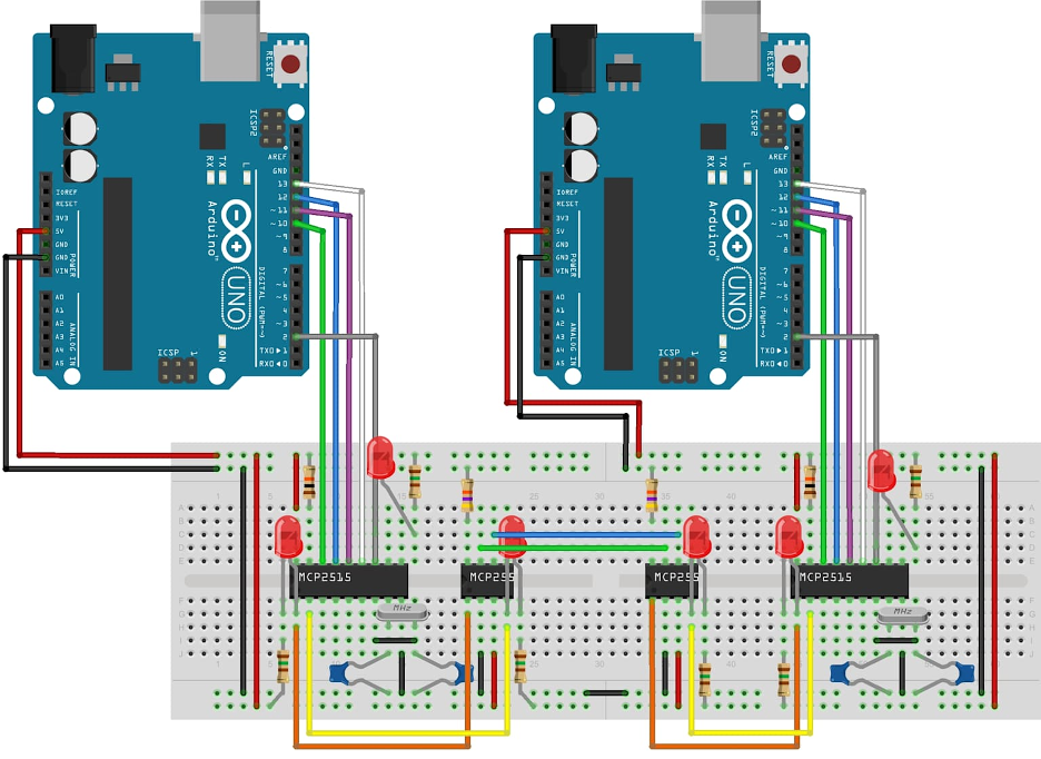
MCP2515 Wiring & Arduino Setup
In this setup, each CAN node uses an ATmega328P Arduino (Uno/Nano) together with an MCP2515 CAN module, which bundles the MCP2515 controller and a transceiver such as the TJA1050 or MCP2551.
Below is the typical connection for an Arduino Uno (ATmega328P):
- VCC → 5V supply
- GND → Arduino ground
- CS (Chip Select) → D10
- MOSI (SI) → D11
- MISO (SO) → D12
- SCK → D13
- INT → D2 (external interrupt pin)
- CANH / CANL → CAN bus high and low wires
Some modules also break out optional pins like RST, RX0BF/RX1BF, or TXnRTS, but these are not required for basic operation.
To form a CAN network, you need at least two nodes, each with its own MCP2515 + transceiver + MCU. Connect CANH to CANH and CANL to CANL, and make sure all nodes share a common ground.
For short breadboard setups, simple jumper wires work, but for longer distances or noisy environments, use twisted-pair wiring for CANH/CANL.
The CAN bus must be properly terminated with 120 Ω resistors at both physical ends. MCP2515 modules usually include an onboard terminator that can be enabled or disabled using a jumper.
If you have exactly two nodes, enable termination on both modules; with more nodes, ensure only the two at the ends are terminated.
Arduino Library Setup
Several Arduino libraries make working with the MCP2515 easy. Popular options include:
- “mcp_can” library
- “arduino-mcp2515” library
- ACAN2515 library (high performance)
Install a library via the Arduino Library Manager, include it in your sketch, and initialize CAN with something like:
CAN.begin(CAN_500KBPS, MCP_8MHZ);
The library handles bit timing and register configuration internally.
Sending and Receiving CAN Frames
With two MCP2515 nodes wired and initialized, one Arduino can transmit and the other can receive. For example, using the “mcp_can” library:
Send:
CAN.sendMsgBuf(0x100, 0, 8, data_array);
Receive:
CAN.readMsgBuf(&id, &len, buf);
This basic loop is often used to send simple data—like a sensor reading—from one Arduino and display it on the other. If both nodes receive and decode messages correctly, your CAN network is operating as expected.
Quick Setup Checklist
- Connect SPI pins: D10 → CS, D11 → MOSI, D12 → MISO, D13 → SCK, D2 → INT
- Tie CANH to CANH, CANL to CANL, and share ground
- Enable termination resistors at both ends of the bus
- Install and configure an MCP2515 library
- Load example send/receive sketches and match the baud rate and crystal frequency
- Use the Serial Monitor to confirm communication between nodes
Once communication is working, you can expand the network to control motors, read vehicle CAN data, or link multiple microcontrollers in a larger CAN system.
Performance Characteristics of MCP2515
The MCP2515 is best understood when working from a performance standpoint. However, its external SPI-based design introduces some limitations compared with microcontrollers with built-in CAN peripherals.
The following points break down its behavior in real applications.
Supported CAN Speeds
The MCP2515 supports all standard CAN 2.0A/B bit rates, from a few kbps up to 1 Mbps. Common speeds include 125 kbps, 250 kbps, 500 kbps, and 1 Mbps. Lower rates (10–50 kbps) are used for longer cable runs. Typical bus lengths range from ~40 m at 1 Mbps to ~1000 m at 50 kbps. Bit timing depends on the module’s oscillator—usually 8 MHz—and must match the configuration used in software.
Latency and Throughput
Because the MCP2515 communicates over SPI, some extra latency is introduced. At 10 MHz SPI, frame transfers are fast, but not zero-delay.
The more significant limitation is the two-deep receive buffer. If frames arrive consecutively and the MCU doesn’t read them immediately, additional frames are dropped.
Under high bus load (~70%+), this limited buffering and SPI overhead can cause missed frames. Native CAN controllers, with larger FIFOs or DMA access, handle burst traffic more reliably.
Message Filtering and Masks
The MCP2515 provides six acceptance filters and two masks for hardware-level message filtering.
This allows the controller to pass only relevant frames to the MCU, reducing interrupt load and improving efficiency on busy buses.
Many example sketches default to “accept all,” but proper filtering is recommended on networks with multiple active nodes.
Oscillator Requirements
The MCP2515 depends on an external crystal oscillator, usually 8 MHz (older modules may use 16 MHz). Software must be configured with the correct crystal frequency; otherwise, bit timing is incorrect and the CAN bus will not function.
Clock stability also affects CAN reliability, especially in thermally variable environments.
Error Handling and Bus Behavior
The MCP2515 implements all standard CAN error-handling features, including CRC checks, ACK errors, stuff-bit detection, retransmissions, and Bus-Off behavior.Note that buffer overflows caused by delayed SPI reads are not flagged as CAN errors and must be handled by the application if needed.
Case Study: MCP2515 CAN Bus Module vs STM32F103C8T6 (Blue Pill)

Scenario: Small Robotics CAN Network
- 1 main controller
- 4 motor nodes (one per joint)
- Each motor node: position/current feedback at 100 Hz
- Main controller: command updates at 100 Hz
- Bus speed: 500 kbps
- Cable length: a few meters inside the robot
You’re building a 4-axis robotic arm: Two realistic architectures are:
- Arduino Uno + MCP2515 CAN bus module at each node
- STM32F103C8T6 “Blue Pill” with built-in CAN at each node (plus a CAN transceiver)
We’ll compare hardware complexity, latency, behaviour under load, and long-term scalability.
Option 1: Arduino + MCP2515 CAN Bus Module
In this setup, each CAN node uses an ATmega328P Arduino (Uno/Nano) together with an MCP2515 CAN module, which bundles the MCP2515 controller and a transceiver such as the TJA1050 or MCP2551.
The MCP2515 communicates with the Arduino over SPI and provides a few core features:
- 3 transmit buffers
- 2 receive buffers
- 2 masks and 6 acceptance filters for selecting which messages trigger interrupt

Every CAN frame must pass through SPI:
- RX path: MCP2515 → SPI → ArduinoTX path: Arduino → SPI → MCP2515
SPI at 10 MHz is fast, but not free—you still pay for SPI transaction time, interrupt latency, and whatever work the Arduino does inside the ISR. Because the MCP2515 only has two RX buffers, back-to-back frames can overflow if the Arduino doesn’t read them quickly enough. When that happens, extra frames are silently dropped (not a CAN-level error).
For the robotic arm example running at 500 kbps with ~100 Hz updates, this setup works well if:
- Bus load stays under ~30–40%
- Interrupts are handled promptly
- Hardware filters are used so only relevant messages trigger interrupts
As the system scales—more nodes, larger messages, or added debug traffic—the combination of SPI overhead and limited buffering can become a bottleneck.
Option 2: STM32F103C8T6 (Blue Pill) with Built-In CAN
In the Blue Pill setup, each node uses an STM32F103C8T6 along with a CAN transceiver (TJA1050 or SN65HVD230) directly to the MCU’s CAN_TX and CAN_RX pins.
Unlike the Arduino + MCP2515 approach, the STM32 has a built-in bxCAN controller, meaning the microcontroller itself handles CAN 2.0A/B at up to 1 Mbit/s without needing an external CAN controller.The bxCAN peripheral provides:
- 3 transmit mailboxes2 receive FIFOs (3 frames deep each)~14 hardware filter banks
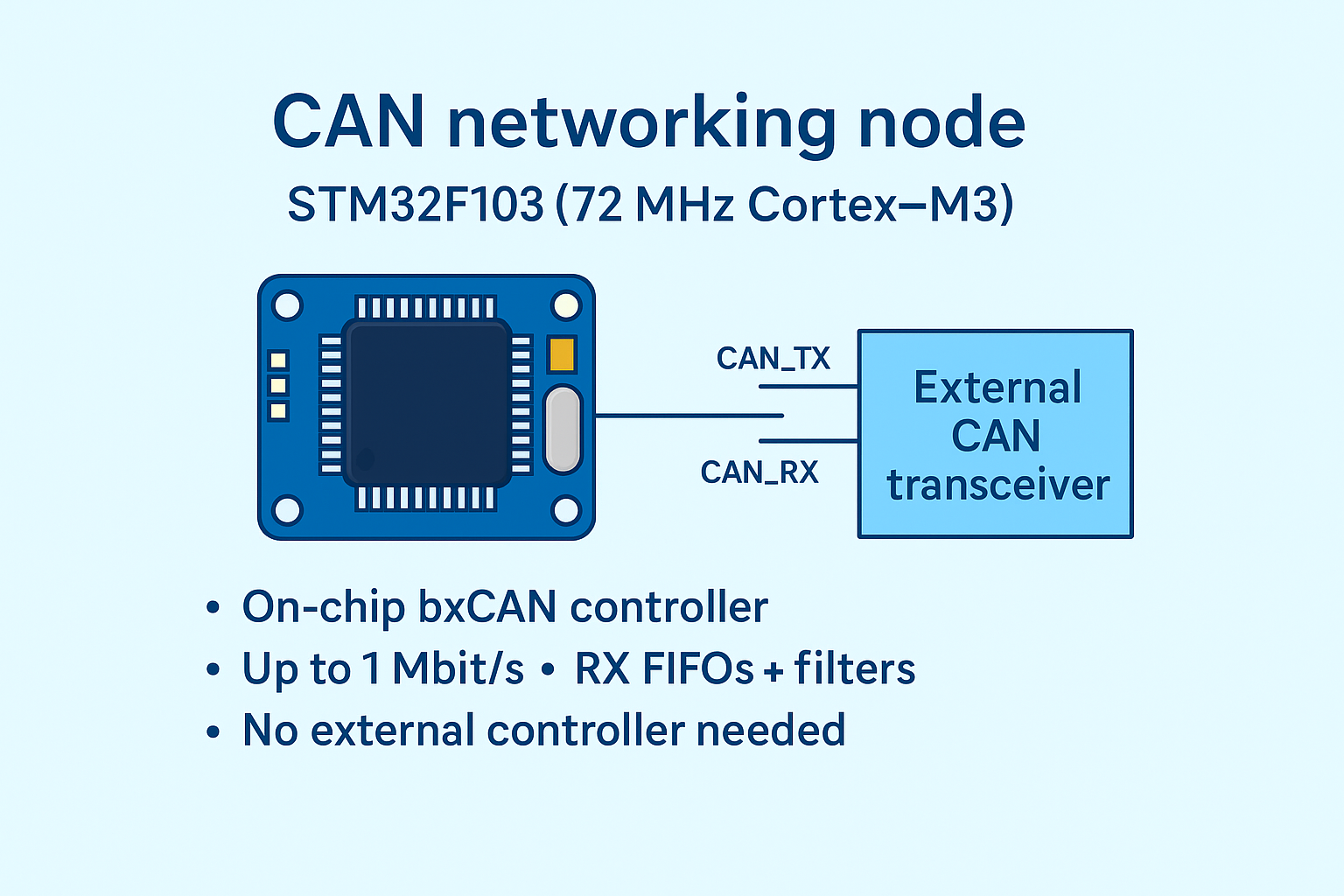
The CAN peripheral can generate interrupts or even use DMA to move frames into RAM, so there’s no SPI latency.
The deeper buffers and richer filter set let the STM32 absorb burst traffic and ignore irrelevant messages at the hardware level.
In the same robotic-arm scenario (500 kbps, ~100 Hz command and feedback loops), the Blue Pill easily handles 500 kbps or 1 Mbps bus speedsMultiple joints updating at 100 HzExtra diagnostics such as temperature, fault codes, or logging traffic
Bench Comparison
Assumptions: 500 kbps, 4–6 nodes, 100 Hz command/feedback, plus some diagnostics.
For one-off prototypes, simple robots, dashboards, or DIY car gauges, an Arduino + MCP2515 CAN module is a sensible, low-friction choice.
For dense CAN networks, multi-axis motion control, or anything likely to become a product, a microcontroller with built-in CAN, such as the STM32F103C8T6, is usually the stronger long-term option.
Alternatives to MCP2515
The MCP2515 is a solid classic CAN controller, but there are strong alternatives if you need more speed, simpler hardware, or higher robustness.
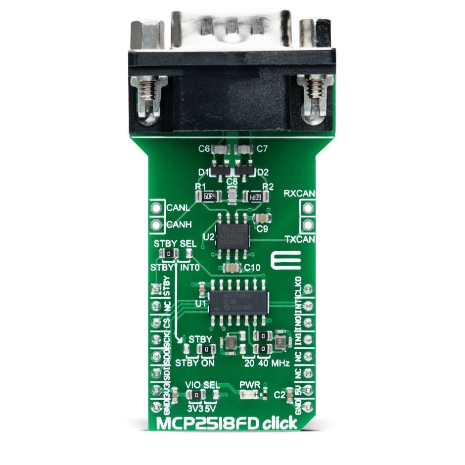
MCP2518FD is the logical upgrade if you want CAN FD:
- Stand-alone controller with SPI, like MCP2515
- Supports CAN FD (up to ~8 Mbps data phase, 64-byte payloads)
- Backward-compatible with classic CAN 2.0B
- More TX/RX buffers and optional internal oscillator
If you’re designing new hardware or expect to see CAN FD in future vehicles or equipment, MCP2518FD is the modern “drop-in” replacement in spirit.
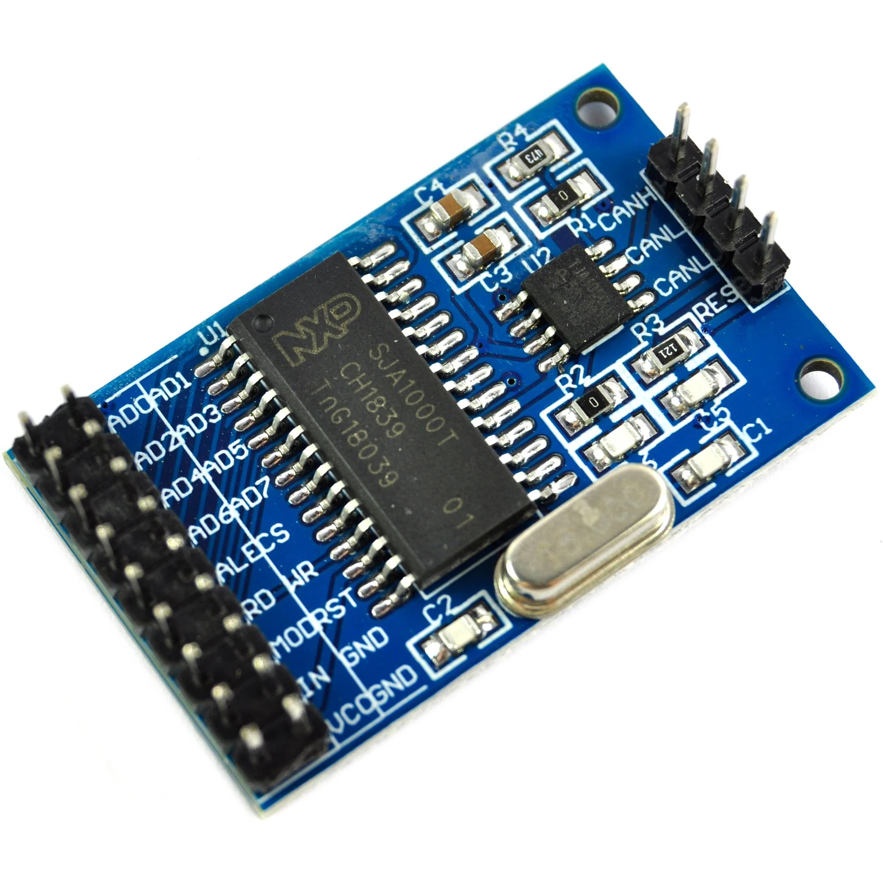
SJA1000 is NXP’s classic external CAN controller:
- Supports CAN 2.0B up to 1 Mbps
- Uses a parallel bus interface, not SPI
- Common in older industrial and PC-based CAN cards
For new hobby or small embedded designs, it’s mostly legacy; MCP2515/MCP2518FD are far easier to integrate via SPI.
-
ATmega32M1 / AT90CAN / PIC18F-K83 / STM32 / ESP32
You can skip external controllers by picking microcontrollers with built-in CAN:
- AVR with CAN: e.g. ATmega32M1, AT90CAN
- PIC18F-K83, PIC24, dsPIC33 with CAN or CAN FD
- STM32 families with CAN / FDCAN (F1, F4, F7, G4, H7, etc.)
- NXP LPC / Kinetis parts with CAN
- ESP32, which already includes a classic CAN (TWAI) controller—only a transceiver is needed
This reduces parts count and improves buffering and latency, but usually means adopting a new toolchain and peripheral API.
-
MCP2551 / MCP2562/3 / SN65HVD230 / ISO1050 / TJA1054
Regardless of controller, you still need a CAN transceiver for CANH/CANL:
- MCP2551 – basic 5 V high-speed CAN transceiver
- MCP2562/3 – newer Microchip parts with better power modes, 3.3 V logic variants
- SN65HVD230/231/232 – popular 3.3 V TI transceivers (great with STM32/ESP32)
- ISO1050, isolated TJA1051/1042, etc. – for industrial/noisy or long-cable environments
- TJA1054 – low-speed / fault-tolerant for specific automotive body networks
For most projects, a standard high-speed transceiver is enough; go isolated or automotive-grade when reliability and EMC are critical.
Final Thoughts
Choosing the right CAN solution depends on how far your project needs to go.
For Arduino-level builds and moderate traffic, the MCP2515 CAN bus module remains a practical, low-cost option that delivers reliable CAN 2.0 communication when wired and terminated correctly.
As your design grows, however, the limits of an external SPI controller become more noticeable: added latency, small receive buffers, and the risk of dropped frames under heavier load.
At that point, moving to a microcontroller with built-in CAN or upgrading to a newer controller like the MCP2518FD often provides better long-term scalability.
Planning ahead helps. If you expect more nodes, higher data rates, or a transition to CAN FD, consider choosing hardware that can grow with your system.
If you are building your own PCB or want a high-quality controller for a long-term design, Flywing Tech offers the MCP2515T-E/ST, a RoHS-compliant 20-TSSOP version of the MCP2515 with full 1 Mbps support.
It pairs perfectly with Flywing’s CAN transceivers, connectors, and wiring accessories, giving you everything you need to build a clean, dependable CAN network without sourcing parts from multiple suppliers.
Frequently Asked Questions (FAQ)
1. What is the MCP2515 and what does it do?
The MCP2515 is a stand-alone CAN 2.0A/B controller from Microchip that connects to a microcontroller over SPI. It handles CAN framing, arbitration, error checking, and filtering, so your MCU only has to send and receive complete CAN frames rather than deal with bit-level protocol details.
2. What’s the difference between the MCP2515 and the CAN transceiver (e.g. TJA1050, MCP2551)?
The MCP2515 is the digital CAN controller; it understands CAN protocol and talks SPI to your MCU. The CAN transceiver (TJA1050, MCP2551, SN65HVD230, etc.) converts those logic-level TX/RX signals to the differential CANH/CANL voltages on the physical bus. Most “MCP2515 CAN bus modules” include both chips on one board.
3. Do I need one MCP2515 per node on the CAN bus?
Yes. Each CAN node that doesn’t have a built-in CAN controller needs its own MCP2515 (or similar controller) plus a transceiver. You can’t share a single MCP2515 across multiple MCUs on the same bus; every logical CAN node requires its own CAN controller.
4. How do I wire the MCP2515 CAN bus module to an Arduino Uno?
For an Arduino Uno, the common connections are:
- VCC → 5V
- GND → GND
- CS → D10
- MOSI → D11
- MISO → D12
- SCK → D13
- INT → D2
Then connect CANH to CANH and CANL to CANL between modules, ensure a common ground, and enable the 120 Ω termination at the ends of the bus.
5. Why is my MCP2515 CAN bus module not working with Arduino?
The most common causes are:
- The library is configured for the wrong crystal (16 MHz vs 8 MHz)
- Different CAN baud rates set on each node
- Missing or incorrect termination (120 Ω at both ends only)
- CANH/CANL swapped or no common ground
- INT pin not wired or wrong CS pin defined in code
Checking those points solves the majority of “MCP2515 Arduino” issues.
6. What is the maximum speed and cable length for an MCP2515 CAN network?
The MCP2515 supports classic CAN speeds up to 1 Mbps. As with any CAN controller, usable cable length depends on bit rate and wiring quality: typical rules of thumb are around 40 m at 1 Mbps and up to ~1000 m at 50 kbps with proper twisted-pair cabling and termination. The limitation is the CAN bus itself, not specifically the MCP2515.
7. How does the MCP2515 compare to a microcontroller with built-in CAN, like STM32F103 (Blue Pill)?
Functionally they both speak CAN 2.0B, but the architecture is different:
- MCP2515 + MCU: external controller over SPI, 2 RX buffers, extra latency and more parts
- STM32F103: built-in bxCAN, deeper RX FIFOs, more filters, no SPI hop, fewer ICs
For light-to-moderate traffic and simple projects, MCP2515 modules are ideal. For higher bus load, tighter real-time control, or more professional designs, built-in CAN (like STM32F103C8T6) generally offers better performance and simpler hardware.
8. Should I use MCP2515 or MCP2518FD for new designs?
If you only ever need classic CAN at ≤1 Mbps, MCP2515 is fine and widely supported. If you think you may need CAN FD (higher data rates and 64-byte payloads) or want a more future-proof controller, MCP2518FD is the better choice. It’s SPI-based like the MCP2515 but adds CAN FD capability and more internal buffering.
9. Can I use MCP2515 with ESP32 or should I use the ESP32’s built-in CAN (TWAI)?
You can use MCP2515 with ESP32 over SPI, but in many cases you don’t need to. The ESP32 already has a built-in CAN (TWAI) controller, so you usually only need to add a CAN transceiver (e.g. SN65HVD230) and configure TWAI in software. MCP2515 is more useful when the MCU truly has no CAN peripheral.
10. How many messages can the MCP2515 handle under heavy load?
The MCP2515 has two receive buffers. At high bus utilization, if frames arrive faster than your MCU can read them over SPI, it will drop additional frames. For moderate traffic (e.g. sensor data at 10–100 Hz on a reasonably loaded bus), it performs well. For very heavy traffic or tight real-time constraints, a built-in CAN controller with deeper FIFOs is more suitable.
11. What should I look for in cables and connectors for MCP2515 CAN projects?
Use:
- Twisted-pair cable with ~120 Ω characteristic impedance
- Proper 120 Ω termination at both ends of the bus
- Solid, locking connectors (e.g. OBD-II, DB9, industrial circular) instead of loose jumper wires
Good physical-layer design often matters more for reliability than the specific CAN controller. That’s where sourcing quality connectors, harnesses, and pre-terminated cables—like those in a Flywing Tech style catalog—can make a big difference.