Wireless modules are everywhere, from home automation to industrial automation and amateur electronics. The CC1101 and the nRF24L01 are two of the most commonly used low-power RF modules. Even though both of them enable the microcontrollers to transmit and receive data wirelessly, they serve entirely different purposes.
Fly-Wing Tech has various RF modules, and in this article, we will discuss two different types of RF modules, CC1101 and nRF24L01, and their features and use cases.
What is the CC1101?
CC1101 is a sub-GHz RF transceiver whose wireless system needs a high range of communication and low energy consumption. It operates in the lower sections of the ISM – 315 MHz, 433 MHz, 868 MHz, and 915 MHz with excellent obstacle penetration and low path loss compared to 2.4GHz. A connection can be simply adjusted for either maximum range or the minimum power expended by the battery. This flexibility comes from the CC1101’s modulation techniques, commonly implemented using modules like CC1101RGPR.
CC1101 Pinout
CC1101 Wiring Diagram
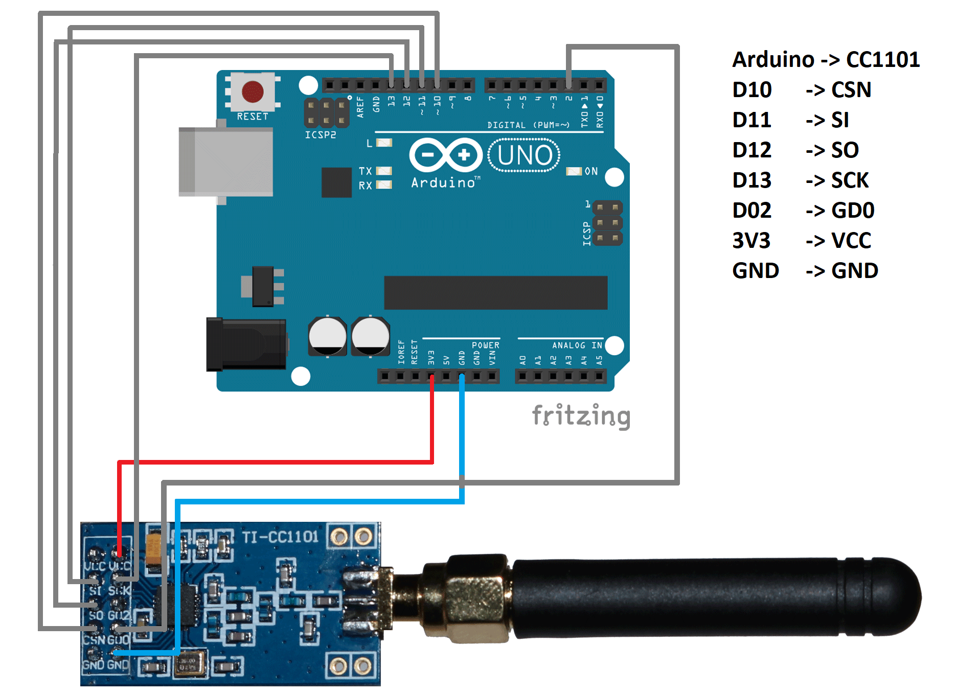
#include <ELECHOUSE_CC1101_SRC_DRV.h>

void setup() {
  Serial.begin(9600);
  ELECHOUSE_cc1101.Init();
  ELECHOUSE_cc1101.setMHZ(433);
}

void loop() {
  const char msg[] = "Hello CC1101";
  ELECHOUSE_cc1101.SendData(msg, sizeof(msg));
  delay(500);
}
What is the nRF24L01?
The nRF24L01 is a 2.4 GHz RF transceiver that Nordic Semiconductor developed to be used in short and medium-range communication systems.
Read more: Nordic Semiconductor nRF24L01P-R-RF
The module is effective for systems that require high speed, responsiveness, and efficiency of energy consumption. It runs on the international 2.4 GHz ISM band and thus provides high data rates when compared to sub-GHz modules and could send small packets nearly immediately; therefore, it is applicable to real-time systems. The module has inbuilt features such as automatic acknowledgement, automatic retransmission of packets, and data pipes management, and thus devices are capable of exchanging information with high reliability without the need to manually work in code.
Though nRF24L01 is not as good as sub-GHz modules with regard to raw distance and wall penetration, its performance, speed, and ease of use render it among the most favoured 2.4 GHz wireless modules in hobbyist as well as small-scale commercial applications.
nRF24L01 Pinout
The standard nRF24L01 module contains eight pins that are available on one side of the PCB. It has a communication based on SPI, and only power, control, and data transfer pins. Each pin has a clear purpose as explained in the table below:
nRF24L01 Wiring Diagram
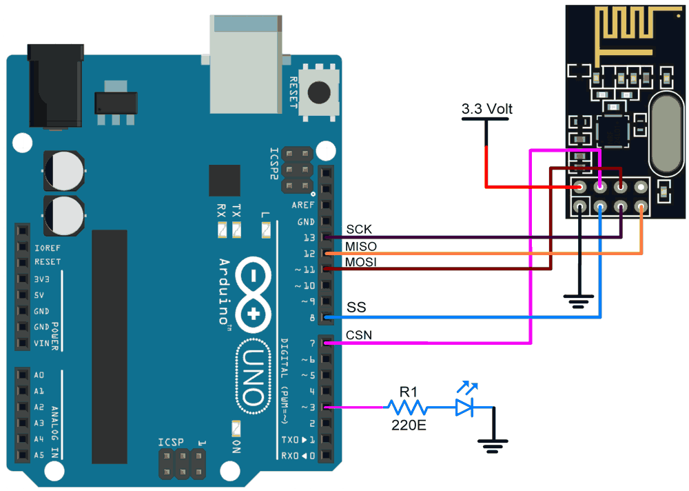
#include <SPI.h>
#include <nRF24L01.h>
#include <RF24.h>

RF24 radio(7, 8);
const byte address[6] = "00001";

void setup() {
  radio.begin();
  radio.openWritingPipe(address);
  radio.setPALevel(RF24_PA_LOW);
  radio.stopListening();
}

void loop() {
  const char msg[] = "Hello NRF";
  radio.write(&msg, sizeof(msg));
  delay(500);
}
CC1101 vs nRF24L01: Detailed Comparison
Frequency
The CC1101 uses sub-GHz ISM /SRD frequencies – 315 MHz, 433 MHz, 868 MHz and 915 MHz. It can be programmed to work in broader factors: 300-348 MHz, 387-464 MHz, and 779-928 MHz.
The nRF24L01 (also known as the nRF24L01+) operates at 2.4 GHz (2.400-2.4835 GHz) in the world.
Implication: CC1101 has a lower frequency, which implies it penetrates walls/obstacles better than nRF24L01 and has higher range potential, but nRF24L01 has greater bandwidth and is more vulnerable to interference and has less ability to penetrate the barriers.
Application
The CC1101 wireless chip supports ultra-low-power wireless sensor networks, industrial monitoring, metering, home/building automation, and communication systems in ISM/SRD bands.
The nRF24L01, on the other hand, is the best choice for fast-data, short/medium range wireless links: among game controllers, PC peripherals, remote controls, home automation, toys, sensors and RF asset tracking.
For industrial automation, large-scale IoT deployment, and higher RF applications, modules like Digi XBee 3 2.4GHz RF transceiver module will provide secure communication and long-term industrial reliability.
Similarly, a common choice for BLE-enabled IoT products is Microchip RN4871 BLE RF transceiver module, which supports fast prototyping.
Distance Range
The sensitivity figures (-116 dBm at 0.6 kBaud in 433 MHz) provided by the CC1101 point to its capability for long range.
The nRF24L01 is normally around 50-100 meters in range for standard hobby usage with the typical on-board antenna. In comparison, open space/PA-LNA variants might offer up to several hundred meters (or even more). One account, for instance, says “If used in open space and with lower baud rate its range can reach up to 100 meters.”
Interpretation: The CC1101 offers a distinct advantage in terms of raw range and penetration (sub-GHz). The nRF24L01 can still cover considerable distances, but is more prone to the effects of the environment, obstacles, and interference.
Data Rate
The CC1101 transceiver is capable of operating at a range of data rates from 0.6 kbps to 600 kbps (0.6 kb/s to 600 kb/s).
As per the specifications, nRF24L01 can deliver air data rates of 250 kbps, 1 Mbps, and 2 Mbps.
Inference: nRF24L01 undoubtedly provides higher data throughput, which is an advantage in applications with more frequent or bulk data transfers. While CC1101 sacrifices speed for longer range and low power operation.
Power Consumption
CC1101: The RX current is about 14.7 mA (1.2 kBaud at 868 MHz), while the TX current for a +12 dBm output is between 30-35 mA, depending on the voltage and other factors. The 200 nA sleep current is considered the maximum for the sleep mode.
nRF24L01: The output power for the typical TX current is around 11.3 mA at zero dBm, and RX is around 12.3 mA at 2 Mbps, with the power-down modes consuming less than a microamp (900 nA) and standby drawing around 22 µA.
Furthermore, engineers may also choose the Silicon Labs MGM111A256V2 multi-protocol RF transceiver module for compact and low-power IoT designs.
Summary: Current draw is still low in both designs; however, the nRF24L01 is the one that consumes less power during the active TX/RX phase at moderate power levels, although in a higher-frequency band. The ultra-low-power sensor application where infrequent updates are required justifies CC1101’s deep-sleep and sub-GHz advantages.
Microcontroller Compatibility
CC1101: More configuration is needed (register setup for modulation, frequency, packet handling), and it is usually a more custom and optimized low-power application.
nRF24L01: Libraries are available everywhere, packet handling is done automatically (Enhanced ShockBurst™), making the integration of the module easier for hobbyists and prototyping.
Conclusion: If you know RF settings and low-power design, CC1101 is the one that gives the most freedom. If you are looking for a fast setup with lots of libraries/support, nRF24L01 is the one that wins in integration ease.
Antenna Design
CC1101: Due to the use of sub-GHz frequencies, the antenna size is usually the larger one (for instance, quarter-wave lengths ~170 mm for 433 MHz), and the layout of the board and the matching network become very important. TI has provided antenna matching and PCB layout guidelines in its datasheet.
nRF24L01: It is working at the frequency of 2.4 GHz, which means the design of antennas is less bulky (quarter-wave ~31 mm), and numerous devices are equipped with either a trace antenna on the PCB or a little whip antenna. Nonetheless, the frequency band of 2.4 GHz is much more packed than the other one, and the positioning of the antenna as well as the surrounding matter a lot.
Tip: A module cannot perform well without a good antenna design. Proper impedance matching, ground plane, and clearance are essential. Sub-GHz modules like the CC1101 are less affected by obstacles, while 2.4 GHz modules like the nRF24L01 can lose a lot of range if the antenna or PCB layout is poor.
Comparision Table
Pros and Cons of CC1101 and nRF24L01
CC1101
nRF24L01
Troubleshooting Guide
CC1101 Common Issue
Power Stability
The CC1101 is very sensitive to supply noise and voltage ripple. Thus, to ensure stable and clean operation, you need to use a clean, regulated 3.3V power supply.
Antenna Tuning and Orientation
Most CC1101 range issues come from incorrect or poorly tuned antennas.
To fix this, you need to use a quarter-wave antenna for your frequency. Also, you need to keep the antenna vertical and away from metal.
nRF24L01 Troubleshooting
Power Sensitivity
During transmission, the nRF24L01 module is power sensitive, meaning it draws fast current spikes, and the microcontroller’s 3.3V regulator is not enough. This causes packet loss, voltage drops, random freezes and also no acknowledgement errors.
Solution:
To fix this error, you need to add decoupling capacitors: 0.1 μF ceramic and 10 μF electrolytics directly across the nRF25L01 Vcc-Gnd pins.
Also, do not power the PA+ LNA version from Arduino’s 3.3V pin. It is because Arunino’s regulator supplies only ~50 mA while the high power modules draw 100-250 mA.
For this, you need to use a separate 3.3V LDO regulator with a shared ground.
RF Interference and Channel Congestion
The 2.4 GHz band is a crowded band, and poor channel selection can severely reduce the range.
Solution
To improve this RF performance:
- You need to test multiple nRF channels, avoiding Wi-Fi overlap.
- Need to adjust antenna placement by maintaining at least 1-1.15cm clearance from cables, batteries, and PCBs.
If the module still performs poorly, try to add the ground plane beneath the module. Shield the noisy components using copper tape or a small RF shield.
nRF24L01 vs nRF24L01+
CC1101 vs CC1352/CC1350
CC1352 and CC1350 are the modern successors of CC1101 that can combine both sub-GHz and 2.4 GHz in a single product. As compared to CC1101:
- CC1350/1352 contains the ARM Cortex, so there is no need for an external MCU in power IoT devices.
- They have a better RF front-end design, which provides improved receiver sensitivity and ultra-low power standby modes.
- They are a better choice for modern dual-band IoT products that require long-range communication with 2.4GHz connectivity in a single device.
Real Test Comparison
To provide a more practical, real-world comparison, both modules were tested under identical conditions.
For example, let’s check the test condition below:
Open field environment with controller Arduino Uno. A simple “Hello World” data packet was sent every 1000ms.
Modules: CC1101 and NRF24L01
Distance Test: CC1101 had stable data up to 300m, whereas NRF24L01 has stable data up to 50-60m. CC1101 has a lesser packet loss from 0-10% whereas nRF24L01 has a greater packet loss that fails after 100m.
The test shows CC1101 performs better in terms of range and reliability compared to nRF24L01.
When to Choose CC1101 vs nRF24L01?
Consider the CC1101 module when:
- You need ultra-low power Operation, and thus the battery life is a priority.
- You require long-range communication that could go from meters to several kilometres.
- Your system operates in sub-GHz frequency, and you want them with low path loss.
- You need flexible modulation options, including GFSK, OOK, MSK and 2-FSK.
Consider the nRF24L01 module when:
- You need faster data transmission (1-2 Mbps) for short distances (10-60 meters).
- Your project requires low latency for a real-time control system.
- You want a simple library with a quick prototype, along with fast development.
- You need built-in auto-ack (automatic acknowledgement) and multi-channel – multi-point to single-point communication.
Conclusion
Thus, both modules have their strengths and weaknesses, and the right choice depends on the project’s needs. If you need help choosing the right module or designing your next wireless project, FlyWing Tech is here to guide you.
FAQs
The CC1101 on the Flipper Zero is a small radio chip that transceives sub-GHz signals. This helps the flipper zero to work with things like wireless sensors, remotes, etc. And with the help of Flipper Zero, you can simply plug-and-play through the expansion port and help add custom hardware through GPIO pins.
CC1101 works with both Arduino and ESP32. These devices make communication through SPI and the available libraries, which allow communication with RF modules and other wireless systems.
No, nRF24L01 cannot transmit audio and video signals. It is because of its limited data rates. The module is a low-power transceiver that sends small data packets and is not suitable for sending higher bandwidth data like video and audio.
The best choice between CC1101 and nRF24L01 depends on the use case scenario, like the communication range, frequency and the requirements of the project. CC1101 is a good choice for long-range communication, while nRF24L01 is good for short-range and high-speed applications.
This happens because of the instability of the 3.3V power. The module freezes when the Arduino can’t supply enough current, there’s no capacitor, or the wires are too long. Thus, in order to address this issue, adding a 0.1µF + 10µF capacitor and using a stable 3.3V regulator can help.
To improve the range of CC1101 without increasing transmit power, you can use a proper quarter-wave antenna, lower the data rate, narrow the bandwidth, improve grounding, and reduce interference. These help to boost sensitivity and range without raising output power.
References:
- Texas Instruments. (2013). CC1101 Low-Power Sub-1 GHz RF Transceiver (Rev. E) [Datasheet]. https://www.ti.com/lit/ds/symlink/cc1101.pdf
- Nordic Semiconductor. (2007). nRF24L01+ Product Specification v1.0 [Datasheet]. https://cdn.sparkfun.com/assets/3/d/8/5/1/nRF24L01P_Product_Specification_1_0.pdf
- Nordic Semiconductor. (2006). nRF24L01 Product Specification v2.0 [Datasheet]. https://cdn.sparkfun.com/datasheets/Wireless/Nordic/nRF24L01_Product_Specification_v2_0.pdf
- https://cdn.sparkfun.com/assets/3/d/8/5/1/nRF24L01P_Product_Specification_1_0.pdf