Resistors are one of the most important components in electronic circuits, devices, and projects. They have two terminals, and their primary role is to limit or regulate the flow of current within a circuit. If you look closely at a resistor, you’ll notice different colored bands printed on its body. These are resistor color codes, which indicate the resistance value, tolerance, and sometimes the temperature coefficient of the resistor.
In this guide, we will explore the structure of resistors, understand resistor color codes in detail, and learn how to read them accurately
Structure of a Resistor
Resistors are among the most common electronic components we use, and we cannot complete our circuits and projects without them. The primary function of a resistor is to control the current flow in a circuit. A resistor has two pins, a circular shape, and a small size, which make its connection with the circuit easy. Different color bands on the resistor surface help to identify the resistor easily. These color bands indicate the resistance value, which is important for proper resistor connections in the circuit. Based on power rating and applications, resistors come in different shapes and sizes. Small circuits use carbon film resistors, while engineers connect high-power resistors in high-current circuits with heat dissipators, as they generate heat during operation.

Resistor Color Codes Understanding
The resistor color code uses a standardized system of colored bands to indicate a resistor’s resistance value, tolerance, and temperature coefficient.In this system, manufacturers print different colored lines or bands on resistors, with each color representing a specific numerical value.
Resistors typically have 4, 5, or 6 color bands, depending on the required level of accuracy in the circuit. The first two or three bands represent significant digits, read from left to right. The following bands indicate the multiplier and tolerance. In some special resistor types, an additional band is used to specify the temperature coefficient or reliability.
According to the international standard IEC 60062, each color band corresponds to a predefined value. The multiplier band represents a power of ten, while the tolerance band shows the allowable percentage variation in the resistor’s value, depending on circuit requirements.
Understanding the resistor color coding system is essential for accurately identifying resistor values and ensuring their proper use in circuits. For this reason, all electronics engineers and students should be familiar with the resistor color code.

Resistors’ color code reading order
When measuring resistor values using color bands, the color code sequence may sometimes be misread, leading to incorrect results. To avoid errors, engineers follow specific methods to correctly identify resistor color codes.
The first step is to locate the tolerance band, as it helps determine the correct reading direction. Tolerance bands are typically gold, silver, or brown. Gold and silver are less common as the first band, so their presence usually indicates the tolerance band.
However, brown can represent both a significant digit and a tolerance band, which sometimes makes it confusing. In such cases, spacing between the bands can help. For example, in a 5-band resistor, the gap between the 4th and 5th bands is usually larger than the spacing between the earlier bands, helping to identify the tolerance band position.
If spacing does not provide enough clarity, the sequence itself can be used to confirm the value. For instance:
-
Brown, Black, Black, Yellow, Brown → Resistance = 100 × 10,000 = 1 MΩ with ±1% tolerance.
-
Brown, Yellow, Black, Black, Brown → Resistance = 140 × 1 = 140 Ω with ±1% tolerance.
By carefully checking the tolerance band and color sequence, engineers can accurately determine resistor values and avoid misinterpretation.
How to read resistor color codes?

Click the image to enlarge for a clearer view of the resistor color codes
Reading resistor color codes may seem difficult at first, but the process is actually quite simple. To begin, identify the correct orientation of the resistor. Typically, the bands are read from left to right, starting with the band closest to the edge.
As explained earlier, resistors can have different numbers of color bands depending on their purpose.
-
4-band resistors are commonly used for general applications.
-
5-band resistors offer higher accuracy.
-
Furthermore, 6-band resistors are used in precision applications where the temperature coefficient must also be specified.
By understanding these variations, you can quickly and accurately interpret resistor values for any circuit.
| 0 | 1 | 2 | 3 | 4 | 5 | 6 | 7 | 8 | 9 |
| Black | Brown | Red | Orange | Yellow | Green | Blue | Violet | Gray | White |
Let’s explain each band to understand the resistor color code.
4-Band Resistor Color Code
Four-band resistors are the most commonly used type, and they are identified by four different color bands.
-
The first band represents the first significant digit of the resistance value.
-
The second band represents the second significant digit.
-
The third band is the multiplier, which indicates the power of ten used to multiply the first two digits.
-
The fourth band shows the tolerance, which specifies the possible percentage variation from the nominal resistance value.
Example of a four-band resistor
Consider a resistor with the color bands brown, black, red, and gold:
-
Brown = 1 (first digit)
-
Black = 0 (second digit)
-
Red = multiplier of 10²
-
Gold = tolerance of ±5%
This gives a resistance value of 1,000 Ω (1 kΩ) with a tolerance of ±5%.
5-Band Resistor Color Code
As a result, a five-band resistor provides higher accuracy by using three significant digits instead of two. The color bands are interpreted as follows:
-
1st band: first significant digit
-
2nd band: second significant digit
-
3rd band: third significant digit
-
4th band: multiplier (power of ten)
-
5th band: tolerance (percentage variation in resistance)
Example of a five-band resistor
Consider a resistor with the color bands red, violet, black, brown, and gold:
-
Red = 2 (first digit)
-
Violet = 7 (second digit)
-
Black = 0 (third digit)
-
Brown = multiplier of 10¹
-
Gold = tolerance of ±5%
This gives a resistance value of 2,700 Ω (2.7 kΩ) with a tolerance of ±5%.
6-Band Resistor Color Code
A six-band resistor is used in advanced applications where temperature stability is an important factor. The first five bands are interpreted the same way as in a five-band resistor. Additionally, the sixth band represents the temperature coefficient, measured in parts per million per degree Celsius (ppm/°C)
-
1st band: first significant digit
-
2nd band: second significant digit
-
3rd band: third significant digit
-
4th band: multiplier (power of ten)
-
5th band: tolerance (percentage variation)
-
6th band: temperature coefficient (ppm/°C)
Example of a six-band resistor
Consider a resistor with the color bands yellow, violet, black, red, brown, and blue:
-
Yellow = 4 (first digit)
-
Violet = 7 (second digit)
-
Black = 0 (third digit)
-
Red = multiplier of 10²
-
Brown = tolerance of ±1%
-
Blue = temperature coefficient of 10 ppm/°C
This resistor has a resistance value of 47,000 Ω (47 kΩ), with a tolerance of ±1% and a temperature coefficient of 10 ppm/°C.
Resistor Color Code Chart
| Color | Digit | Multiplier | Tolerance |
Temp. Coefficient (ppm/°C)
|
| Black | 0 | ×1 (10⁰) | — | 250 |
| Brown | 1 | ×10 (10¹) | ±1% | 100 |
| Red | 2 | ×100 (10²) | ±2% | 50 |
| Orange | 3 | ×1,000 (10³) | — | 15 |
| Yellow | 4 | ×10,000 (10⁴) | — | 25 |
| Green | 5 | ×100,000 (10⁵) | ±0.5% | — |
| Blue | 6 | ×1,000,000 (10⁶) | ±0.25% | 10 |
| Violet | 7 | ×10,000,000 (10⁷) | ±0.1% | 5 |
| Gray | 8 | ×100,000,000 (10⁸) | ±0.05% | — |
| White | 9 | ×1,000,000,000 (10⁹) | — | — |
| Gold | — | ×0.1 (10⁻¹) | ±5% | — |
| Silver | — | ×0.01 (10⁻²) | ±10% | — |
| No Color | — | — | ±20% | — |
SMD Resistor Color Code Reading
SMD resistors use three main coding systems: the 3-digit system, the 4-digit system, and the EIA-96 system.
3-Digit and 4-Digit Code Systems
In the 3-digit and 4-digit systems, the first two or three digits represent the significant figures of the resistance value. Meanwhile, the last digit indicates the number of zeros (the multiplier).
Examples:
-
A code of 7500 means 750 × 10 = 7,500 Ω.
-
A code of 103 means 10 × 10³ = 10,000 Ω (10 kΩ).
For resistance values below 10 ohms, the letter R is used to represent the decimal point. For example, a resistor marked 8R2 has a resistance value of 8.2 Ω.
EIA-96 Code System for Precision Resistors
The EIA-96 system is used for precision resistors with ±1% tolerance. This system provides a wide range of resistance values with high accuracy. In this method, the first two characters are taken from the E96 code chart, and the third character indicates the multiplier.
Example:
A code of 54B corresponds to a base value of 357 (from the E96 chart), and the letter B represents a multiplier of 10. Therefore, the resistance value is 3,570 Ω (3.57 kΩ) with a tolerance of ±1%.
| Code | Value (Ω) | Code | Value (Ω) | Code | Value (Ω) | Code | Value (Ω) |
| 1 | 100 | 25 | 178 | 49 | 316 | 73 | 562 |
| 2 | 102 | 26 | 182 | 50 | 324 | 74 | 576 |
| 3 | 105 | 27 | 187 | 51 | 332 | 75 | 590 |
| 4 | 107 | 28 | 191 | 52 | 340 | 76 | 604 |
| 5 | 110 | 29 | 196 | 53 | 348 | 77 | 619 |
| 6 | 113 | 30 | 200 | 54 | 357 | 78 | 634 |
| 7 | 115 | 31 | 205 | 55 | 365 | 79 | 649 |
| 8 | 118 | 32 | 210 | 56 | 374 | 80 | 665 |
| 9 | 121 | 33 | 215 | 57 | 383 | 81 | 681 |
| 10 | 124 | 34 | 221 | 58 | 392 | 82 | 698 |
| 11 | 127 | 35 | 226 | 59 | 402 | 83 | 715 |
| 12 | 130 | 36 | 232 | 60 | 412 | 84 | 732 |
| 13 | 133 | 37 | 237 | 61 | 422 | 85 | 750 |
| 14 | 137 | 38 | 243 | 62 | 432 | 86 | 768 |
| 15 | 140 | 39 | 249 | 63 | 442 | 87 | 787 |
| 16 | 143 | 40 | 255 | 64 | 453 | 88 | 806 |
| 17 | 147 | 41 | 261 | 65 | 464 | 89 | 825 |
| 18 | 150 | 42 | 267 | 66 | 475 | 90 | 845 |
| 19 | 154 | 43 | 274 | 67 | 487 | 91 | 866 |
| 20 | 158 | 44 | 280 | 68 | 499 | 92 | 887 |
| 21 | 162 | 45 | 287 | 69 | 511 | 93 | 909 |
| 22 | 165 | 46 | 294 | 70 | 523 | 94 | 931 |
| 23 | 169 | 47 | 301 | 71 | 536 | 95 | 953 |
| 24 | 174 | 48 | 309 | 72 | 549 | 96 | 976 |
British Standard Code (BS 1852)
For larger power resistors, the resistor color code is not required because the tolerance and power rating are usually printed directly on the resistor’s surface.
If a resistor becomes rusted or discolored, its resistance value can be difficult to read. To solve this issue, the BS1852 coding system was introduced, making it easier to identify resistance values and related factors.
In this system:
-
M is used to indicate the decimal point.
-
R is used as a multiplier equal to or less than one.
-
K denotes kilo-ohms (thousands).
Examples of BS1852 resistor values:
-
1 MΩ = 1M0
-
470 KΩ = 0M47 or 470K
-
47 KΩ = 47K
-
4.7 KΩ = 4K7
-
1.0 KΩ = 1K0
-
0.47 Ω = 0R47 or R47
-
1.0 Ω = 1R0
-
47 Ω = 47R
-
470 Ω = 0K47 or 470R
Manufacturers also indicate tolerance with a letter written alongside the resistance value. For instance, the marking 47K J specifies a resistor of 47 kΩ, where the letter “J” represents the tolerance code. Therefore, this system helps quickly identify resistance and tolerance values.
Different letters are used to denote the tolerance of resistors:
-
B = ±0.1%
-
C = ±0.25%
-
D = ±0.5%
-
F = ±1%
-
G = ±2%
-
J = ±5%
-
K = ±10%
-
M = ±20%
For example, in the case of a resistor marked 47K J, the letter J indicates that the resistor has a tolerance of ±5%. Therefore, this marking helps users quickly identify the resistor’s precision level.

- We uses Different alphabets to denote the tolerance of resistors, such as
| Code | Tolerance |
| B | ±0.1% |
| C | ±0.25% |
| D | ±0.5% |
| F | ±1% |
| G | ±2% |
| J | ±5% |
| K | ±10% |
| M | ±20% |
In the above example, we used the letter J, which means this resistor has a tolerance of 5%.
Importance of Resistors in Electronics
A resistor is a fundamental component in electronic circuits, playing a crucial role in ensuring they operate safely and effectively. Understanding the correct resistance value is crucial—without it, you cannot achieve the desired performance in a circuit.
Using a resistor with an incorrect rating can cause excessive current to flow. As a result, the circuit and other connected components, such as LEDs, may become damaged. Moreover, in addition to current control, resistors are essential for voltage regulation, signal conditioning, and timing functions, making them a core part of many electronic systems.
Technicians often use color-coding techniques to determine the resistance value. Alternatively, they can use instruments like multimeters or ohmmeters. To measure resistance with a multimeter, simply set the device to resistance mode and connect the probes to the resistor terminals. The resistance value, measured in ohms, will appear on the display.
In addition, technicians measure resistance to diagnose and identify damaged components, especially those affected by environmental factors, and replace them to maintain proper circuit functionality.
Some Errors and How to Avoid Them
Errors in reading resistors often stem from a lack of proper skills or environmental factors. Here are some common mistakes:
1. Misinterpreting Colors
Under poor lighting conditions, some resistor colors—such as red, orange, blue, and green—can appear similar, leading to incorrect readings. Always ensure proper lighting when identifying color bands, and verify the value with a multimeter to avoid mistakes.
2. Reading in the Wrong Direction
Reading a resistor from the wrong end can result in inaccurate values.Position the tolerance band (usually gold or silver) on the far right. Flipping the resistor will cause the color code to give an incorrect value.
3. Temperature Coefficient Misunderstanding
High-precision resistors often include an additional color band to indicate the temperature coefficient. This specification can affect resistance under varying temperatures. Therefore, always consult the manufacturer’s datasheet or manual before reading such resistors to ensure accuracy.
High Voltage Resistors Markings
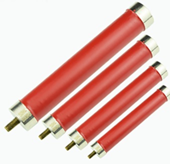
When designing high-voltage resistors, special considerations are required. Specifically, in such resistors, silver and gold color bands are not used, as they could create inadvertent combinations of metallic components in the external coating. As a result, these metallic particles may pose safety hazards under high-voltage conditions. Instead, yellow and gray bands are used to mark high-voltage resistors. Consequently, this approach not only distinguishes them from conventional color code systems but also reduces the risk of misidentification.
Furthermore, high-voltage applications demand additional features in resistors, including optimized core design and the use of proper insulating materials. These resistors must therefore provide excellent insulation properties and withstand voltage stress safely. To achieve this, manufacturers apply specialized parameters, materials, and production processes, thereby ensuring reliable operation even during sudden voltage spikes or overheating.
Applications of high-voltage resistors include:
-
Power management systems
-
Industrial control systems
-
Medical devices
These design features make high-voltage resistors safe, stable, and suitable for demanding electrical environments.
Standard Resistor E-Series
-
It is not practical to produce every possible resistance value for industrial use. To address this, resistors are manufactured in specific groups known as the E-series, which provide a set of standard resistor values for each decade.
-
The letter E is followed by a number that represents the total number of values within one decade of the series. The most commonly used resistor series are:
| E-Series | Values per Decade |
Typical Tolerance
|
| E6 | 6 | ±20% |
| E12 | 12 | ±10% |
| E24 | 24 | ±5% |
| E48 | 48 | ±2% |
| E96 | 96 | ±1% |
| E192 | 192 |
±0.5%, ±0.25%, ±0.1% (ultra precision)
|
Standard Resistor Values in E6, E12, E24 Series are as
| Series (Tol.) | Values per Decade |
Standard Values (Ω from 1 to 10)
|
| E6 (±20%) | 6 |
1.0, 1.5, 2.2, 3.3, 4.7, 6.8
|
| E12 (±10%) | 12 |
1.0, 1.2, 1.5, 1.8, 2.2, 2.7, 3.3, 3.9, 4.7, 5.6, 6.8, 8.2
|
| E24 (±5%) | 24 |
1.0, 1.1, 1.2, 1.3, 1.5, 1.6, 1.8, 2.0, 2.2, 2.4, 2.7, 3.0, 3.3, 3.6, 3.9, 4.3, 4.7, 5.1, 5.6, 6.2, 6.8, 7.5, 8.2, 9.1
|
1k Ohm Resistor Color Code
-
A one-kilohm resistor can be identified using the standard four-band color code system. This method makes it easy to determine resistance and tolerance without the need for measuring instruments.
-
Brown = 1 (first digit)
-
Black = 0 (second digit)
-
Red = multiplier of 100 (10²)
-
Gold = tolerance of ±5%
-
In this system, a 1 kΩ resistor is represented by the color bands brown, black, red, and gold:
-
This gives a resistance value of 1,000 Ω (1 kΩ) with a tolerance of ±5%.

| Band | Color |
Digit/Multiplier/Tolerance
|
| 1st Band | Brown | 1 |
| 2nd Band | Black | 0 |
| 3rd Band | Red | Multiplier: 100 |
| 4th Band | Gold | Tolerance: ±5% |
10K/10K Ohm Resistor Color Code

| Band | Color | Value |
| 1st | Brown | 1 |
| 2nd | Black | 0 |
| 3rd | Orang | 1000 |
| 4th | Gold | ±5% |
The calculation of a 10 kΩ resistor using the color code system is straightforward. This resistor has the color bands brown, black, orange, and gold, which make it easy to determine its value with a tolerance of ±5%.
-
Brown = 1 (first digit)
-
Black = 0 (second digit)
-
Orange = multiplier of 1,000 (10³)
-
Gold = tolerance of ±5%
This gives a resistance value of 10,000 Ω (10 kΩ) with ±5% tolerance.
Resistance Measurement with a Multimeter
A multimeter provides a simple and accurate method for measuring resistance. For example, when measuring a 1 kΩ resistor, set the meter to ohm mode, typically using the 2k or 20k range.
Moreover, for an accurate reading, always disconnect the resistor from the circuit before testing.. Connect the meter probes to each end of the resistor—polarity does not matter for standard resistors.
A properly working 1 kΩ resistor should measure close to 1,000 Ω, depending on its tolerance rating:
-
With a ±5% tolerance (gold band): value will range from 950 Ω to 1,050 Ω
-
With a ±1% tolerance (brown band): value will range from 990 Ω to 1,010 Ω
In fact, these values can also be confirmed using the resistor’s color bands.
Practical Resistor Selection
Until now, we have studied resistor color codes and charts in theory. However, practical examples make them easier to understand. Therefore, the following applications demonstrate how resistor color codes and proper resistor selection work in real circuits
Pull-Up Resistors
A pull-up resistor keeps a digital input at a high level (logic 1) when no active signal is present. Therefore, engineers choose a value that is high enough to limit current during a low input state, yet low enough to maintain a strong high level without introducing noise.
In most cases, a 10 kΩ resistor works well for pull-up circuits. For example, in a 5 V logic circuit, a 10 kΩ pull-up allows 0.5 mA of current when the line is pulled low. At the same time, it consumes very little power during a high input state, thereby ensuring a defined logic level and noise immunity.
Consequently, the 10 kΩ pull-up is widely considered the default choice because it balances leakage current and noise for both 5 V and 3.3 V systems.
Nevertheless, some special circuits, such as I²C buses, require stronger (lower-value) pull-ups to achieve faster rise times. However, these pull-ups also draw higher current due to bus capacitance.
In addition, microcontrollers often include internal pull-ups ranging from 20 kΩ to 50 kΩ, which save power but are not suitable for speed-critical applications
Voltage Dividers
Generally, a voltage divider uses two resistors to produce an output voltage, and therefore the result is a fraction of the input voltage. The formula for calculating the output is:
Vout=Vin×R2R1+R2 $$V_{out} = V_{in} \times \frac{R2}{R1 + R2}$$
Here, VoutV_{out} is measured across R2R2.
How to Design a Voltage Divider
To design a voltage divider, first start with the required voltage ratio, and then, afterward, select real resistor values from the standard E-series

Suppose you have a 12 V supply, but the circuit requires 5 V for the ADC input. The required ratio is:
VoutVin=512≈0.4167 $$\frac{V_{out}}{V_{in}} = \frac{5}{12} \approx 0.4167 $$
To achieve this, you can pair R1 and R2. The easiest method is to select one resistor and calculate the other.
Let’s choose R2 = 4.7 kΩ. Applying the voltage divider formula:
0.4167=R2R1+R2 $$0.4167 = \frac{R2}{R1 + R2} $$
Substituting the values:
0.4167=4.7R1+4.7 $$0.4167 = \frac{4.7}{R1 + 4.7}$$
Solving the equation gives R1 ≈ 6.6 kΩ. The nearest standard E12 resistor values are 6.8 kΩ or 6.2 kΩ.
Using R1 = 6.8 kΩ and R2 = 4.7 kΩ, the output voltage becomes:
Vout=12×4.76.8+4.7≈4.94 V $$V_{out} = 12 \times \frac{4.7}{6.8 + 4.7} \approx 4.94 \text{ V}$$
This result is very close to 5 V and falls within the tolerance range for most ADCs. Both 6.8 kΩ and 4.7 kΩ are easy to obtain from the E12 series (5% tolerance).
If you want a more precise value of exactly 5 V, you can select resistors from the E96 series (1% tolerance), such as 6.65 kΩ for R1. Nevertheless, in many applications, E12 values still provide accuracy within acceptable limits.
In addition, the most important factor in designing a voltage divider is the current flowing through the resistors. Typically, designers use resistor pairs in the tens of kilo-ohms range; as a result, they minimize unnecessary power loss while maintaining stability.
Conclusion
Resistors come in different types, each designed to offer a specific resistance value. On the one hand, fixed resistors have constant resistance, while on the other hand, variable resistors allow for adjustment. Moreover, without a good understanding of resistor color coding, it can be challenging to determine the correct value, especially for variable resistors
Engineers use the resistor color code system to identify resistance values. Resistors may have four, five, or six bands, with each color representing a number or multiplier. Mastering this code is essential for accurate readings in electronic circuits.

Frequently Asked Questions [FAQ]
Who invented the resistor color code?
The Radio Manufacturers Association (RMA) introduced the resistor color code in the 1920s.
How does a resistor color code work?
The color bands indicate significant digits, a multiplier, and tolerance. In a five-band resistor:
- The first three bands represent significant digits,
- The fourth is the multiplier,
- The fifth indicates tolerance.
Why do resistors come color-coded?
Therefore, due to their small size, resistors cannot have printed numbers. Color coding allows manufacturers to clearly communicate resistance values and tolerances in a compact format.
How can I remember the resistor color code?
A popular mnemonic is: “BB ROY of Great Britain had a very good wife.”
Each capital letter represents a color and its corresponding digit:
- B = Black (0), B = Brown (1), R = Red (2), O = Orange (3), Y = Yellow (4), G = Green (5), B = Blue (6), V = Violet (7), G = Grey (8), W = White (9)
What is the color code for a 1000-ohm resistor?
A 1000 Ω resistor typically uses a 4-band color code: Brown – Black – Red – Gold
- Brown = 1
- Black = 0
- Red = ×100
- Gold = ±5% tolerance