
The NE555N timer IC is among the most popular and famous integrated circuits that have stood the test of time, innovation, and versatility demands in the electronics industry. While working at Signetics, Hans Camenzind designed and invented the 555 timer IC. Signetics introduced the IC in 1972, and even today, manufacturers continue to sell it in massive quantities, shipping over a billion units worldwide each year.
NE555N Timer Overview and Key Features
Interestingly, the 555 timer IC in electronics is analogous to the “Hello World” of programming because of its simplicity and ubiquity. The IC is a great starting point for beginners learning to build circuits. Due to its simplicity, NE555 projects are taught first thing in circuit building.
A 555 timer IC is a precision timing device that can act as a timer delay circuit, to generate oscillation, single pulses, or continuous square waves. The IC only needs a handful of external components to provide a complete solution.
The NE555N timer can operate in one of three modes: Astable, monostable, and bistable. It can also operate across a wide voltage range, typically from 4.5V to 15V for the standard NE555 IC. The 555 timer IC can source or sink up to 200 mA at its output, which is enough to drive LED directly, and small relays.
The 555 timer IC has sparked creativity and innovation among many chip manufacturers. This is why, over the decades manufacturers have produced many variants of the NE555N timer IC such as bipolar NE555, SA555, LM555, and low-power CMOS versions like the TLC555 and LMC555. However, these variants share the same pin configuration and functionality. Other than different operating volts and current draw , you can swap one variant with the other due to same pin configuration.
In the rest of the article below, we explore the pinout of the 555 timer IC, how it operates in its three different modes, how to quickly choose resistor and capacitor (RC) values for the timing circuit, and some common applications of the 555 timer IC. By the end, you’ll understand and appreciate the true flexibility of this little 8-pin IC that continues to be an essential chip in electronics labs and projects around the world.
Key Takeaways
- Common Name: The NE555N timer IC is also known as 555 timer, or 555 timer IC.
- Operation Modes: The 555 timer IC has 3 major modes: Astable, Monostable, and Bistable
- Use: NE555 is used to generate time delays or oscillations.
- Pinout: Pin1: GND, Pin2: TRIG – initiates timing below 1/3 $ V_{cc} $, Pin3: OUT – drives loads, Pin4: RESET – active low, overrides operations, Pin5: CTRL – modulates internal voltage references, Pin6: THRES – ends timing above 2/3 $ V_{cc} $, Pin7: DISCH – discharges capacitor, Pin8: $ V_{cc} $ – power supply.
- RC Delay: The RC delay for RC delay circuit can be calculated: Monostable mode: $ T\ (pulse\ width)\ \approx\ 1.1\ \times\ R\ \times\ C $ Astable mode: $ f\ (frequency\ )\approx\ 1.44\ /\ ((R₁ + 2R₂) × C $ , and $ duty\ cycle\ \approx\ (R₁ + R₂) / (R₁ + 2R₂) × 100% $
- Ne555n timer datasheet or ne555 spec sheet provides these main IC specifications: Power: 4.5V–15V operating range, Current: 200mA, and achievable timing delay: microseconds to minutes. Common ne555 spec sheet variants: NE555, LM555, and SA555.
- NE555 vs TLC555: NE555N is robust for driving heavier loads and consumes more power (~10mA). The TLC555 excels in low-power applications (consuming µA) and can operate at a higher frequency (up to 2MHz vs. ~500kHz). Choose the NE555N for higher current needs and the TLC555 for battery-powered or high-frequency precision applications.
Pin Configuration of the NE555N Timer
In dual in-line package (DIP) design, all NE555 datasheet showcase the IC with 8 pins. However, Its surface mount version is also available where its use is needed. To properly use the IC, proper wiring with proper pinout configuration, and understanding of pins’ functions is crucial. The following diagram illustrates the pin arrangement of 555 timer IC of the DIP-8 package. Also, as you can note on physical IC of the NE555, a notch or dot marks the first pin.
NE555N IC Pinout
| Pin# | Pin Name | Pin Definition | Pin Explanation |
|---|---|---|---|
| 1 | GND | Ground – 0V | This pin connects to the negative side of the power supply. |
| 2 | TRIG | Trigger Input | When voltage on this pin is below 1/3 of V_CC it activates the timing interval. In monostable mode, a low pulse on TRIG kicks off the output pulse. |
| 3 | OUT | Output of the timer | The output pin provides ~200 mA, either sourcing or sinking to ground. The output will go high or low depending on the 555’s state. |
| 4 | RESET | Active-low Reset input | When voltage on this pin is below ~0.7 V, it resets the timing cycle. |
| 5 | CTRL/CV/CONT | Control Voltage input | By default, Pin 5 is bypassed to ground with a 0.01 µF capacitor to stabilize the threshold. However, an external voltage to Pin 5 is applied to modulate the timing (for example, for PWM application) |
| 6 | THRES | Threshold input | When the voltage on this pin rises above 2/3 of $ V_{cc} $, it causes the 555’s internal comparator to reset the output. |
| 7 | DISCH | Discharge output | When the NE555 IC’s output is low, this open-collector Pin 7 connects to ground. |
| 8 | $ V_{cc} $ | Positive Power Supply | Power voltage of the IC; Range 4.5 to 15V depending upon the variant; Recommended addition 0.1 µF decoupling capacitor to filter the noise |
In practice, the Pins 2, 6, and 7 are the primary pins required to control the timing of the 555 timer IC. Pins 1 and 8 are needed for the device power up,and pins 4 and 5 are for reset and control of the 555 timer IC. Finally, Pin 3 is output pin that can provide almost ~200 mA for load drive.
Similar Pinout Across Variants
Another interesting thing about 555 timer IC pinout is its universality across its various variants such as NA555, NE555, LM555, SA555, or SE555. So, If you like to consult the official NE555N timer datasheet, feel free to download the reference document which outlines the pinout and functions for NA555, NE555, SA555, and SE555.
A general diagram of the NE555N timer internal circuitry is shown below:

How Does a NE555N Timer Work?
Internally, a NE555N timer IC is made up of transistors, comparators, and flip-flops. However, to optimally use the 555 timer IC, one does not need to know the core components or their functionality. The IC has three major operating modes, which will be discussed later in this article. Most NE555 projects utilize the 555 timer IC’s two main operating modes: Monostable (one-shot pulse mode) and Astable (free-running oscillator). These two modes perform the major operations using the 555 timer IC. The RC timer circuit, made up of a resistor and a capacitor, forms the timing network when connected to the IC’s threshold and trigger pins. This timing network sets the timing characteristics of the IC.
Let’s dive deep into the three modes of 555 timer IC.
NE555N Timer – Monostable Mode
The 555 timer, as one-shot multivibrator (i.e., 555 timer as a monostable multivibrator), produces a single, fixed-width pulse. So, when the circuit is idle, you will find the output low and the external capacitor uncharged. Therefore, when you send a quick, negative trigger pulse (below 1/3 of $ V_{cc} $)) to Pin 2, the output (Pin 3) goes high and the capacitor begins charging through a resistor.
Simultaneously, the discharge transistor at Pin 7 turns off, making the capacitor (connected to Pin 6) start charging through a resistor (from $ V_{cc} $). At this point, the output stays high until the capacitor voltage reaches 2/3 of $ V_{cc} $). Then, the output turns low again, and the capacitor quickly discharges via Pin 7 to ground. The timer ignores new trigger signals until it completes this cycle, ensuring that it generates only one pulse per trigger event.
The output high pulse duration in monostable mode is determined by the RC timing components. Specifically, the pulse width T (in seconds) is approximately:
$T=1.1 \times R \times C$
This simple relation allows us to design one-shot timers by choosing R and C to get the desired delay. Importnatly,tie the RESET pin (4) high if you’re not using it and use a decoupling capacitor on the control pin (5) to avoid noise triggering.
Astable mode — Free-running oscillator
In astable mode, the 555 timer works as a continuous pulse generator producing a square wave. It uses two resistors and one capacitor. Unlike monostable mode, in astable mode, the timer IC automatically triggers itself. As a result, the capacitor repeatedly charges and discharges; consequently, the 555 oscillates continuously.
The capacitor (C) is connected between Pin 6 (Threshold) and the ground pin. It charges through two resistors (R1 and R2) from the $ V_{cc} $. As soon as the capacitor voltage reaches 2/3 of $ V_{cc} $, the circuit sets the output to LOW and turns on the discharge transistor. Then the capacitor discharges from 2/3 $ V_{cc} $ down to 1/3 $ V_{cc} $ through R2 only (via Pin 7 to ground). Reaching 1/3 V_CC voltage on the capacitor, the output goes HIGH, the discharge transistor turns off, and the capacitor starts charging up again. This cycle repeats indefinitely – hence Astable, with no stable state.
Frequency & Duty Cycle in NE555N IC Astable Mode
The result of the whole cycle is a continuous square wave output, that switches between HIGH and LOW. You can control the frequency and duty cycle of this oscillation using two resistors, R1 and R2, along with a capacitor, C. You can calculate the high and low intervals of the output using the following formulas:
- High Output Time: $t_{HIGH}=0.693 \times (R_1+R_2) \times C$
- Low Output Time: $t_{LOW}=0.693 \times R_2 \times C$
- The total period is then calculated as: ${T=t_{HIGH}+\ t}_{LOW}$
Since Oscillation frequency is inverse of Time period, therefore
- $ f=\frac{1}{0.693 \times (R_1+{2R}_2) \times C}=\frac{1.44}{(R_1+{2R}_2)C} $
The duty cycle calculation is made using the formulae:
- $ \frac{t_{HIGH}}{T} \times 100\ % $
Even in the standard Astable configuration, you can achieve a minimum duty cycle of 50% (when R1 is much smaller than R2), although the duty cycle is often slightly above 50%.
There is another great example of using NE555N Timer IC to Control DC Motor Speed using PWM. Read here a full step by step guide on PWM Motor Speed Control
In summary, Astable mode enables the 555 timer IC to act as a simple clock generator or as an oscillator. This Astable mode is perfect for LED flashers, tone generators, or any circuit that needs a basic pulse train.
Bistable Mode of NE555N Timer — Flip-flop style latch
Bistable NE555 mode is another of the 555 timer’s three fundamental configurations. In bistable 555 timer mode, you can latch the output in either a HIGH or LOW state until an external trigger changes the state. The common bistable circuit below uses an LED to indicate the 555 timer’s current state:

In this bistable mode, when you press the button at the trigger pin (Pin 2), the timer remains in the high state and the LED stays on. If you press the reset button at Pin 4, the LED turns off and remains off.In practical circuits, you usually leave Pin 7 (DISCH) disconnected and tie Pin 6 (THRESH) to ground, preventing the voltage at this pin from ever reaching the 2/3 $ V_{cc} $ threshold that would reset the output.
Unlike Astable, or monostable modes, the bistable NE555 timer does not charge or discharge a capacitor to set the timing. In practical circuits, you usually leave Pin 7 (DISCH) disconnected and tie Pin 6 (THRESH) to ground, preventing the voltage at this pin from ever reaching the 2/3 $ V_{cc} $ threshold that would reset the output.
Quick R/C Selection for Common 555 Timings
Selecting the right resistor and capacitor values is one of the challenges to achieve proper 555 timing delay. Although the monostable and Astable formulae are available for the selection of Resistor and Capacitor, however, it’s usually handy to have a quick-pick reference table for standard RC values to achieve timing delays. Below is a reference table for monostable mode that gives approximate RC combinations for a range of time delays:
| Output Pulse | Capacitor (C) | Resistor (R) |
|---|---|---|
| 100 µs (0.0001 s) | 1 nF | 91 kΩ |
| 1 ms | 10 nF | 91 kΩ |
| 10 ms | 100 nF | 91 kΩ |
| 100 ms | 1 µF | 91 kΩ |
| 1 s | 10 µF | 91 kΩ |
| 10 s | 100 µF | 91 kΩ |
Although the table above shows varying the capacitance to achieve the desired output pulse, in practice, you don’t have to fix the resistance at 91 kΩ to achieve a specific delay. Instead, any R·C combination that gives the right output pulse value will work. For example, 9.1 kΩ and 100 µF also gives ~1 s, as does 910 kΩ and 10 nF.
NE555N Timer Calculator Tools
Monostable Mode R Calculator
555 Monostable Calculator ⏱️
NE555N Timer – Astable Calculator
555 Astable Calculator 🔄
Popular NE555N Timer Applications and Projects
LED Blinker Using NE555N IC in Astable Mode
As described earlier, in NE555 timer IC’s Astable mode, the configuration allows the NE555N to operate as a free-running oscillator. This configuration is ideal to create 555 LED blinker circuit without needing any external trigger. In Astable mode, the circuit automatically switches the output between HIGH and LOW states, generating a square wave that can directly drive an LED load.
At its core, the timing mechanism of Astable mode revolves around the internal voltage dividers. These voltage dividers set reference voltages at 1/3 $ V_{cc} $ and 2/3 $ V_{cc} $. When the capacitor voltage drops below 1/3 $ V_{cc} $, the trigger comparator activates, setting the flip-flop and turning the output HIGH. Conversely, when the capacitor voltage exceeds 2/3 $ V_{cc} $, the threshold comparator activates, resetting the flip-flop and turning the output LOW. This continuous charging and discharging cycle between these two threshold voltages creates the oscillating output that drives the LED. Let’s now design this circuit:
Parts List
Arrange following parts, in your favorite circuit maker for 555 LED blinker project:
| Part Name | Value | Quanitity |
|---|---|---|
| NE555N IC | – | 1 |
| LEDs | Distinct Colors | 2 |
| Resistor | 10 kΩ, 68 kΩ, 330 Ω | 1, 1, 2 |
| Capacitor | 10μF electrolytic | 1 |
| Power Supply | 5V – 12V DC Source | 1 |
Wiring diagram of 555 LED blinker

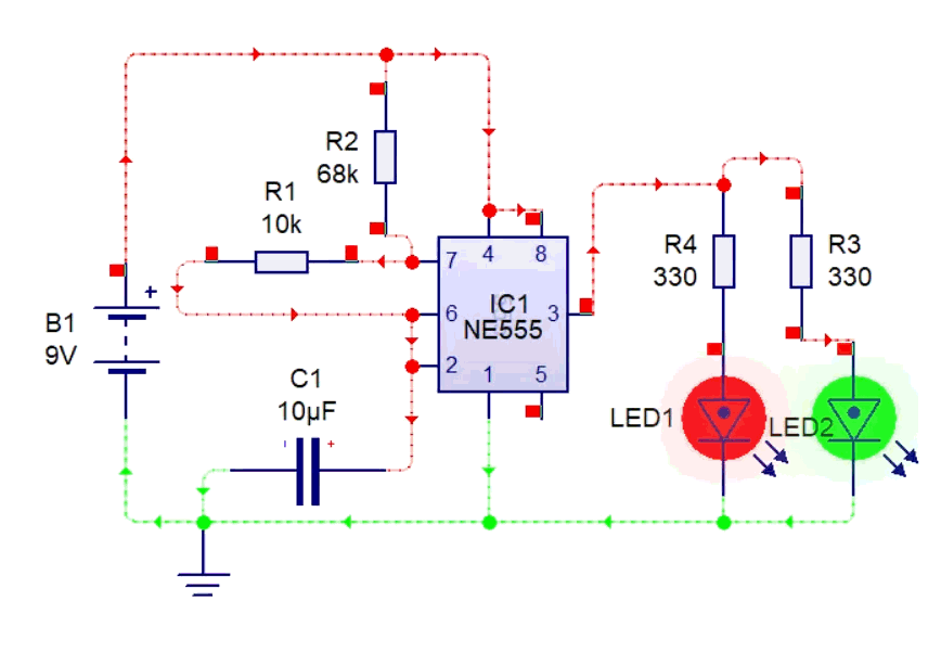
Frequency and Duty Cycle Calculation
Oscillation frequency for 555 LED blinker is calculated by: $ f=\frac{1.44}{(R_1+2R_2) \times C_1} $
Plugging in the values we get: $ f=\frac{1.44}{(10\ k\Omega+2 \times68\ k\Omega) \times10\mu F} \approx0.986\ Hz $
That is approximately 1 flash per second.
Following is a Table of NE555N Astable Component Selection for Common Frequencies
| Frequency | R1 Value | R2 Value | C1 Value | Application Example |
|---|---|---|---|---|
| 1 Hz | 10 kΩ | 68 kΩ | 10 μF | Slow indicator blinking |
| 5 Hz | 10 kΩ | 13 kΩ | 10 μF | Medium pace blinking |
| 10 Hz | 1 kΩ | 10 kΩ | 10 μF | Fast blinking |
| 100 Hz | 1 kΩ | 4.7 kΩ | 0.1 μF | Visual effects |
| 1 kHz | 1 kΩ | 4.7 kΩ | 0.01 μF | Audio tone generation |
Precise One-Shot (Monostable)
This is how the action goes in 555 timer as monostable multivibrator. When triggered by external signal, the monostable configuration of 555 timer produces a single output pulse of precise duration. This configuration suits applications that require accurate timing intervals, switch debouncing, and event sequencing.
Unlike the astable mode application, the monostable circuit has only one stable state (output LOW) unless triggered again, after which it produces a single pulse and returns to its stable state.
In the 555 timer as a monostable multivibrator, the mechanism of producing a single precise duration pulse begins when a pulse of <1/3 $ V_{cc} $ is applied to the trigger pin (pin 2). This signal triggers the internal flip-flop, causing the output to go HIGH and disconnecting the discharge transistor (Pin 7). This causes the capacitor to begin charging through the timing resistor. Once the capacitor voltage reaches 2/3 $ V_{cc} $, the threshold comparator resets the flip-flop, causing the output to return to LOW, and the discharge transistor rapidly discharges the capacitor. The output pulse width is determined solely by the values of the timing resistor and capacitor, following the formula: $ T\ =\ 1.1\ \times\ R\ \times\ C $
Parts List for Circuit Of NE555N Timer as Monostable Multivibrator
Following parts are required to make the circuit for 555 timer as monostable multivibrator:
| Part Name | Value | Quantity |
|---|---|---|
| NE555N IC | – | 1 |
| Resistor | 10 kΩ, 470 kΩ, 470 Ω | 1, 1, 1 |
| Capacitor | 10μF, 0.1μF | 1,1 |
| Push Button | – | 1 |
| LED | – | 1 |
| Power Supply | 5V – 12V DC Source | 1 |
Circuit Diagram of NE555N Timer as Monostable Multivibrator


Pulse Width Calculation
Using the following formula, we calculate the pulse width duration for 555 timer as monostable multivibrator:
$ T\ =\ 1.1\ \times\ R\ \times\ C $; $ T=\ 1.1\ \times\ 470,000\ \times\ 0.00001 $ ; $ \ \ T=\ 5.17\ s $
NE555N Timer Monostable Debounce Strategy
Mechanical switches often show contact bouncing that is multiple make/break contacts when pressed. The monostable 555 circuit efficiently debounces the switch because:
- It responds only to the first trigger signal that falls below 1/3 $ V_{cc} $
- The circuit ignores following bounces during the output pulse period
- The output pulse remains clean and consistent duration regardless of input bouncing
Bistable 555 Timer Mode – Latching Switch
Bistable 555 timer mode is the 3rd core functional mode of the NE555N timer IC. In bistable 555 timer mode, the IC functions as a basic digital logic circuit—a Set-Reset (SR) flip-flop. It has two stable states: output HIGH and output LOW.
In this mode, the output remains in either state until an external trigger changes it. This externally triggered mode makes it perfect for toggle circuits or simple memory units that retain which button you pressed last.The circuit bypasses the internal timing components by directly controlling the internal flip-flop with the Trigger and Reset inputs.
Parts List for Circuit Of 555 Timer as Bistable Multivibrator
To operate the NE555N timer IC in bistable mode, following parts are needed:
| Part Name | Value | Quantity |
|---|---|---|
| NE555N IC | – | 1 |
| Resistor | 10 kΩ, 330 Ω | 2, 1 |
| Capacitor | 0.1μF | 1,1 |
| Push Button Switches | – | 2 |
| LED | – | 1 |
| Power Supply | 5V – 12V DC Source | 1 |
Circuit Diagram of 555 Timer as Bistable Multivibrator


Frequency & Duty Cycle
In 555 Timer as Bistable Multivibratormode, the frequency is not applicable. The output is not oscillating; it is a stable DC voltage level (either HIGH or LOW). Similarly, Duty Cycle is also not applicable. The concept of duty cycle does not apply to stable DC output.
NE555N Timer vs Other 555 Variants
Because of its simplicity, adaptability, and wide range of applications, NE555N timer IC has garnered significant attention of manufacturers. Due to this attention, many different variants with additional features were introduced. Below is a comparison table of NE55N vs the other variants for quick selection guide:
| Variant | Process | $ V_{cc} $ | Quiescent | Drive ability | Notes |
|---|---|---|---|---|---|
| NE555/LM555 | Bipolar | 4.5–16 V | ~2 mA typ | Strong | Classic, robust. |
| TLC555/LMC555 | CMOS | 2–15 V (vendor) | Very low | Lower | Battery-friendly; better 50% options. |
| 556 | Dual 555 | As above | As above | As above | Two timers in one package. |
| 558 | Quad (gated) | As above | As above | As above | Different pinout/behavior; read datasheet. |
Conclusion
NE555 timer provides reliable and simple methods to create timers, and oscillators without the need of complex circuits or microcontroller ICs. Using resistors, and capacitors in required configuration, you can dial in almost any time interval from microseconds to minutes to hours in some cases. The timing signals produced using NE555 timer IC can be utilized in a wide range of applications. These include controlling servo positions down to notch, blinking LEDs, making an alarm and generating tone. NE555 timer IC has simple pinouts, and vast array of resources are available for its math calculation. We have provided two calculators above that do just that. Whether you’re a student, a hobbyist, or a seasoned engineer, little timer IC can go a long way in analog design thanks to its clever yet elegant circuitry within. Happy tinkering!
Glossary
| Term | Explanation |
|---|---|
| Trigger | Pin 2 on the NE555 timer IC serves as the dedicated input pin that detects when the voltage drops below a specific threshold (1/3 of $ V_{cc} $). |
| Control Voltage | The control voltage enables altering comparator reference levels. Applying an external voltage here allows precise tuning of pulse width or frequency. |
| Threshold | Pin 6 on monitors the voltage across the timing capacitor. When this voltage exceeds 2/3 $ V_{cc} $, the the output switches state. |
| Astable Mode: | NE555 timer IC configuration where the circuit continuously oscillates between high and low output states, with no stable state. |
| Bistable Mode | A Bistable mode refers is a configuration with two stable output states. In bistable mode, the NE555 timer operates as a flip-flop or latch, changing state on receiving a set or reset signal. |
| RC time constant | The RC time constant (τ = R × C) is how long it takes a capacitor in an RC circuit to charge or discharge to about 63% of the supply voltage. |
| Discharge transistor | It is an internal NPN transistor. The Pin 7 discharges the external timing capacitor to ground. This action is essential for generating accurate time intervals in both monostable and Astable modes. |
| $ V_{cc} $ | The positive supply voltage pin (pin 8) on the NE555 timer IC, typically 4.5V–15V, powers the internal circuitry. All timer reference voltages and output states are set relative to $ V_{cc} $. |
| Monostable Mode | In monostable mode, the NE555 timer has one stable state and one temporary state. When triggered, it outputs a single pulse for a set duration, then returns to its stable state until triggered again. |
| Duty Cycle: | Duty cycle is the percentage of a cycle during which the output stays high. |
FAQs
What’s the difference between NE555 and NE555N?
The term NE555 is the name of the family of chips; whereas the NE555N is a specific is through-hole DIP package variant with the same core specifications.
What capacitor type should I use for timing?
For accurate timing using the NE555N timer, use ceramic capacitors or polyester film capacitors. These capacitors have low drift and leakage. X7R capacitors are also acceptable for non-precision use; electrolytics enable long delays but increase error due to tolerance and leakage.
Which flip-flops do the NE555N Timer use internally?
Internally, the 555 timer IC uses a bistable flip-flop to preserve its output state based on input. This flip-flop ensures stable state transitions and memory of output until it is reset.
What is the threshold in a NE555N Timer and how does it affect operation?
The threshold pin monitors when the voltage surpasses 2/3 $ V_{cc} $. Once this level is exceeded, the timer resets the internal flip-flop, flipping the output state. As a result, the threshold determines the timing intervals that govern the 555 timer’s operation.
What is the maximum frequency of NE555 vs CMOS variants?
The standard NE555 timer IC can operate at ~ 500 kHz. In contrast, CMOS versions can reach the MHz range because of their faster switching speeds and lower internal capacitance.
What are the practical disadvantages/limitations of using a 555 today?
The disadvantages of NE555 timer IC include:
- Higher power consumption
- Limited frequency range
- Limited integration options
How can I check if my 555 timer is working?
To test a 555 timer quickly, configure it in Astable mode with visible LED output blinking or measure output on oscilloscope to confirm the pulse generation.
What is the NE555N used for—what I can build with a 555?
NE555N is widely used for oscillators, timers, pulse generators, PWM controls, and time delay circuits in DIY and industrial applications.
How do I make a simple clock with a 555?
To create a straightforward clock generator, configure the 555 timer in Astable mode. By selecting appropriate resistor and capacitor values, you can set the output frequency to create a square wave, which is used as a clock signal.
Why does my NE555N Timer stops at low voltages?
A typical NE555N IC needs more than or equal to 4.5 V to function. Below this voltage, the comparators and output stage within the IC cannot reliably switch, and the reset pin margin to halt the timer IC shrinks. If you want to use 2–3 V, use CMOS 555 (e.g., TLC555) and ensure to keep the load current low
Is a NE555N Timer digital or analog?
The NE555N timer IC functions as an analog device. This is because it relies on continuous voltage for timing functions. It operates by comparing voltages and switching output states accordingly.
What is the control-voltage (pin 5) for, and when should I use it?
The control voltage (pin 5) allows external adjustment of the internal voltage divider reference. It is used to enable modulation of threshold and trigger levels for frequency tuning.
Is the 555 timer powered by AC or DC? (practical guidance)
The 555 timer is powered by DC voltage, typically between 4.5V to 15V.
How accurate is a 555 timer, and what affects accuracy?
The accuracy of the NE555N timer IC depends on RC component tolerances, temperature variations, and supply voltage stability. Common deviations can begin from 1%.
What is the maximum delay achievable with a 555 monostable?
The maximum achievable delay in the NE555N timer IC’s monostable mode is several minutes. The achievable delay is limited by capacitor leakage and resistor values; the practical upper range is ~100 seconds.
How much power/current does NE555N timer vs CMOS consume?
The NE555N timer utilizes ~10mA -15 mA during operation. The CMOS variants utilize a few microamps, which are suitable for low-power applications.
How do I trigger a 555 timer reliably?
To reliably trigger the NE555 timer, clean the signal with a resistor + capacitor (also called Schmitt trigger), so that 555 timer gets one clean pulse. Keep RESET pin tied to $ V_{cc} $ (high) so it doesn’t reset by accident.
Can a 555 timer drive a relay, DC motor, or servo directly—and when should I add a driver?
The NE555N timer IC can directly drive small relays or LEDs. However, when controlling higher current loads like DC motors or servos, it is recommended to utilize a transistor or MOSFET driver circuit.