Introduction
If you’re looking to build a high-performance DIY audio amplifier for your home setup or even as an amp for car audio, this guide walks you through a practical and educational project based on the popular TDA2050 chip.
We’ll be building a bridged audio amplifier capable of powering a single speaker with greater output using two amplifier chips working together which is perfect for experimenting with sound quality, bass response, and gain handling.
This setup is ideal not only for home audio projects but also for those exploring audio amplifier automotive systems, where compact power delivery and thermal stability are essential.
This step-by-step build offers a hands-on way to understand the fundamentals of audio amplification.
What Is a Bridged Audio Amplifier?
In a bridged amplifier, two amplifier ICs drive opposite ends of a speaker. One chip amplifies the signal, while the other inverts it doubling the voltage swing across the load.
This setup significantly increases power output, which is especially useful for subwoofers or passive midrange drivers in car or home systems.
In our case, the TDA2050 bridged configuration can deliver up to 35–50W RMS into an 8-ohm speaker, depending on the power supply and cooling.
This project is perfect for enthusiasts interested in home or car audio systems, including amp audio amplifier setups and learning how amplification works from the ground up.
Audio Amplifier Circuit Diagram
Refer to the following schematic for the bridged TDA2050 audio amplifier:

Component Checklist
Below is a list of essential parts. Many of these are available at Fly-Wing Technology, which supplies high-quality components ideal for this build.
Core Components
- TDA2050 audio amplifier: ICs (2 units) – Main audio amp ICs (Class AB)
- 22µF Electrolytic Capacitors (2 units)
- 1000µF Electrolytic Capacitors (2 units)
- 470nF Film Capacitors (2 units)
- 680Ω Resistors (2 units)
- 22kΩ Resistors (2 units)
- 7Ω Resistors (2 units)
- 8Ω Speaker (1 unit)
Additional Materials
- Dual ±18V power supply (±15V also works for lower output)
- Breadboard or prototyping board
- Heatsinks and thermal paste
- Audio input cable (3.5mm or RCA)
- Soldering tools and multimeter
- Safety glasses (for final power-up)
Step-by-Step Build Instructions for Audio Amplifier
Step 1: Prepare a Dual-Rail Power Supply
The bridged TDA2050 amplifier requires a ±18V dual rail power supply, which means you need three output terminals from your power source: +18V, 0V (ground), and -18V. Each TDA2050 IC acts as an individual audio amp amplifier stage, combining to deliver higher output across the speaker load in bridged mode
This configuration allows the amplifier to handle AC audio signals symmetrically and produce higher output swing.
You can use a dual-rail bench power supply or create one using a center-tapped transformer and linear regulators.
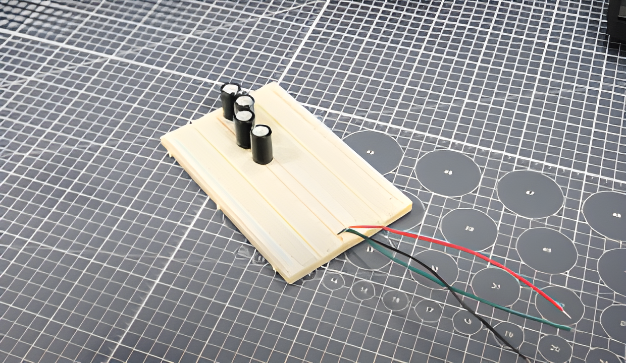
Add high-value electrolytic capacitors (e.g., 1000µF or more) across each supply rail (+18V to ground and -18V to ground). These capacitors stabilize voltage under load and reduce transient drops during bass-heavy playback.
Step 2: Assemble the Breadboard Layout Using TDA2050 audio amplifier
Place two TDA2050 audio amplifier ICs with enough spacing to accommodate wiring and heatsinks.
Since it’s a bridged configuration, one chip will act as the non-inverted channel and the other as the inverted counterpart.
Together, they will drive both ends of the speaker, effectively doubling the output voltage swing across the load.
Quick Overview of Pins (TDA2050):
- Pin 1: Non-Inverting Input
- Pin 2: Inverting Input
- Pin 3: V–
- Pin 4: Output
- Pin 5: V+
Wire both ICs according to the schematic. Ensure proper decoupling near the ICs with 100nF ceramic capacitors to reduce high-frequency noise.
Step 3: Connect Feedback and Bootstrap Components
Each amplifier stage uses a feedback loop to control gain and maintain linearity:
- Connect a 22kΩ resistor between the amplifier output and inverting input (Pin 4 to Pin 2).
- Add a 680Ω resistor in series with a 22µF capacitor from the inverting input (Pin 2) to ground. This sets the low-frequency cutoff point and gain stability.
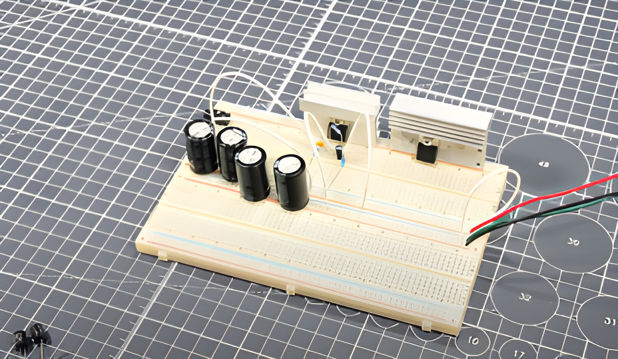
Step 4: Install Rail Capacitors for Stability
Since many basic bench power supplies don’t have sufficient built-in filtering for transient audio loads, adding large electrolytic capacitors (1000µF to 2200µF) between the power rails and ground can greatly improve performance under load.
This helps absorb sudden current surges from bass notes or peaks in music playback.
Place the capacitors close to the power pins of each TDA2050 IC.
Step 5: Attach Heat Sinks and Cooling Fan
The TDA2050 is a Class AB amplifier, which typically operates with 50–70% efficiency. As a result, significant power is lost as heat.
Mount small aluminum heatsinks on each TDA2050. Use thermal paste between the chip and heatsink to improve heat transfer. Use a small cooling fan to provide additional airflow.
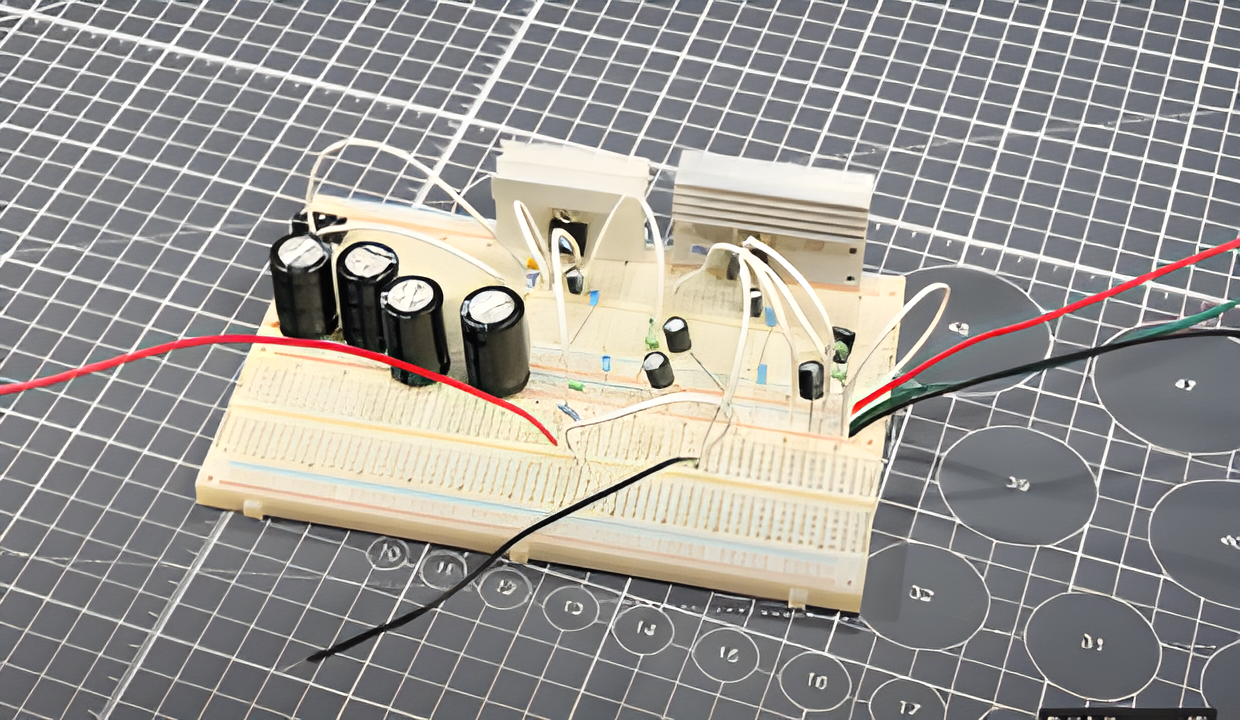
Step 6: Wire Up the Audio Amplifier Input and Speaker Output
Connect your audio input source (like a phone, laptop, or MP3 player) through a 10kΩ resistor to the non-inverting input (Pin 1) of the first TDA2050 audio amplifier.
Ground the source and connect to the amplifier’s input ground. Optionally, place a 1µF coupling capacitor in series to block DC offset from the input.
For speaker output, wire the positive terminal to the output of one TDA2050 (Pin 4), and the negative terminal to the output of the second TDA2050 audio amplifier.
Since this is a bridged amp, do not connect any speaker terminal to ground. Ensure your speaker is rated at 8Ω or higher to avoid overloading the chips.
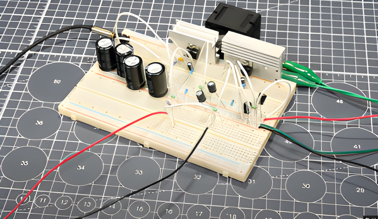
Step 7: Test the Circuit at Low Volume
Power on the circuit with the supply set to ±18V and a current limit of around 2A. Connect the input signal and slowly raise the source volume. If you hear weak or distorted sound, recheck:
- The orientation of your feedback and bootstrap components
- IC pinout alignment
- Proper soldering and wire continuity
If all is well, you should hear a clean and strong audio output.
Step 8: Check Speaker Load and Impedance
Before testing with other speakers, always measure the DC resistance of the speaker with a multimeter.
The bridged configuration of the TDA2050 should not be used with speakers below 8Ω. Using 4Ω or 6Ω speakers can cause overheating, distortion, or even blow the ICs at high volume.
If needed, wire two 4Ω speakers in series to safely create an 8Ω load.
Step 9: Stress Testing at Normal Volume
Once your circuit is working, play test tones or bass-heavy music at moderate volume. Monitor the temperature of the ICs.
If they heat up excessively, shut down the supply and improve cooling or reduce input gain. Optionally, use a clamp meter on the speaker wires to roughly estimate the output current.
For example:
- 30Hz test tone → ~2A
- 20Hz test tone → ~3A
Don’t push the amp beyond its rated thermal limits. Using a fan or larger heatsinks significantly extends safe operation time.
Step 10: Finalize Prototyping and Continue Experimentation
With stable performance confirmed, you can experiment with:
- Adding volume control using a potentiometer at the input
- Swapping in better coupling capacitors for improved fidelity
- Exploring other audio sources like Bluetooth modules
Even without a PCB, the breadboard version is capable of decent power and sound quality. Just be sure to always load the amp with the correct impedance and never touch exposed wires while powered.
Fina Thoughts
You’ve now built a fully functional audio amplifier that’s low-cost, battery-safe, and compact..
Creating your own audio amplifier from scratch gives you firsthand experience with audio electronics, heat management, and circuit safety.
Whether you’re experimenting with a custom amplifier in car audio setup or building your first DIY sound system, projects like these are the gateway to deeper electronics knowledge.
To speed up your build, consider using pre-tested modules and components from Fly-Wing Technology.