The RS232 Communication Protocol was first introduced in 1960 to enable serial data transmission between two devices. Engineers initially designed it to establish a connection between Data Terminal Equipment (DTE), such as a computer, and Data Communication Equipment (DCE), such as a modem, ensuring proper and reliable communication. This protocol defines the electrical characteristics, signal timing, and connector specifications, making it easier to understand how data is transmitted between devices at the hardware level..
Although newer communication standards like Wi-Fi, USB, and Ethernet have emerged, the importance of RS232 remains significant. It can transmit data over longer distances compared to TTL or I²C protocols and offers better noise immunity, ensuring clearer signal transmission.
Today, RS232 continues to play a vital role in the electronics and industrial sectors, commonly used as a connection interface between modems, controllers, and other communication devices.
This guide aims to help students and engineers of all levels understand and master this fundamental protocol — from grasping its basic principles to applying it in complex, real-world communication systems.
What is Serial Communication?
- Devices widely use serial communication to transmit data between a transmitter and a receiver. Through this method, systems can send data in various forms, such as text, audio, video, or digital signals. It works by transmitting information in binary form, where a high logic level represents ‘1’ and a low logic level represents ‘0’.
- In everyday life, serial communication is all around us — from mobile phones and personal computers to industrial machines — all rely on this method to exchange data efficiently.
- Its importance is particularly evident in embedded systems, where it enables reliable communication between components using interfaces such as SPI (Serial Peripheral Interface), I²C (Inter-Integrated Circuit), and most notably, RS232, which remains a foundational standard for serial data transmission.

Serial Communication: Different Modes
Serial Communication Important Factors
What is Baud Rate?
The speed at which data is transmitted in a serial communication system is defined by the baud rate.
The measurement is given in bits per second (bps), and the number of signal changes or symbols transmitted each second is represented by it.
A higher baud rate means faster data transmission. For example, when the baud rate is 9600 bps, 9600 bits of data are transmitted every second. The rate at which information is sent and received between devices is determined by this value, providing a clear indication of the efficiency and speed of communication..
Framing
Framing refers to the structure of data being transmitted from the sender to the receiver. It defines how many bits make up one complete unit of data (called a data frame). Typically, a frame consists of 8 data bits, along with start, stop, and control bits.
The start bit signals the beginning of data transmission, while the stop bit marks its end. Control bits, such as parity bits, help ensure that the data is received correctly. This structure allows the receiver to identify, process, and interpret the incoming data accurately.
Synchronization Process
Synchronization ensures that both the transmitting and receiving devices operate in coordination. It keeps the data transmission timing aligned so that the receiver reads each bit at the correct moment.
In synchronous communication, proper timing is maintained by sharing a clock signal between devices. In asynchronous communication, synchronization is achieved through the use of start and stop bits, which enable the receiver to recognize when data transmission begins and ends. This process ensures smooth and reliable data exchange.
Error Control System
The error control system detects and corrects any mistakes that occur during data transmission. Common techniques include parity bits, cyclic redundancy check (CRC), and checksums.
-
Parity bits check for errors by maintaining even or odd counts of binary 1s.
-
CRC and checksums verify the integrity of transmitted data by comparing calculated values on both ends.
These methods ensure that the transmitted data remains accurate, consistent, and free from corruption, maintaining high communication reliability.
What is RS232?
- RS232 is a serial communication protocol that transmits data between two devices, typically connecting Data Terminal Equipment (DTE), such as a computer, and Data Communication Equipment (DCE), like a modem.
- This protocol defines the standard for serial data exchange and commonly appears as part of computer communication ports. The RS232 interface usually employs a 25-pin (DB25) or 9-pin (DB9) connector, both featuring a D-shaped design that ensures secure and correct connections. The DB25 connector, sometimes referred to as a C module, is an extended form of RS232D with 22 pinouts, while the DB9 connector is more compact and widely used due to its smaller, efficient design.
- The Telecommunications Industry Association (TIA) named the RS232 standard TIA-232, after its Recommendation 232. It supports both synchronous and asynchronous transmission modes, making it versatile for various communication needs.
- RS232 operates using two signal levels, representing binary logic — logic 1 (marking state) and logic 0 (spacing state). It enables reliable two-way communication between devices using its DTE and DCE configuration.
- The protocol supports multiple baud rates, such as 2400 bps, 4800 bps, and 9600 bps, and allows devices to transmit data at different speeds depending on the application. RS232 can transmit data over a distance of up to 20 meters with a typical data rate of 1.492 kbps.
- Due to its noise immunity, simplicity, and robust performance, engineers continue to use RS232 in laboratories, industrial equipment, and various embedded systems where dependable serial communication is needed.

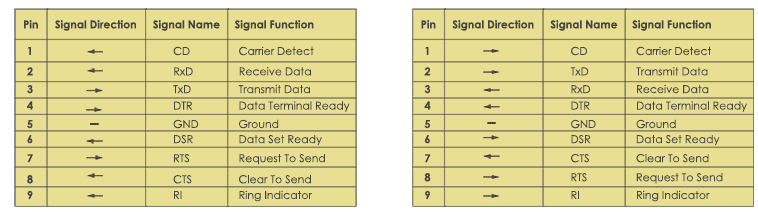
RS232 Pin Configuration
The RS232 standard defines a set of pins that enable proper communication between devices by transmitting and receiving signals.
For most computers and microcontrollers, engineers commonly use the DB9 connector (9-pin D-sub connector) as the standard interface for serial communication. Below is the description of each pin and its function:
Pin 1 – DCD (Data Carrier Detect)
- Direction: Input to DTE
This pin indicates whether a modem has detected a carrier signal from a remote device. In practical use, such as in internet connections, the DCD signal remains high when a stable connection is established.
Pin 2 – RXD (Receive Data
- Direction: Input to DTE
- This pin receives serial data from the DCE and delivers it to the DTE. It collects data bits in sequence. For example, on a PC, the RXD pin receives data from a microcontroller connected via the TXD line.
Pinout 3 – TXD (Transmit Data)
- Direction: Output from DTE
- This pin transmits serial data from the DTE to the DCE. It is primarily responsible for sending control commands — for instance, when a PC sends a command to a connected controller, the TXD pin transmits these instructions in bytes.
Pin 4 – DTR (Data Terminal Ready)
- Direction: Output from DTE
- This pin shows that the computer is powered on and ready to communicate. It sends a signal to the DCE to indicate that the DTE is prepared for data transmission.
Pin 5 – GND (Signal Ground)
- Direction: Reference Point
- This pin provides a common electrical ground between connected devices. It ensures voltage stability and prevents potential differences that could damage the equipment, enabling stable and error-free communication.
Pins 6 – DSR (Data Set Ready)
- Direction: Input to DTE
- This pin signals that the DCE powers on and is ready for data communication. It coordinates with DTR to establish a proper connection. For instance, when a modem is turned on, the DSR signal goes high to indicate readiness.
Pin 7 – RTS (Request to Send)
- Direction: Output from DTE
- This pin is used to send a signal from the DTE to the DCE, requesting permission to transmit data. It plays a vital role in hardware handshaking and data flow control during synchronous transmission. For example, before sending data, the RTS signal goes active to indicate “I’m ready to send.”
Pin 8 – CTS (Clear to Send)
- Direction: Input to DTE
- This pin responds the DCE, indicating that it is ready to receive data. It works in conjunction with RTS to manage data flow. When a modem is ready, the CTS line goes high, signaling the terminal to begin transmission.
Pins 9 – RI (Ring Indicator)
- Direction: Input to DTE
- This pin signals an incoming call on a phone line. When a call is detected, the RI signal goes high to alert the terminal device.
RS232 Electrical Specifications
The RS232 protocol uses distinct voltage levels to transmit data and control signals. These voltage levels ensure reliable communication between devices by clearly distinguishing between logic high and logic low states.
Signal Voltage
| Logic State | Voltage Range | Details |
| Logic ‘1’ (Marking State) | +3V to +25V |
high state
|
| Logic ‘0’ (Spacing State) | −3V to −25V |
low state
|
| Indeterminate State | −3V and +3V |
Undefined;
|
Using these voltage levels, RS232 ensures reliable data transmission over longer distances.
Control Voltage
RS232 uses negative logic, inverting the logic levels compared to the standard data signal.
| Logic State | Voltage Range | Details |
| Logic ‘1’ | −3V to −25V |
high state
|
| Logic ‘0’ | +3V to +25V |
low state
|
The control voltage regulates data flow and ensures smooth communication between interface devices. If the voltage value falls within the range of −3V to +3V, the signal becomes difficult to identify due to weak or noisy transmission.
Slew Rate
The slew rate defines how quickly a signal changes from a high level to a low level, measured in volts per microsecond (V/µs). The maximum slew rate for the RS232 protocol is 30 V/µs. This characteristic helps minimize crosstalk and interference between adjacent signal lines, ensuring clearer communication.
Line Impedance value
The line impedance refers to the resistance between the DTE and DCE devices that affects signal flow. Typically, its value ranges from 3 to 7 ohms. Maintaining this resistance level helps reduce signal distortion and allows stable and efficient data transmission.
RS232 Serial Cables types
There are two cables used in the RS232 protocol for performing serial communication:
-
Null Modem
-
Straight-Through
Null Modem
This type of RS232 cable is used to connect two DTE modules without the help of any intermediate devices.
A null modem cable connects the TX pin of one connector to the RX pin of the second connector, and the RX pin of the first connector to the TX pin of the second connector.
A null modem cable, also called a crossover cable, is named so because it uses crossed wiring.

Straight-Through
A straight-through RS232 cable connects a DTE device with a DCE module. In this cable, the DTE’s TX pin connects to the DCE’s RX pin, and the RX pin connects to the other device’s TX pin. This connection is straight, not crossed..
RS232 communication working
As we know, the RS232 protocol is a serial communication standard, meaning it transmits data in a single direction through a single data line.
For two-way communication, RS232 uses three wires along with a combination of control signals. The protocol follows an asynchronous communication method, which means it does not require a clock signal to synchronize the transmitter and receiver.
Instead, start and stop bits are used to help the receiver identify the beginning and end of each data frame. During transmission, a small time delay may occur between bits, representing the inactive state of the signal for logic 1 and logic 0.
During operation, the transmitter sends the start bit first to indicate the beginning of data transmission. The start bit represents logic 0. The transmitter then sends five to nine data bits, depending on the configuration.
If a parity bit is included, the transmitter sends a total of 8 bits; if no parity bit is used, it sends 9 data bits instead.
After sending the complete data, the transmitter sends the stop bits.These stop bits may consist of 1, 2, or 1.5 bit times, marking the end of the transmission.
What is Handshaking in the RS232 Protocol
In the handshaking process, the transmitter (sending point) and the receiver (receiving point) establish communication settings to ensure accurate data transfer.
The process depends on the speed of both the sender and receiver and helps coordinate when they can send or receive data without errors. In asynchronous data transmission, the system does not require a special handshaking protocol, while in synchronous communication, devices often use handshaking signals for coordination.
No Handshaking in RS232
In RS232 communication, if the system does not use handshaking, the receiver temporarily holds data sent from the transmitter before the transmitter sends new data. The receiver stores incoming data in a buffer memory until it can process it.
This buffer holds one unit of data at a time, so the receiver must process the first data before new data arrives.
If the receiver cannot process data quickly enough, this can lead to data loss.
To avoid such issues, accurate buffer management is essential in the no-handshaking mode of the RS232 protocol.
RS232 vs UART.
| Feature | RS232 | UART |
| Full Form | Recommended Standard 232 |
Universal Asynchronous Receiver Transmitter
|
| Definition | A physical layer standard that defines voltage levels, signal timing, and connectors for serial communication |
A hardware module used for serial data transmission between devices.
|
| Function Level | Works at the hardware interface level |
Works at the data link level
|
| Voltage Levels | ±3V to ±15V |
0V (LOW) and 3.3V/5V (HIGH) for logic levels (TTL standard).
|
| Signal Type | inverted signaling |
non-inverted signaling
|
| Medium/Interface | DB9 or DB25 connectors for transmission. |
connected internally on a microcontroller board.
|
| Communication Distance | used for 15 meters reliably. |
limited to short distances (a few centimeters) on the same PCB.
|
| Data Format | Defines start, stop, and parity bits for data transmission over long distances. |
Handles framing internally; user configures baud rate, stop bits, and parity.
|
| Communication Type | Point-to-point | It also uses point-to-point communication, but you can extend it using converters (RS-485). |
| Physical Layer | Specifies electrical characteristics and cable wiring. |
Does not define the physical layer, only the logic for data transfer.
|
| Speed | 115.2 kbps. |
1 Mbps or more,
|
| Error Checking | Parity bit and hardware handshaking (RTS/CTS). |
Parity bit and software error handling.
|
| Flow Control | Hardware-based using RTS/CTS lines. |
Software-based or optional hardware control.
|
| Uses | External communication between a PC, modem, or an industrial device. |
Internal communication between the microcontroller and the peripheral
|
| Voltage Compatibility | uses a level converter (e.g., MAX232) to connect with TTL devices. |
Directly compatible with TTL logic levels.
|
| Example Connection | PC, Modem, or PLC |
Microcontroller, GPS/Bluetooth Module
|
RS232 Interfacing with Microcontrollers
The MAX232 IC is used for interfacing microcontrollers with RS232 devices. It acts as a buffer between the controller and the RS232 port, converting TTL logic levels to RS232 standard levels (+10V and –10V). Some microcontrollers communicate with PCs through built-in serial ports using this IC.
MAX232 IC introduction
The MAX232 includes two transmitters and two receivers, allowing connection of two serial ports on a single board.
-
The transmitters convert TTL signals from the controller into RS232 levels.
-
The receivers convert RS232 signals from the PC into TTL levels used by the controller.
To maintain stable voltage levels, connect five 1 µF capacitors to the IC.
MAX232 Pin Configuration
-
The MAX232 has 16 pins divided into transmitter and receiver sections.
-
Transmitter pins receive TTL signals from the controller and output RS232 signals to the PC.
-
Receiver pins receive RS232 signals from the PC and output TTL signals to the controller.
-
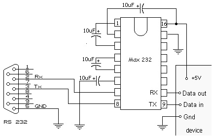
Why are capacitors in MAX232?
Capacitors in the MAX232 support the internal voltage generator.
-
One capacitor works as a voltage doubler, converting 5V to +10V.
-
Another works as a voltage inverter, generating –10V.
-
The remaining three capacitors act as bypass capacitors for the Vcc, V+, and V– pins.
Conclusion
RS232 is a dependable and commonly used serial communication protocol in the electronics industry. It was first introduced in 1962 by EIA, after that, it became easy to use low-cost techniques for data exchange in computers and other devices.
Its important features, like voltage level, pins, and handshaking techniques, ensure stable and error-free communication over moderate distances. Different communication protocols are employed in industries, but RS232 is still preferred in different industries like industrial automation, embedded systems, medical devices, and control applications, where reliability and compatibility are preferred over speed. Its longevity features help to get accurate design and a universally accepted communication protocol.

Frequently Asked Questions About RS232
1. Is RS232 still used in circuits?
Yes, people still commonly use RS232 in industrial equipment, CNC machines, medical devices, barcode scanners, and smart building control systems.
2. What is the signal range of RS232 communication?
The RS232 signal range is from +3V to +15V for logic 0 and 3V to -15V for logic 1, measured with respect to ground.
Typically, voltages between +5V and +15V represent logic 0 (mark), while voltages between 5V and –15V represent logic 1 (space).
3. What are the basic differences between DB9 and DB25 connectors?
The main difference between DB9 and DB25 connectors is the number of pins:
-
DB9 has 9 pins, while DB25 has 25 pins.
Because of its smaller size and sufficient functionality for most RS232 communication, people use DB9 more commonly today instead of the larger DB25, which designers created for more complex circuits and higher data transmission needs.
4. Can you connect RS232 to a USB port circuit?
Yes, you can use an RS232-to-USB converter to connect RS232-compatible devices to USB ports.. This converter translates RS232 signals into USB-compatible signals, allowing communication between older serial devices and modern computers.