
Programmable Logic Devices (PLDs) are revolutionizing power-up sequencing in electronic systems. By integrating multiple discrete components into a single chip, PLDs simplify designs, reduce costs, and enhance reliability. This article explores the role of PLDs in power-up sequencing, their advantages over traditional methods, and best practices for implementation.
What Is Power-Up Sequencing and Why Is It Crucial?
Power-up sequencing ensures that electronic components receive power in a specific order, preventing damage and ensuring proper functionality. Incorrect sequencing can lead to latch-up conditions, bus contention, or even permanent damage to sensitive components. For instance, microcontrollers, FPGAs, DSPs, ADCs, and other devices often operate from multiple voltage rails, requiring precise sequencing to avoid immediate or long-term damage.
How Do Programmable Logic Devices Facilitate Power-Up Sequencing?
PLDs, such as the TPLD1201 from Texas Instruments, offer configurable logic and timing blocks that can generate symmetric power-up and power-down signals. These devices replace multiple discrete components, streamlining the design process and reducing the overall footprint. The TPLD1201, for example, allows for feedback mechanisms to verify the sequence, enhancing reliability.
What Are the Advantages of Using PLDs in Power-Up Sequencing?
-
Integration: Combines multiple functions into a single chip, saving PCB space and reducing component count.
-
Flexibility: Easily reconfigurable to accommodate different sequencing requirements.
-
Reliability: Reduces the risk of human error associated with discrete component assembly.
-
Cost-Effective: Lower overall system costs due to reduced component and assembly needs.
Which Applications Benefit Most from PLD-Based Power-Up Sequencing?
Applications requiring multiple voltage rails, such as adaptive SoCs, benefit significantly from PLD-based sequencing. For example, AMD’s adaptive SoCs necessitate that the POR_B input be asserted low during the power-on sequence and remain low for a minimum duration after all required supplies have reached their final voltages.
How Can Engineers Implement PLD-Based Power-Up Sequencing?
Engineers can implement PLD-based sequencing by:
-
Selecting an Appropriate PLD: Choose a PLD with sufficient I/O pins and configurable logic blocks to meet sequencing requirements.
-
Designing the Sequence Logic: Utilize PLD development tools to design the power-up and power-down sequences.
-
Programming the PLD: Load the designed logic into the PLD using the manufacturer’s programming tools.
-
Testing and Validation: Thoroughly test the implemented sequence to ensure reliability under various operating conditions.
Buying Tips
When selecting PLDs for power-up sequencing:
-
Assess Requirements: Determine the number of voltage rails and sequencing complexity.
-
Evaluate Tools: Consider the availability and ease of use of development and programming tools.
-
Check Support: Ensure the manufacturer offers adequate technical support and documentation.
Fly-Wing Technology (HK) Co., Limited has been consistently dedicated to assisting customers in finding hard-to-find parts quickly and accurately, as well as acquiring new and original parts at competitive prices since 2012. Their website offers consistently competitive prices that are in line with or lower than those of other leading online distributors or superstores. With warehouses in Hong Kong, they can purchase electronic components from all over the world, offering powerful competitive prices. They acknowledge the difficulty of sourcing obsolete electronic components and strive to provide the best solutions for their customers.
Electronic Components Expert Views
“Integrating power-up sequencing into a PLD not only streamlines the design but also enhances system reliability by reducing the potential for human error and component mismatch.” — Senior Engineer, Texas Instruments
FAQ
Q: What is power-up sequencing?
A: Power-up sequencing is the controlled application of power to different components in a specific order to prevent damage and ensure proper operation.
Q: Why are PLDs used in power-up sequencing?
A: PLDs integrate multiple discrete components into a single chip, offering flexibility, reliability, and cost savings in power-up sequencing applications.
Q: Can PLDs handle complex sequencing requirements?
A: Yes, PLDs can be programmed to handle complex sequencing requirements, making them suitable for applications with multiple voltage rails and timing constraints.
Discover how single-chip programmable logic devices (PLDs) can replace multiple discrete components in power-up sequencing circuits, reducing costs and saving PCB space.
Many of today’s electronic products, whether simple or sophisticated, require systematic power-up sequences to enable functions in the correct order and timing. Incorrect sequencing can lead to anything from minor user inconvenience to catastrophic product failure.
Traditionally, power sequencing in electronics involves multiple discrete logic devices and passive components. However, single-chip programmable logic devices (PLDs) now integrate all necessary discrete components. This article will explore various power-rail sequences and timing using multiple inputs and outputs.
The Limitations of Using Discrete Solutions
Let’s start by examining Figure 1, which illustrates a power-sequencing example based on a single-battery input.
This example will demonstrate how PLDs can simplify your designs while offering greater flexibility compared to discrete logic solutions. If the battery voltage is acceptable, the device will follow the sequence according to the timing shown in the figure.
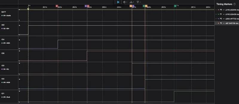
Figure 1. Power-sequencing example based on single-battery input. [click to enlarge]
Figure 2 is the circuit schematic for a discrete logic design that would generate the signals of Figure 1.
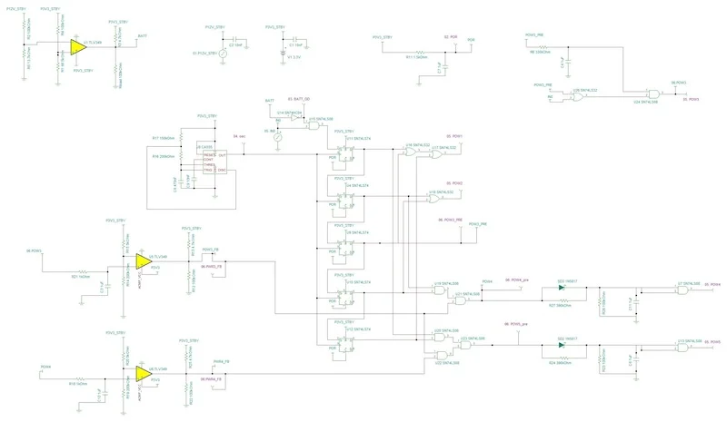
Figure 2. Analog and discrete logic power-sequencing schematic. [click to enlarge]
As you can see, supporting power sequencing through analog and discrete logic is straightforward. However, this approach is not optimal in terms of the number of devices and the required printed circuit board area.
Inevitably, the discrete approach will result in higher development and final product costs compared to a PLD-based design. Additionally, supporting analog and discrete logic requires you to negotiate, procure, store, and place numerous discrete devices and their associated passives on the PCB.
Simplify Power Sequencing With Programmable Logic
The Texas Instruments (TI) TPLD1202 PLD is a single-chip solution that can meet the requirements of our example power sequence. This PLD includes up to 40 different logic elements and is easily configurable to support a wide range of applications.
TI’s InterConnect Studio design tool provides a drag-and-drop interface to design, simulate, configure, and program TI PLDs without the need for coding. Figure 3 is a screenshot of InterConnect Studio and the power-sequencing circuit used to configure the TPLD1202 device.
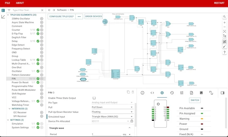
Figure 3. TPLD1202-based power sequencing through InterConnect Studio. [click to enlarge]
The circuit in Figure 3 uses an input-enable signal fed into a counter. The control data of the counter block, combined with the clock from the internal oscillator, sets the delay between each sequence signal. Since the counter reset triggers on the rising and falling edge of the enable signal, the device does not signal to begin power down until the input enable signal falls.
If we wanted to change the timing of the power-sequencing controller, a discrete resistor-capacitor network would require new RC values and a change to our bill of materials. With a PLD design, we could simply reconfigure the internal oscillator and associated dividers without needing to modify the bill of materials.
Powering Additional Voltages Up and Down
Since the example application relies on a battery for its power source, the voltage can vary based on the battery’s state. Building on the previous example, you can use additional logic functions to add another power-sequencing use case.
In Figure 4, the TPLD1202 checks for a specific voltage or voltage range on the POWER3 feedback before enabling POWER3. It then moves on to the POWER4 feedback to verify its requirements against the battery voltage (Figure 4). Only after meeting these voltage requirements will the product fully power up for operation.
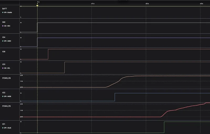
Figure 4. TPLD1202 power sequencing with voltage monitoring. [click to enlarge]
For power-down sequences, you can ensure safe power-down by using the same parameters monitored during power-up in reverse.
Tables 1 through 3 outline the savings achieved when using TI PLDs for power sequencing. As a starting reference, Table 1 identifies the 19 discrete components and their package sizes.
Table 1. Discrete logic bill of materials

As shown in Table 2, we can use a single PLD with a package size smaller than each of the 19 individual discrete components.
Table 2. Programmable logic bill of materials
 Finally, Table 3 shows the reductions in the bill-of-materials and the PCB area. A single TI PLD can translate into PCB space savings of over 99% and PCB cost savings of over $1 compared to discrete logic designs.
Table 3. PCB area comparison
 Further savings can be realized by eliminating the procurement costs associated with obtaining an additional 19 devices. For simplicity, we did not include passive components in our comparison, but you can also expect savings of up to 90% on the passives required for a TI PLD design.
Other PLD Use Cases
PLDs offer configurable logic with both digital and analog functions, popular interfaces, and integrated features such as oscillators that can optimize your design for:
- Functionality
- Bill of materials
- PCB area
- Procurement costs
- Manufacturing costs
PLDs also do not have the overhead associated with competing solutions such as field-programmable gate arrays. TI’s PLDs are simple to configure and program because you don’t need any experience with hardware description languages to use InterConnect Studio.
These PLD benefits also make them suitable for input/output expansion, sensor interfaces, LED control, and voltage monitoring.
