
Introduction
Modern portable electronic devices have become increasingly dependent on rechargeable lithium-ion (Li-ion) and lithium-polymer (Li-Po) batteries. From wearable electronics and wireless sensors to industrial handheld equipment and medical devices, battery-powered products are expected to operate longer, charge faster, and provide users with accurate information about the remaining battery capacity.
However, simply measuring the battery voltage is no longer sufficient for modern battery-powered applications. The battery voltage changes nonlinearly during charging and discharging, making it difficult to accurately estimate the remaining battery percentage using voltage alone. As batteries age, their characteristics also change. Therefore, reducing the accuracy of traditional voltage-based battery estimation methods. This is where a battery fuel gauge IC MAX17048, comes into play!
The MAX17048 is an ultra-low-power battery fuel gauge IC, which is used to estimate the State of Charge (SoC) of single-cell lithium-ion and lithium-polymer batteries. Due to its small footprint, low power consumption, and simple two-wire I2C interface, MAX17048 is widely used by design engineers for battery-powered embedded systems such as smart watches, smart glasses, and battery-powered earphones. It can be easily integrated with popular microcontrollers such as the ESP32, STM32, and Arduino using the I2C protocol. A simple block diagram of a battery-powered embedded system using a MAX17048 is shown below.
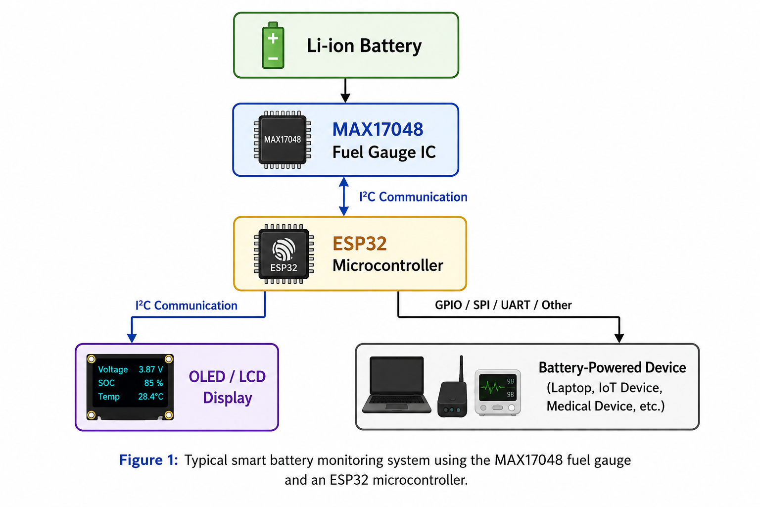
Whether you’re developing an IoT device, portable medical equipment, wearable electronics, GPS tracker, wireless sensor, or any battery-powered embedded system, this guide will provide the practical knowledge needed to successfully integrate the MAX17048 into your next hardware design.
What is the MAX17048?
The MAX17048 is an ultra-low-power battery fuel gauge integrated circuit (IC) developed by Analog Devices. It is designed to monitor the remaining capacity of a single-cell lithium-ion (Li-ion) or lithium-polymer (Li-Po) battery and provide an accurate estimate of the battery’s State of Charge (SOC). The MAX17048 is known for its miniature size footprint, minimum external components, and simple 2-wire I2C interface (SDA and SCL) to communicate with a host microcontroller like STM32 or ESP32.
This state estimation is highly demanded in consumer electronics and wearable electronic products such as IoT products, portable medical equipment, GPS trackers, and handheld consumer devices.
Understanding Smart Battery Monitoring Systems
A smart battery monitoring system is an electronic system designed to continuously monitor a battery’s condition and provide accurate information about its remaining capacity and operating status. Instead of relying solely on battery voltage, it uses a dedicated battery fuel gauge IC to analyze battery characteristics and estimate parameters such as the State of Charge (SOC).
This information is then communicated to a host microcontroller, allowing the system to display the remaining battery percentage, generate low-battery alerts, optimize power consumption, and improve the overall reliability of battery-powered devices.
Traditional Battery Monitoring vs. Smart Battery Monitoring
Many low-cost battery-powered devices estimate the remaining battery capacity by measuring battery voltage. Although this method is simple and inexpensive, it often produces inaccurate results because the discharge curve of a lithium-ion battery is not linear. Battery voltage is also influenced by temperature, load current, and battery aging.
| Feature | Traditional Voltage Monitoring | Smart Battery Monitoring |
|---|---|---|
| Battery Percentage Accuracy | Low | High |
| Voltage Measurement | ✔ | ✔ |
| State of Charge (SOC) Estimation | ✘ | ✔ |
| Low Battery Alerts | Limited | ✔ |
| Compensation for Battery Characteristics | ✘ | ✔ |
| Suitable for Modern Portable Devices | Limited | ✔ |
Table 1. Comparison between traditional voltage-based battery monitoring and smart battery monitoring using a fuel gauge IC such as the MAX17048.
Applications of Smart Battery Monitoring Systems
Smart battery monitoring systems are widely used in products that rely on rechargeable batteries and require accurate battery information. Common applications include:
🔋 Common Applications of Smart Battery Monitoring
Smart battery monitoring systems are widely used in products that rely on rechargeable batteries and require accurate battery information. Common applications include:
How MAX17048 Works
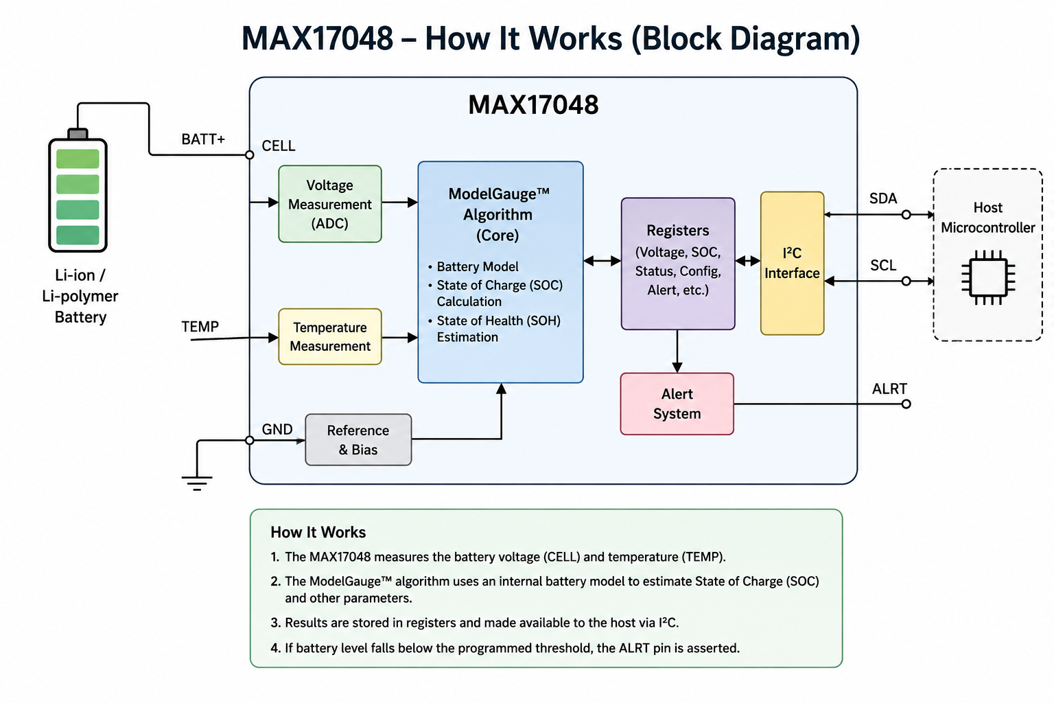
The MAX17048 battery SoC monitoring IC works on the fuel-gauge algorithm. Unlike traditional battery fuel gauges that rely on coulomb counting, the MAX17048 continuously monitors the battery voltage and applies an advanced mathematical battery model to determine the remaining battery capacity.
The heart of MAX17048 is the Model Gauge Algorithm, which compares real-time battery voltage with an internal battery model. By considering factors such as battery chemistry, discharge characteristics, and voltage response, the algorithm accurately estimates the battery’s State of Charge (SOC), even during varying load conditions.
State of Charge (SOC) Calculation
ModelGauge algorithm, the MAX17048 calculates the battery’s State of Charge (SOC). The SOC value represents the remaining battery capacity as a percentage, ranging from 0% (fully discharged) to 100% (fully charged). This information is stored in internal registers and can be read by a host microcontroller through the I²C interface.
Many wearable and smart devices, such as smartphones, smart watches, glasses, portable medical equipment, GPS trackers, and IoT devices, use this SOC value to display accurate battery level indicators.
Low Battery Alert Function
The MAX17048 includes an integrated low-battery alert feature that notifies the system when the battery reaches a predefined charge level. When the battery capacity falls below the programmed threshold, the ALRT pin is asserted, allowing the host microcontroller, such as an STM32 or an ESP32, to respond immediately.
MAX17048 Pinout and Functional Description
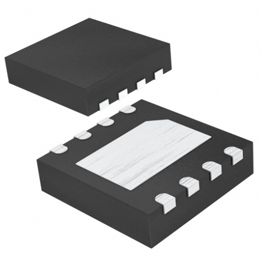
The MAX17048 is available in an 8-pin TDFN package and an 8-bump WLP package, making it suitable for compact battery-powered devices. Each pin performs a specific function related to battery voltage monitoring, power management, I²C communication, and system alerts. Understanding the pin functions is essential for designing a reliable battery fuel gauge circuit and ensuring accurate battery State of Charge (SOC) measurements.
MAX17048 Pin Configuration
| Pin | Name | Type | Functional Description |
|---|---|---|---|
| 1 | CTG | ⚫ Ground | Connect directly to GND during normal operation. Used internally by the MAX17048. |
| 2 | CELL | 🔵 Analog Input | Connect to the positive terminal of the single-cell Li-ion/Li-Po battery to accurately measure battery voltage. |
| 3 | VDD | 🟡 Power Input | Power supply input (2.5 V–4.5 V). Place a 0.1 µF bypass capacitor between VDD and GND. |
| 4 | GND | ⚫ Ground | Ground reference for the IC. Connect to the battery negative terminal and the system ground. |
| 5 | ALRT | 🟢 Digital Output | Open-drain, active-low alert output that signals low battery SOC or other programmed alert conditions to the host MCU. |
| 6 | QSTRT | 🟢 Digital Input | Quick-Start input used to restart the fuel gauge algorithm. Connect to GND if the feature is not required. |
| 7 | SCL | 🟢 Digital Input | I²C serial clock line used for communication with the host microcontroller. |
| 8 | SDA | 🟣 Bidirectional I/O | I²C serial data line used to read battery voltage, State of Charge (SOC), status, and configuration registers. |
Table 2. MAX17048 pin configuration and functional description.
Hardware Design Requirements
Designing a reliable battery monitoring circuit with the MAX17048 requires more than simply connecting the IC to a battery. However, Proper hardware design practices ensure accurate battery voltage measurement, stable I²C communication, low power consumption, and reliable operation under different environmental and electrical conditions.
Battery Requirements
The MAX17048 is specifically designed for single-cell Lithium-Ion (Li-ion) and Lithium-Polymer (Li-Po) rechargeable batteries.
Table 3. Recommended battery specifications for the MAX17048 fuel gauge IC.
Power Supply Requirements
The MAX17048 operates from a 2.5 V to 4.5 V supply voltage through the VDD pin. To ensure stable operation, use short PCB traces to minimize supply noise, place a 0.1 µF ceramic bypass capacitor between VDD and GND, and position the capacitor as close as possible to the IC.
I²C Interface Requirements
The MAX17048 communicates with the host microcontroller using the standard I²C interface. Therefore, connect the SDA and SCL pins of the MAX17048 to the microcontroller I2C pins. I2C data lines are open-drain inputs; therefore, use external pull-up resistors on both I²C lines (typically 4.7 kΩ or 10 kΩ, depending on bus speed and capacitance. Keep I²C traces as short as practical and avoid routing I²C signals close to noisy switching power circuits.
Recommended External Components
The MAX17048 requires only a few external components, making it ideal for compact battery-powered applications.
Table 4. Typical external components required for a MAX17048 battery monitoring circuit.
Typical Hardware Schematics Guideline for MAX17048
A well-designed hardware schematic is essential for achieving accurate battery monitoring and reliable communication with the MAX17048. Although the IC requires only a few external components, following the recommended reference design and PCB layout practices ensures stable operation and precise State of Charge (SOC) estimation.
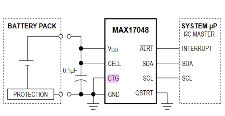
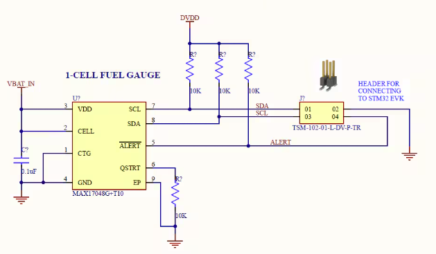
A typical MAX17048 hardware design consists of a single-cell Li-ion or Li-Po battery, the MAX17048 fuel gauge IC, a bypass capacitor of 0.1uF, I²C pull-up resistors, and a host microcontroller. The IC continuously measures the battery voltage through the CELL pin and reports battery information such as voltage, State of Charge (SOC), and alert status over the I²C interface.
Typical Hardware Schematic
A basic MAX17048 application circuit includes the following connections:
Table 5. Typical hardware connections for implementing the MAX17048 fuel gauge in a battery-powered embedded system.
Smart Watch Design: Real-World Design Example
To demonstrate how the MAX17048 battery fuel gauge is integrated into a commercial embedded system, this section presents a real-world smartwatch hardware design. Unlike simplified reference circuits, this design combines battery charging, protection, power management, wireless communication, sensing, memory, and display interfaces into a compact wearable PCB.
The smartwatch is powered by a single-cell Li-Po battery, which serves as the primary energy source for the entire system. The battery is monitored by the MAX17048 fuel gauge IC, allowing the microcontroller to accurately determine the battery’s State of Charge (SOC), display the remaining battery percentage to the user, and implement intelligent power management strategies. The system-level block diagram of the smartwatch design is shown below, and then each section along with its schematic design is explained.
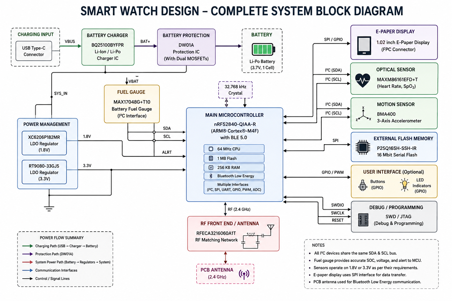
The following sections explain the purpose of each major hardware block used in the smartwatch design.
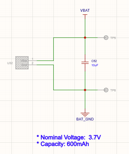
Li-Po Battery
The smartwatch uses a single-cell Lithium-Polymer (Li-Po) battery, which provides a lightweight, high-energy-density power source suitable for wearable electronics. The battery supplies power to all system components and is continuously monitored by the MAX17048 to provide accurate battery status information.
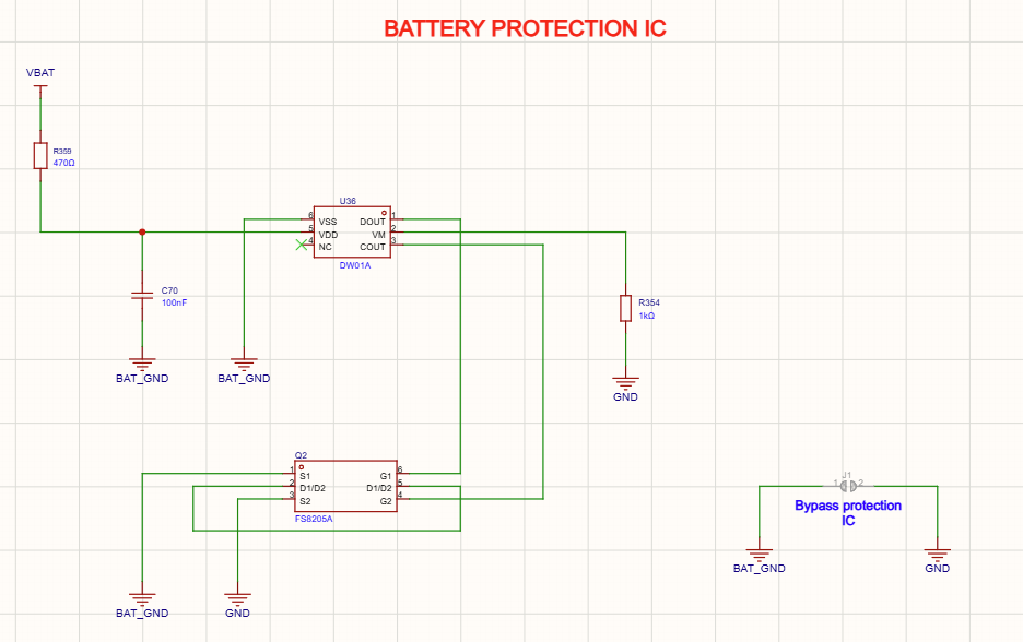
Battery Protection Circuit (DW01A)
The DW01A Battery Protection IC protects the Li-Po battery against abnormal operating conditions such as overcharging, over-discharging, overcurrent, and short circuits. Working together with the external MOSFET AO3400, it disconnects the battery whenever unsafe conditions are detected, significantly improving battery safety and extending battery lifespan.
USB Type-C Power Input
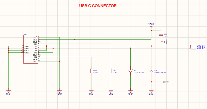
A USB Type-C connector is used in smartwatch design, which provides the external power source for charging the smartwatch battery. It allows users to recharge the device using standard USB chargers while also serving as the interface between the charging circuit and the external power supply.
Li-Ion Battery Charging Circuit (BQ25100)
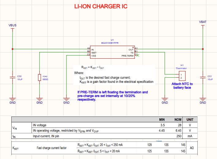
The BQ25100BYFPR is a highly integrated single-cell Li-Ion/Li-Po battery charging IC designed for compact portable devices. It manages the complete charging process, including pre-charge, constant-current charging, constant-voltage charging, and charge termination. Its integrated charging algorithm ensures safe, efficient, and reliable battery charging while minimizing the number of required external components.
Battery Fuel Gauge (MAX17048)
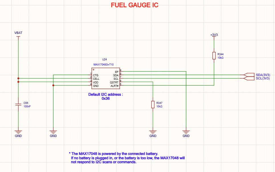
The MAX17048G+T10 continuously measures the battery voltage and estimates the remaining battery capacity using Maxim’s proprietary ModelGauge™ algorithm. Unlike conventional fuel gauges, it does not require a current-sense resistor, reducing PCB space and overall system cost.
The fuel gauge communicates with the main processor through the I²C interface, allowing the smartwatch to display an accurate battery percentage, estimate remaining operating time, and generate low-battery alerts when necessary.

Power Management and Voltage Regulation
The smartwatch uses dedicated voltage regulators to provide stable supply voltages for different subsystems.
XC6206P182MR for 1.8V Regulation
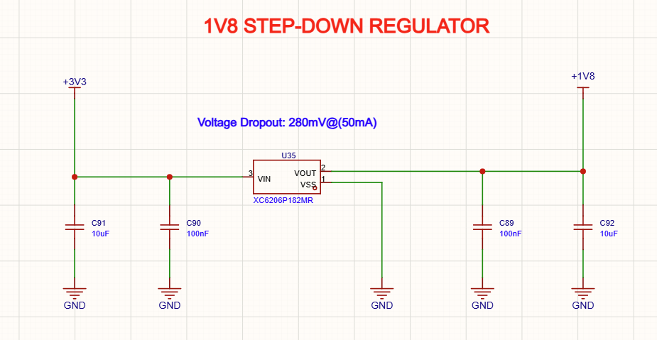
The XC6206P182MR is a low-dropout (LDO) voltage regulator that generates a stable low-voltage rail for sensitive low-power circuitry like MAXM86161 to monitor heart rate, pulse rate, and blood oxygen saturation (SpO₂). Its low quiescent current makes it well suited for battery-powered wearable devices.
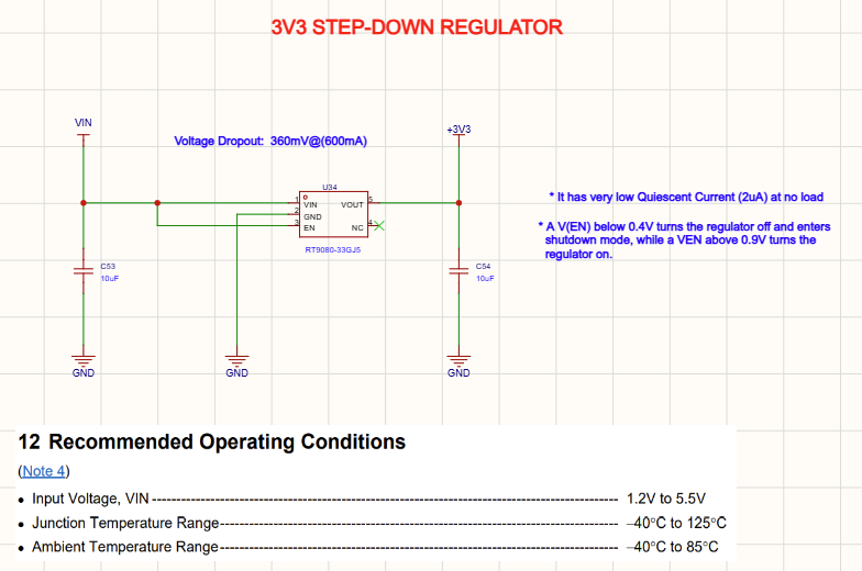
RT9080-33GJ5 for 3V3 Regulation
The RT9080-33GJ5 provides a regulated 3.3 V supply for digital components such as the microcontroller, external memory, sensors, and communication interfaces. Stable voltage regulation is essential for reliable operation and reduced system noise.
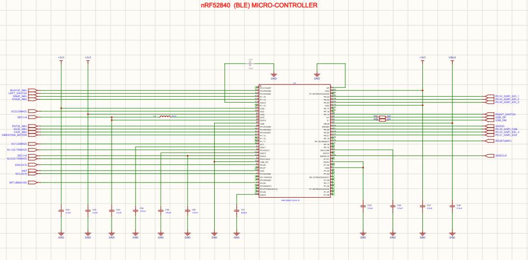
nRF52840 As the Main Microcontroller
The nRF52840-QIAA-R serves as the primary processing unit of the smartwatch. It integrates a powerful ARM Cortex-M4 processor with Bluetooth Low Energy (BLE) connectivity, enabling wireless communication with smartphones and other Bluetooth-enabled devices.
The microcontroller collects sensor data, controls the display, manages battery information received from the MAX17048, stores application data, and coordinates the overall operation of the smartwatch.
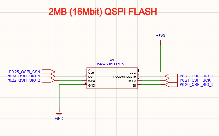
External Flash Memory using P25Q16SH-SSH-IR
The P25Q16SH-SSH-IR serial flash memory provides non-volatile storage for firmware, application data, fonts, graphical assets, configuration parameters, and firmware updates. Additional external memory allows more flexibility than relying solely on the microcontroller’s internal flash.
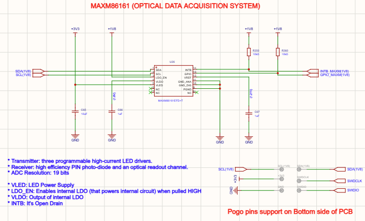
Optical Heart Rate and Pulse Oximeter Sensor
The MAXM86161EFD+T is an integrated optical biosensing module capable of measuring heart rate, pulse rate, and blood oxygen saturation (SpO₂). It combines LEDs, photodetectors, and analog front-end circuitry in a compact package, making it highly suitable for wearable health-monitoring applications.
The sensor communicates with the microcontroller using the I²C interface, allowing continuous health monitoring while maintaining low power consumption.
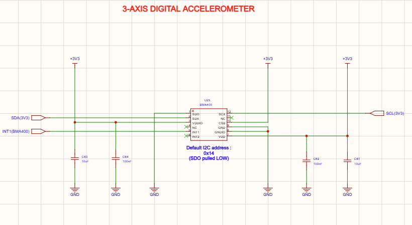
Motion Sensor (BMA400)
The BMA400 is an ultra-low-power three-axis accelerometer used to detect movement, orientation, step counting, activity recognition, and motion events. Its extremely low current consumption makes it ideal for always-on wearable devices that require long battery life.
Motion data collected from the BMA400 enables smartwatch features such as fitness tracking, gesture detection, sleep monitoring, and automatic display wake-up.
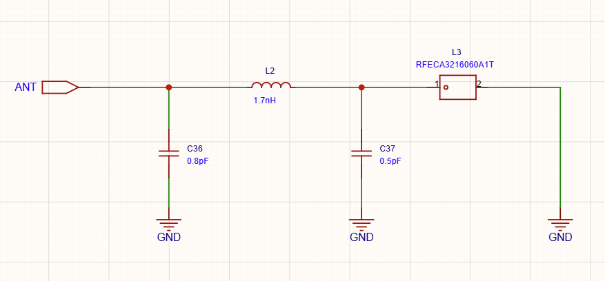
Bluetooth RF Matching Network and Antenna
The RFECA3216060A1T RF front-end component forms part of the Bluetooth antenna matching network. It optimizes impedance matching between the nRF52840 RF output and the antenna, helping maximize wireless communication range while reducing signal reflections and improving RF efficiency.
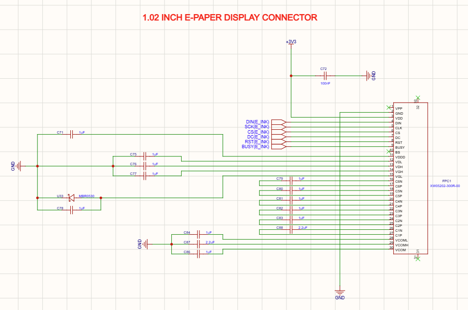
E-Paper Display Interface
The smartwatch uses a 1.02-inch E-Paper display, which connects to the PCB through a Flexible Printed Circuit (FPC) connector. E-paper displays consume extremely low power because they only require energy when updating the displayed image, making them ideal for battery-powered wearable products.
The microcontroller nRF52840 communicates with the display controller to update graphics, menus, icons, and battery status information.
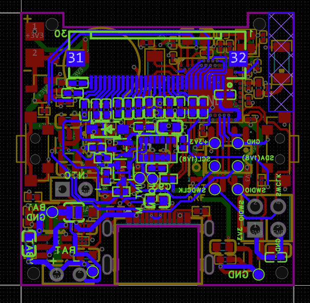
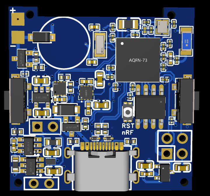
The PCB design layout and PCB 3D view of smart watch just discussed in this section shown below.
PCB Layout Guidelines for MAX17048
A well-designed PCB layout is essential for obtaining accurate battery voltage measurements and reliable communication when using the MAX17048 fuel gauge IC. Although the MAX17048 requires only a few external components, poor PCB layout can introduce electrical noise, voltage measurement errors, and communication issues that reduce the accuracy of the State of Charge (SOC) calculation.
Place the MAX17048 Close to the Battery Connector
The CELL pin measures the battery voltage directly, making it the most sensitive signal in the circuit. To minimize voltage drops and noise pickup, the MAX17048 should be placed as close as possible to the battery connector.
Place the Decoupling Capacitor Close to VDD
The 0.1 µF ceramic bypass capacitor should be placed immediately next to the VDD pin. A short connection between the capacitor, VDD, and GND minimizes supply noise and improves the stability of the internal analog circuitry.
Use a Solid Ground Plane
A continuous ground plane provides a low-impedance return path and helps reduce electrical noise throughout the circuit. Therefore, when using a MAX17048 for a wearable electronic and medical-related product, it is recommended to use a dedicated Ground plane.
Real-World Applications of MAX17048
The MAX17048 is a highly efficient battery fuel gauge IC used in a wide range of battery-powered electronic devices, from smartwatches and IoT sensors to portable medical equipment and consumer electronics. Designed specifically for single-cell Lithium-Ion (Li-ion) and Lithium-Polymer (Li-Po) batteries, it provides accurate battery voltage monitoring and reliable State of Charge (SOC) estimation while consuming very little power.
Its compact size, low-power operation, and easy I²C interface make it an ideal choice for modern portable and embedded systems where accurate battery management is essential. Some of the widely used applications where the MAX17048 are used are;
Real-World Applications of MAX17048
⌚ Smartwatches & WearablesUsed for accurate battery percentage monitoring in smartwatches, fitness bands, health trackers, and other wearable devices powered by single-cell Li-Po batteries. |
🌐 IoT DevicesProvides battery monitoring for wireless sensor nodes, smart agriculture systems, asset trackers, environmental monitoring devices, and remote IoT applications. |
🏥 Portable Medical DevicesIntegrated into portable ECG monitors, pulse oximeters, glucose meters, wearable health trackers, and patient monitoring systems where reliable battery information is critical. |
🎧 Consumer ElectronicsCommonly used in Bluetooth speakers, wireless headphones, handheld gaming devices, GPS receivers, barcode scanners, and many other portable consumer products. |
📡 Wireless Communication DevicesSupports intelligent battery management in Bluetooth Low Energy (BLE), Zigbee, Thread, Wi-Fi, and other battery-powered wireless communication modules. |
🏭 Industrial EquipmentUsed in portable industrial terminals, handheld testing instruments, maintenance tools, field data collection devices, and battery-powered industrial controllers. |
🏠 Smart Home ProductsIntegrated into smart locks, wireless alarm systems, smart doorbells, home automation sensors, and battery-powered security devices. |
💻 Embedded Systems & Development BoardsIdeal for embedded prototypes, evaluation boards, educational electronics projects, and custom battery-powered hardware requiring accurate fuel gauging. |
Conclusion
The MAX17048 is a compact and highly accurate battery fuel gauge IC designed for single-cell Li-ion and Li-Po battery-powered devices. Its algorithm eliminates the need for an external current-sense resistor while delivering reliable State of Charge (SOC) estimation, making it an ideal choice for portable and embedded systems.
In this guide, we covered the MAX17048’s working principle, pinout, hardware design requirements, reference schematic, PCB layout guidelines, and a real-world smartwatch design example. By following these design recommendations and best practices, engineers can develop reliable battery monitoring circuits that improve power management, extend battery life, and enhance the performance of modern battery-powered electronic devices.
Frequently Asked Questions (FAQ)
No. The MAX17048 is designed specifically for single-cell Li-ion and Li-Po batteries. It is not suitable for multi-cell battery packs or battery chemistries such as NiMH or lead-acid without additional circuitry.
The MAX17048 operates from a supply voltage of 2.5 V to 4.5 V, making it compatible with most single-cell battery-powered applications.
Incorrect battery readings are often caused by PCB layout issues, electrical noise on the CELL pin, poor grounding, inadequate power supply decoupling, or incorrect I²C communication.
The MAX17048 communicates using the standard I²C interface. Connect the SDA and SCL pins to the microcontroller’s I²C bus, add suitable pull-up resistors, connect the CELL pin to the battery positive terminal, and connect VDD and GND according to the recommended hardware schematic.
For most applications, 4.7 kΩ pull-up resistors are recommended for the SDA and SCL lines. Depending on the bus speed, supply voltage, and total bus capacitance, 10 kΩ pull-up resistors may also be suitable.
Yes. The MAX17048 is widely used in smartwatches, fitness trackers, and other wearable electronics because of its compact package, ultra-low power consumption, and accurate battery fuel gauging.


COMMENTS